physics - electricity
1/221
Earn XP
Description and Tags
Name | Mastery | Learn | Test | Matching | Spaced | Call with Kai |
|---|
No analytics yet
Send a link to your students to track their progress
222 Terms
what is electric current
the flow of electric charge round the circuit
current will ONLY flow…
around a complete (closed) circuit if there’s a potential difference
what is the unit for current
ampere, amps, A
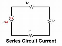
what will the current be like in a single, closed loop?
the current will have the same value everywhere in the circuit
what is potential difference (or voltage)
the driving force that pushes the charge round
what is resistance
anything in the circuit which slows the flow down
what is the unit for resistance
ohms, Ω
what does the current flowing through a component depend on
the potential difference across it and the resistance of the component
how does the resistance of a component affect the current
the greater the resistance across a component, the smaller the current that flows through it
what is the size of the current also known as
the rate of flow of charge
what is the equation to find the charge
Charge = Current x Time,
what is the symbol equation to find the charge
Q = It
what is the unit for charge
coulombs (C)
what is the unit for charge
amperes (A)
what is the unit for time
seconds (s)
when will more charge pass around the circuit
when a bigger current flows
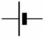
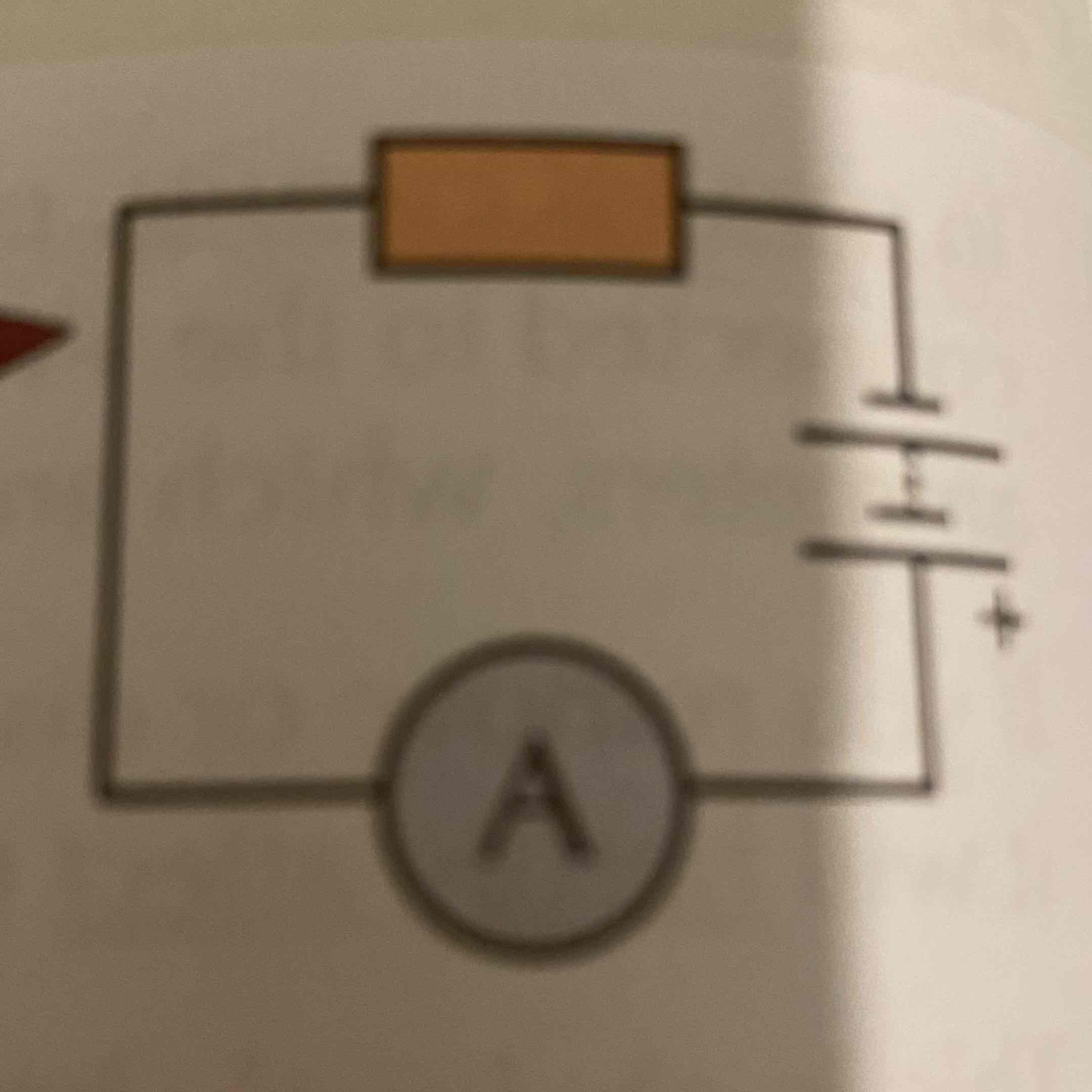
what is this
a cell
which line of the cell diagram is positive and negative
the long thin line is positive, the short thick one is negative
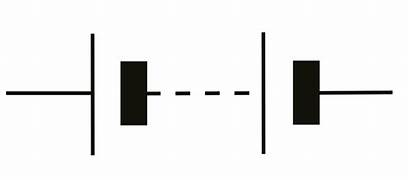
what is this
battery
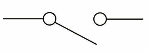
what is this
an open switch
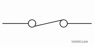
what is this
a closed switch
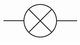
what is this
filament lamp/bulb
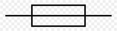
what is this
fuse
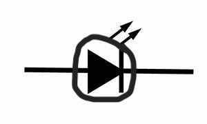
what is this
LED
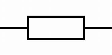
what is this
resistor
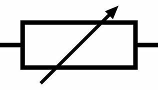
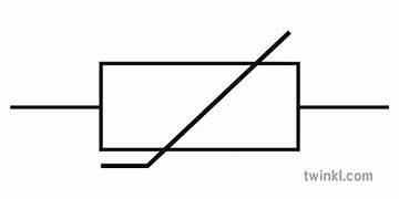
what is this
variable resistor
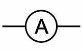
what is this
ammeter
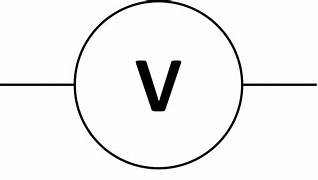
what is this
voltmeter
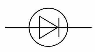
what is this
diode
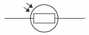
what is this
LDR - light dependent resistor
what is this
thermistor
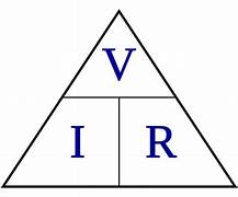
whats the formula to find potential difference
potential difference = current x resistance
whats the symbol equation to find potential difference
V = IR
whats the formula triangle for potential difference
whats the unit for potential difference
volts
whats the unit for current
amperes, amps, A
whats the unit for resistance
ohms, Ω
will the resistance of ohmic conductor change with current (e.g. wire/resistor)
no. at a constant temp, the current flowing through the ohmic conductor is directly proportional to the potential difference across it.
in the equation V=IR, which is constant
R (resistance)
which components will the resistance change for
filament lamps/bulbs or diodes
why does the resistance change in filament lamps/bulbs (2)
when an electrical charge flows through a filament lamp, some energy is transferred to the thermal energy store of the filament (getting hotter)
resistance increases with temperature, so when the current increases, the lamp heats up more and resistance increases
why does the resistance change in diodes (2)
resistance depends on direction of the current
will let current flow in one direction happily, but have a very high resistance if directions are reversed
what factors can affect the resistance of a circuit (2)
are components in series or parallel?
the length of wire used in the circuit
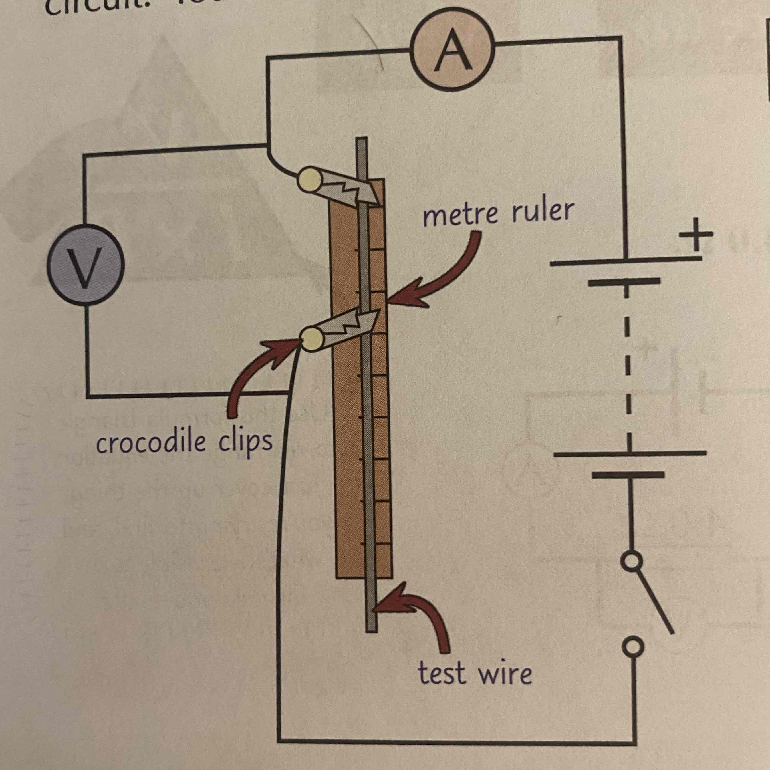
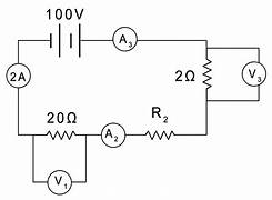
how to set up for practical: investigating effect of wire length on resistance
what is the ammeters role in this practical
measures the current (in amps) flowing through the test wire
whats important to remember when setting up the ammeter in an experiment
must always be placed in series with whatever you’re investigating
whats the role of the voltmeter in this practical
measures the potential difference across the test wire (in volts)
whats important to remember when setting up the voltmeter in an experiment
must always be placed in parallel around whatever you’re investigating (e.g. the ruler in this practical)
how to do the investigating resistance based on wire length practical (5)
attach a crocodile clip to the wire level with 0cm on the ruler
attach the 2nd crocodile clip to the wire (e.g. 10cm away from 1st clip). write down the length of wire between clips
close switch, then record current through the wire and the pd across it
open switch, move 2nd crocodile clip (e.g. another 10cm) along the wire. close switch again, record the new length, current and pd
repeat for different lengths
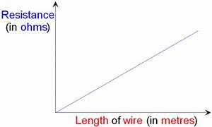
how to plot graph for this practical (3)
use measurements from practical to calculate resistance using R=V÷I
plot a graph against wire length and draw a line of best fit
your graph should be a straight line through the origin
what goes on the y axis of the graph
resistance
what goes on the x axis of the graph
length of wire
mistakes that could occur from this graph/experiment
graph doesn’t go through the origin (it could be because your 1st clip wasn’t attached exactly at 0cm so all your length readings could be off) this is called a systematic error.
hazards in this practical + 2 methods to prevent it
the wire could get hot, use a low pd to stop it getting too hot + turn off circuit between readings to allow it to cool off
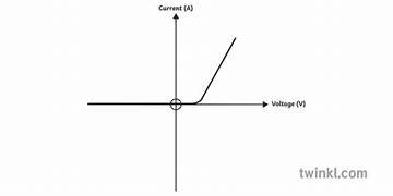
what is an I-V Characteristic
a graph that shows how the current (I) flowing through a component changes as the potential difference (V) across it increases
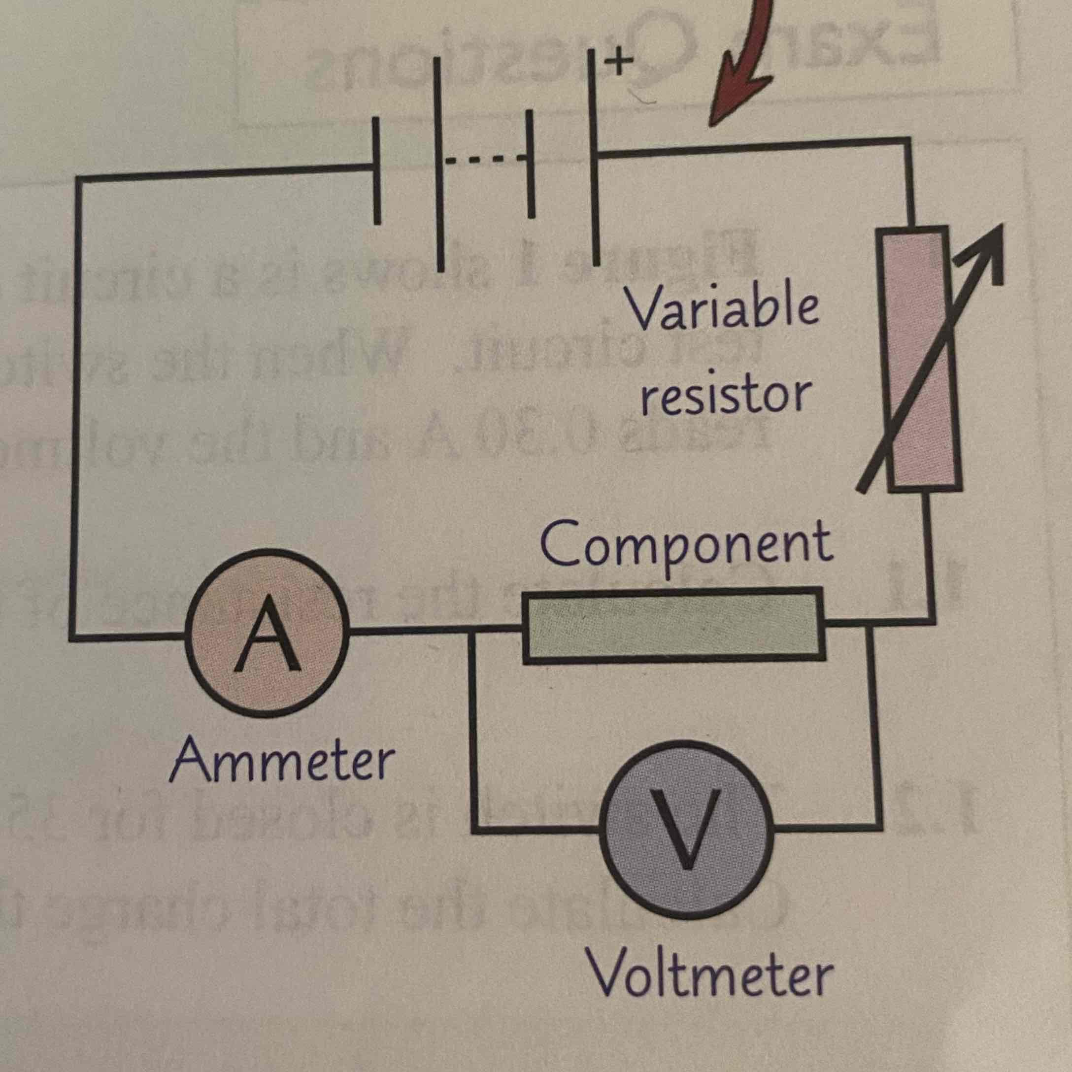
experiment to find a component’s I-V characteristic (5)
set up this test circuit
begin to vary the variable resistor- this alters the current flowing through the circuit and the pd across the component
take several pairs of readings from the ammeter + voltmeter to see how the pd across the component varies as the current changes.
repeat each reading twice more to get an average pd at each current
swap over the wires connected to the battery, so the direction of the current is reversed
plot a graph of current against voltage for the component
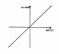
i-v characteristic for ohmic conductor (e.g. resistor at a constant temp)
current is directly proportional to pd
straight line
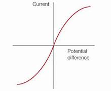
i-v characteristic for filament lamp/bulb
as current increases, temp increases, so resistance increases
less current can flow per unit pd as a result, so the graph gets shallower
i-v characteristic for diode
current only flows through a diode in 1 direction
diode has very high resistance in reverse direction
what is a LDR
a resistor dependent on the intensity of light
how will the resistance vary based on the brightness the LDR is in
in bright light → resistance falls
in darkness → resistance is highest
when are LDR’s useful in products- examples (3)
automatic night lights
outdoor lighting
burglar detectors
what is a thermistor
a resistor that is temperature dependent
how will the resistance vary based on the thermal conditions the thermistor is in
hot conditions → resistance drops
cool conditions → resistance increases
when are thermistors useful in products - examples (2)
car engine temperature sensors
electronic thermostats
what are sensing circuits used for
turning on or increasing the power to components depending on the conditions they’re in
what are sensing circuits used for
turning on or increasing the power to components depending on the conditions that they’re in
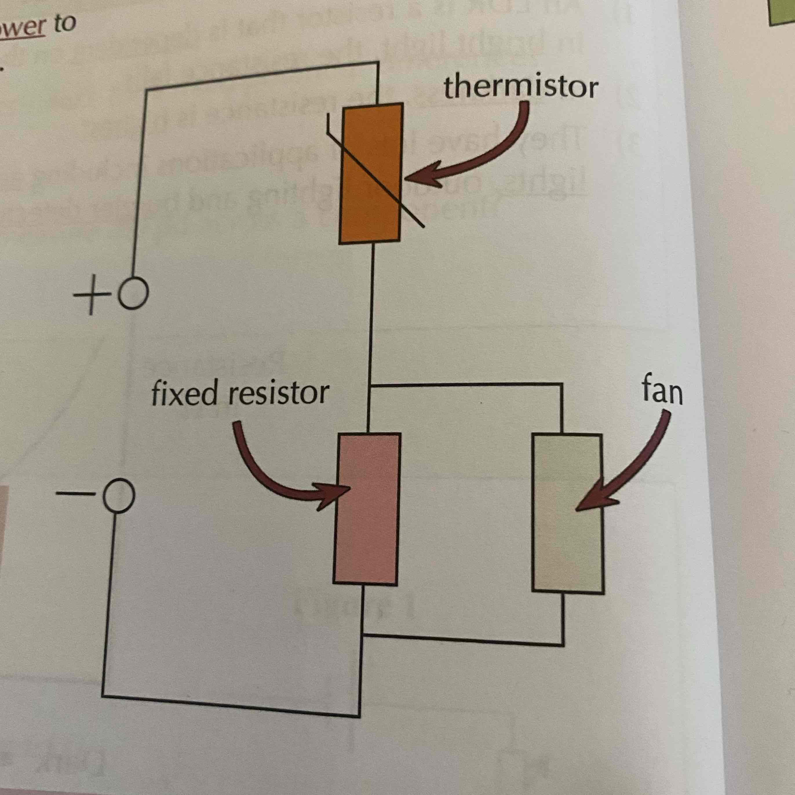
what is this sensing circuit going to control
a fan

what two components in the circuit will have the same potential difference and why
fixed resistor and fan because they’re connected in parallel
how is the potential difference of the power supply shared out between the thermistor and the loop (fixed resistor and fan)
according to resistances- the bigger a components resistance, the more potential difference it takes
what will happen to the circuit and fan as the room gets hotter
resistance of the thermistor decreases
takes a smaller share of p.d from the power supply
p.d. across the loop (fixed resistor + fan) rises
this makes the fan go faster
how else can you create a sensing circuit?
across a variable resistor instead of a fixed resistor
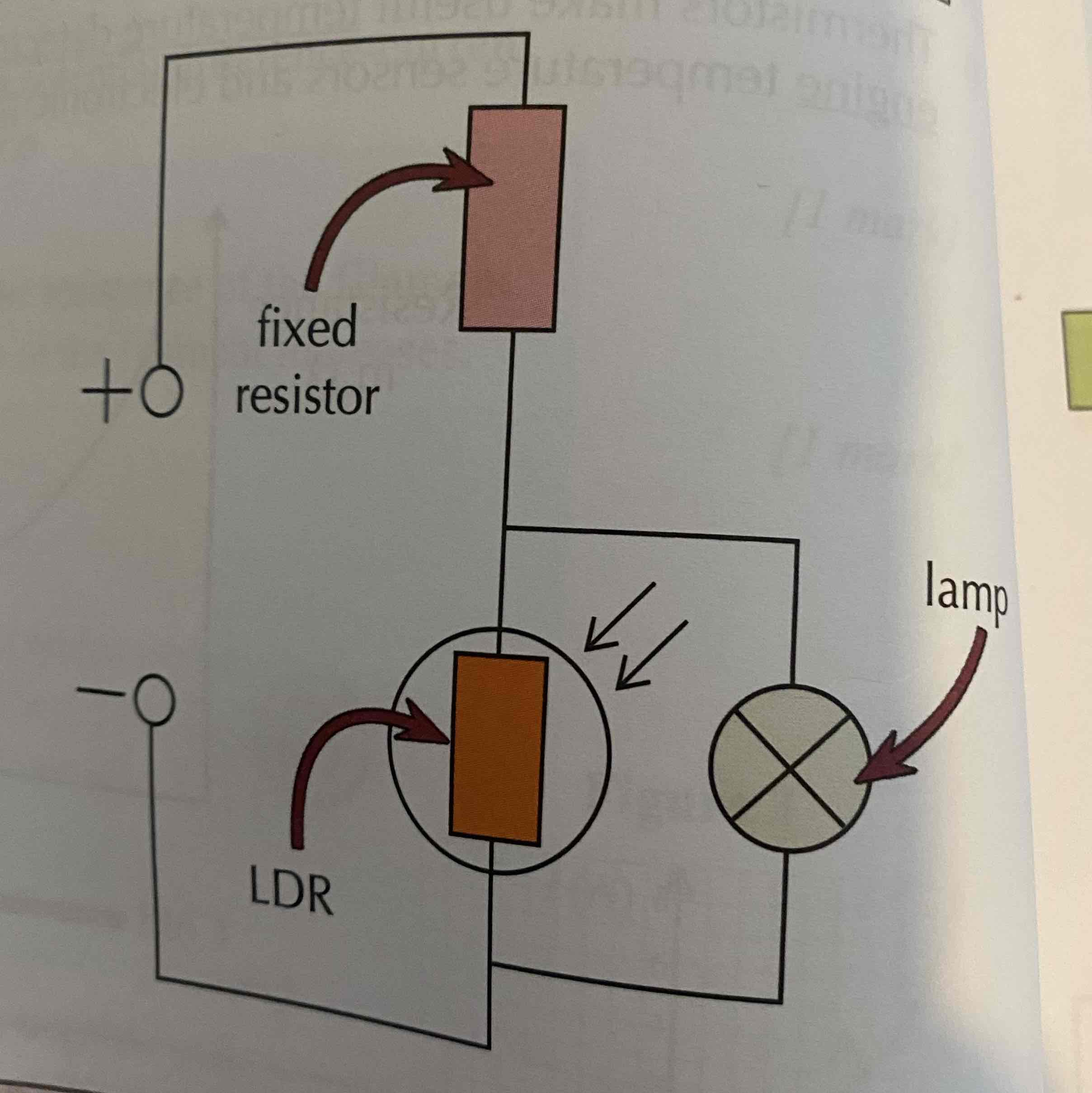
what is this circuit showing
a lamp
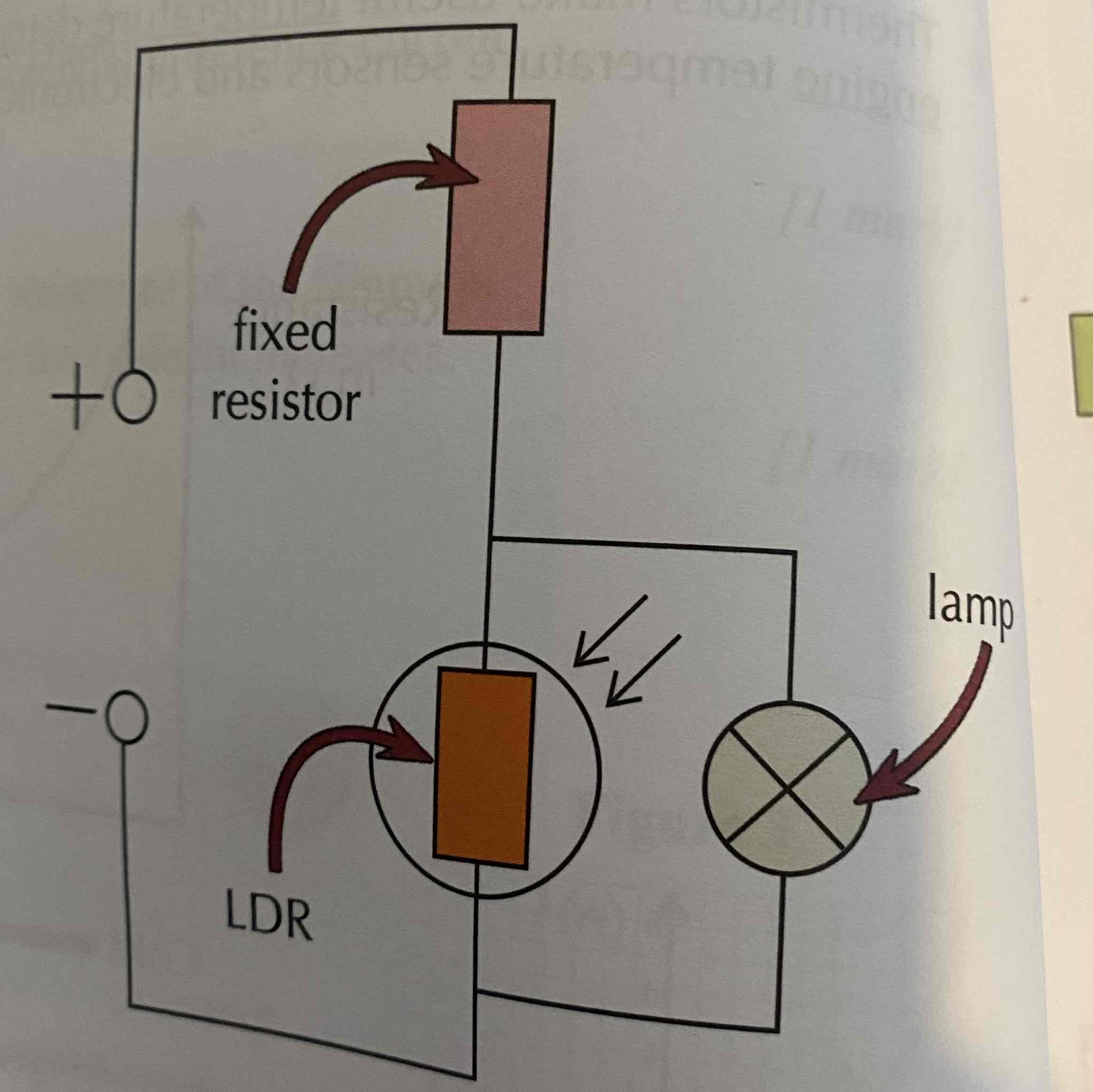
if you connect the bulb in parallel to an LDR…
the p.d. across the LDR and bulb will be high when it’s dark. the LDR’s resistance is high
how does p.d affect energy of a component
the greater the pd across a component, the more energy it gets
as the room got darker, the bulb..
would get brighter
how are series circuits formed
all components are connected in a line, end to end
what is the exception in series circuits
voltmeters, which will always be connected in parallel (they don’t count as part of your circuit)
what will happen if you remove or disconnect 1 component in a series circuit
the circuit is broken, and they all stop
are series circuits very handy
not really, they break easily, so very few things are connected in series
how do cell p.d.’s add up in a series circuit?
all the p.d’s add up e.g. 2 batteries of voltage 1.5V will supply a total of 3V
how will the total p.d. be shared?
it will be shared between the various components. you can see this through the equation: Vtotal = V1 + V2 + …
how is the current in series circuits
the current is the same everywhere (I1 = I2 = …)
how do you calculate the size of the current in series circuits
I = V ÷ R (current = p.d ÷ resistance)
how do you find resistance in series circuits
you find the sum of all the resistances (Rtotal = R1 + R2)
why is the resistance like this
because by adding a resistor in series, the resistors will have to share the total p.d.
how will the resistance be affected when a resistor is added
the total resistance of the circuit increases
the bigger a component’s resistance…
the bigger its share of the total p.d.
how are parallel circuits formed
each component is seperately connected to the power supply
what is the exception with parallel circuits
ammeters, which will always be connected in series
what will happen if you remove one component from a parallel circuit
it will hardly affect the other components
why are parallel circuits more useful then series circuits
they don’t break or stop working as easily as series circuits
in cars and household electrics why are parallel circuits useful
you have to be able to switch everything on and off separately
everyday circuits are…
a mixture of series and parallel circuits
how is the potential difference in parallel circuits
the same across all components. (V1 = V2 = V3 = …)
why is the p.d. the same in parallel circuits everywhere
all components get the full source pd, so the voltage is the same across all components. as a result, identical bulbs connected in parallel will all be at the same brightness
how is current in a parallel circuit
current is shared between branches. (Itotal = I1+I2+…)
how is resistance in a parallel circuit
adding a resistor will reduce the total resistance. (this is because the current has more than 1 direction to go in, so will increase the total current that flows around the circuit)
how to investigate the effect of adding resistors in series? (practical)
need 4 identical resistors
build the circuit using 1 resistor. (make note of the p.d. of the battery)
measure the current using the ammeter
(use to calculate resistance using R=V÷I)
add another resistor in series with the 1st resistor
measure the new current through the circuit (use this + pd of battery to calculate the overall resistance of the circuit)
repeat steps 4 + 5 till all resistors are added
plot a graph of the no. of resistors against total resistance of the circuit
what will the graph look like for this/as more resistors are added?
adding more resistors increases the total resistance
directly proportional, goes through origin