CHAPTER 5: MAXILLARY MAJOR CONNECTORS
1/50
There's no tags or description
Looks like no tags are added yet.
Name | Mastery | Learn | Test | Matching | Spaced |
|---|
No study sessions yet.
51 Terms
6 basic types of maxillary major connectors
single palatal bar
single palatal strap
palatal plate-type connector
u-shaped palatal connector
anterior-posterior palatal bars
combination A/P palatal strap–type connector
definite tooth support
must be provided whenever it is necessary for the palatal connector to make contact with the teeth for reasons of support
accomplished by establishing definite rest seats on the predetermined abutment teeth
located far enough above the gingival attachment
to provide for bridging of the gingival crevice with blockout
located low enough on the tooth
to avoid unfavorable leverage
located low enough on the mx incisors and canine
to avoid incisal interference of the opposing dentition
results when MC components resting on unprepared inclined tooth surfaces
slippage of the denture
orthodontic movement of the tooth
ways to prevent sequelae due to gingival third trauma
provide adequate gingival relief
one should support the major connector with definite rests on the teeth
locate the connector far enough away from the gingival margin
to avoid entrapment of food debris
to avoid any possible restriction of blood supply
sharp & angular form
should be avoided in any portion of a palatal connector
—all borders should be tapered toward the tissue
—all gingival crossings should be abrupt and at right angles to the major connector
single palatal strap
22-gauge matte plastic pattern suitable for rigidity
bulk can interfere with speech when placed anteriorly
should not be used with anterior replacements due to torque and leverage issues
can be rigid without bulk and tongue interference if cast framework material is distributed in three planes
suitable for short-span tooth-supported bilateral edentulous areas and tooth-supported unilateral edentulous situations
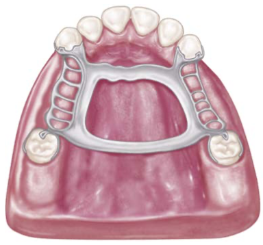
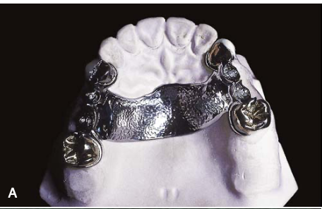
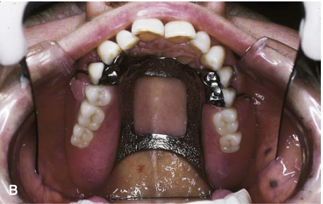
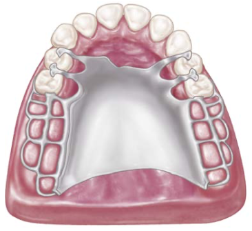
combination A/P palatal strap–type connector / CAPPS
symmetrically placed components are more likely to accept by the tongue
rigid palatal major connector suitable for almost any maxillary partial denture design
maxillary major connectors should cross the midline at a right angle; not on a diagonal
strength lies in longitudinal connectors on either side, forming a square or rectangular frame
posterior connectors should be flat and 8mm wide, located posteriorly to avoid tongue interference
8mm wide
measurement for anterior & posterior part of A/P palatal strap–type connector
[ 9mm for uniformity ]
7-9mm
measurement for each side part of A/P palatal strap–type connector
[ 8mm for uniformity ]
classes II and IV
what class does combination anterior-posterior connector design mostly used
class III
what class does single wide palatal strap mostly used
class I
what class does palatal plate–type or complete coverage connector mostly used
A/P palatal strap–type major connector
anterior component — flat strap located posteriorly to avoid rugae coverage and tongue interference
posterior component — strap is thin, 8mm wide, located posteriorly on hard palate
positioned at right angles to midline, not diagonally
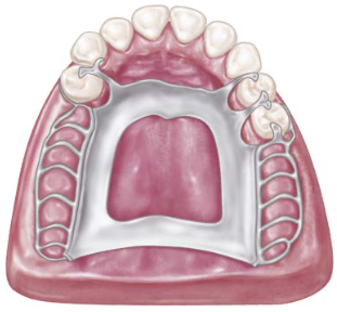
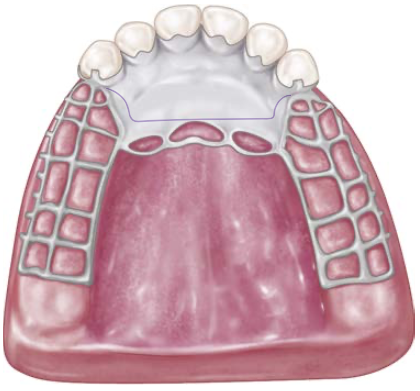
palatal plate–type connector
used for 7-8 remaining teeth
covers 2/3 or half of the hard palate
anterior border follows valleys between rugae
defined as thin, broad, contoured palatal coverage
posterior border located at hard and soft palates junction
in bilateral distal extension, indirect retainers are essential
anatomic replica palatal castings maintain uniform thickness and strength
provisions for a butt-type joint pass through the pterygomaxillary notch
palatal plate
the term used to designate any thin, broad, contoured palatal coverage
used as a maxillary major connector and covering one half or more of the hard palate
advantages of anatomic contours of the palate
corrugation adds strength for thinner casting
retention depends on denture base's retention
interfacial surface tension enhances prosthesis retention
allows creation of thin metal plate replicating patient's palate
surface irregularities require electrolytic polishing for uniform thickness
retention resistance is proportional to denture base contact area
forces that retention must be adequate to resist
forces of gravity
pull of sticky foods
violent forces of coughing and sneezing
action of moving border tissue against the denture
3 ways the palatal plate may be used
as a plate that covers two or more edentulous areas
as complete or partial cast plate extending posterior to hard and soft palates junction
provides anterior palatal connector with posterior acrylic resin denture base extension
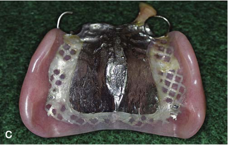
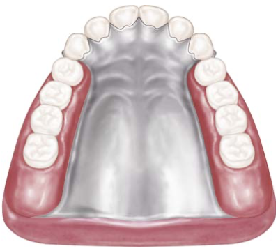
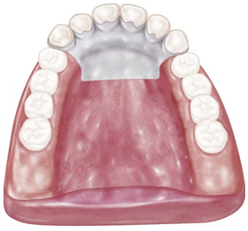
complete coverage palatal major connector
terminates at the junction of the hard and soft palates
alteration of natural palatal contours can affect speech
portion contacting teeth must have positive support from rest seats
the anterior portion is supported by positive lingual rest seats on canines
crucial location of finishing lines parallel to ridge crest center and lingual to missing natural teeth
recommended for last remaining abutment tooth on class I arch side is canine or 1st premolar, especially when residual ridges have undergone vertical resorption
acrylic-resin palate
may be used when relining is expected or cost is a factor
however, cast palate is still preferable due to its advantages over acrylic-resin palate despite higher costs
2 methods used when complete coverage used for excessive vertical resorption of residual ridges
complete cast plate
acrylic-resin denture base attachment
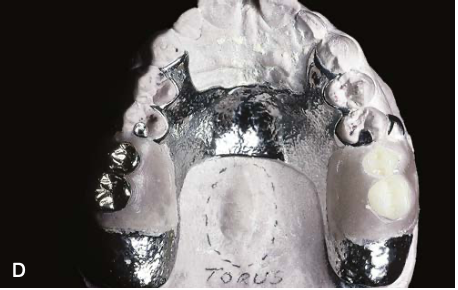
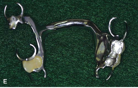
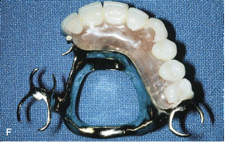
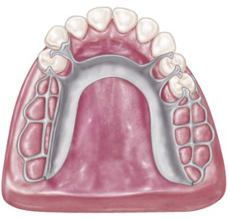
u-shaped palatal connector
multiple tooth support can make this connector more rigid
used when large inoperable palatal torus prevents palatal coverage
less desirable from patient and mechanical standpoints due to flexibility
without support borders, gingival irritation and periodontal damage can occur
can cause movement and trauma in distal extension partial dentures without tooth support
wider coverage of this connector resembles palatal plate-type connector, but lacks necessary rigidity
common error in the design of a u-shaped connector
its proximity or actual contact with gingival tissue
principal objections to use of the u-shaped connector
bulk to enhance rigidity — increase tongue-hindrance areas
fails to provide good support — allowing tissue impingement during occlusal loading
lack of rigidity — allow lateral flexure, causing torque or direct force to abutment teeth under occlusal forces
single palatal bar
centrally located between denture halves
widely used but least logical palatal connector component
objectionable from patient comfort and alteration of palatal contours
partial dentures often too thin or bulky, objectionable to the patient's tongue
must have concentrated bulk for cross-arch stress distribution and rigidity for support and stabilization
the decision to use this bar instead of a strap:
based on the size of the denture-bearing areas
whether a single connector located between them would be rigid without objectionable bulk
bar
a palatal connector component less than 8 mm in width
disadvantages of combination A/P palatal bar-type connectors
exhibits similar disadvantages as single palatal bar
the anterior bar often interferes with the tongue due to its bulk and location
these connectors could be too bulky and could interfere with tongue function
beading
exclusive of rugae areas
accomplished using cleoid carver
slightly rounded groove is preferred than a v-shaped groove
care must be exercised to create a groove no larger than 0.5 mm in width or depth
used to denote the scribing of a shallow groove on the mx master cast outlining the palatal major connector
purposes of beading
to provide a visible finishing line for the casting
to transfer the major connector design to the investment cast
to ensure intimate tissue contact of the major connector with selected palatal tissue
5 basic steps of designing mx major connectors by Blatterfein
outline of primary bearing areas — those covered by denture base
outline of nonbearing areas — those lingual gingival tissue, hard areas of the medial palatal raphe, and palatal tissue posterior to the vibrating line
outline of connector areas — provides outline or designate areas for major connector components
selection of connector type — connectors should be of minimal bulk and positioned to avoid tongue interference during speech and mastication; must have a maximum of rigidity to distribute stress bilaterally
unification — after selection, denture base areas and connectors are joined
4 factors on selecting the type of connector
rigidity
mouth comfort
indirect retention
location of denture bases
double-strap type of major connector
provides the maximum rigidity without bulk and total tissue coverage
principles in designing mx major connectors
the need for indirect retention influences the outline of the major connector
location of edentulous ridge areas influences choice of major connector strap
provision must be made in the major connector so that indirect retainers may be attached
when edentulous areas are located anteriorly, the use of only a posterior strap is not recommended
when only posterior edentulous areas are present, the use of only an anterior strap is not recommended
single palatal strap [illustration]
anterior-posterior palatal strap [illustration]
palatal plate [illustration]
u-shaped [illustration]
single palatal bar [illustration]
anterior-posterior palatal bars [illustration]
single palatal strap [illustration]
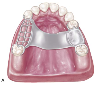
anterior-posterior palatal strap of class I [illustration]
palatal major connector covering 2/3 of the palate [illustration]
palatal plate for a class I mod 1 [illustration]
complete coverage palatal [illustration]
linguoplate [illustration]
with provisions for attaching the full-coverage resin denture base
completed rpd with resin base [illustration]
u-shaped palatal [illustration]
combination anterior-posterior palatal bar [illustration]