Nav.+Jeppsen+ATC
1/86
There's no tags or description
Looks like no tags are added yet.
Name | Mastery | Learn | Test | Matching | Spaced |
|---|
No study sessions yet.
87 Terms
Navigation
Planning, Monitoring, and Controlling the movement of aircraft from one place to another
Types of Navigation
3 types;
Pilotage
DED Reckoning
Radio Aids
Pilotage
Depends only on the PIC,
flying from point to point using Landmarks,
visually identified from the cockpit
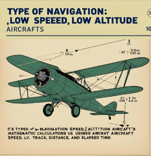
Deductive (DED) Reckoning
in Low & Slow aircrafts, by
Mathematical Calculations based on:
Speed, Distance,Track,Time.
Radio Aids
Advanced type of navigation
Based on Sending & Receiving signals From
Ground Equipment To aircraft’s Embedded Receivers. as;
1.VOR
2.DME
3.NDB
4.RMI
4.ILS
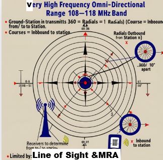
VOR
Very High Frequency Omni-Directional Range
108–118 MHz band.
Ground-station transmits 360 radials (1° apart),
Radials =Outbound From station Courses =Inbound To station.
Receivers used to determine bearing From/To the station.
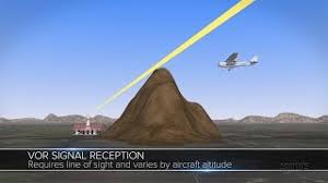
Limited by:
Line of sight– obstacles block signal.
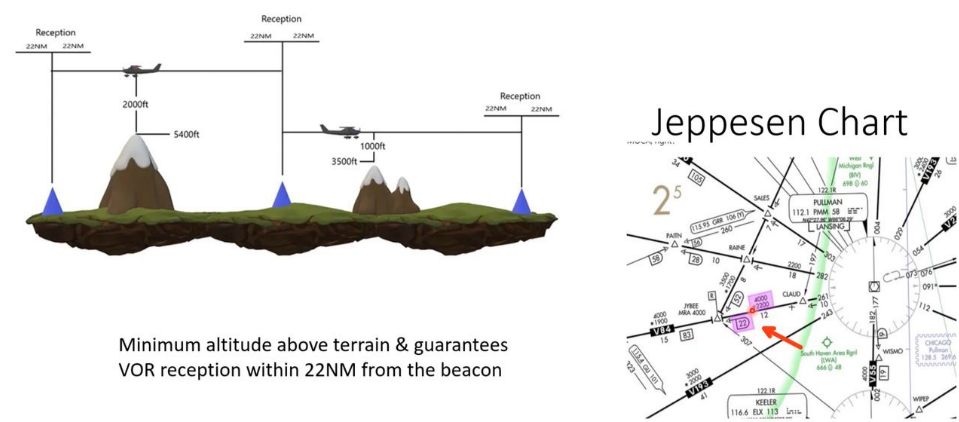
Minimum Reception Altitude (MRA)— minimum usable altitude on charts.
Usage in Flight
Common during departure, descent, and landing.
Tracked using the
CDI (Course Deviation Indicator) with
OBS (Omni Bearing Selector).
Line of Sight
Straight Line between
Transmitter and Receiver.
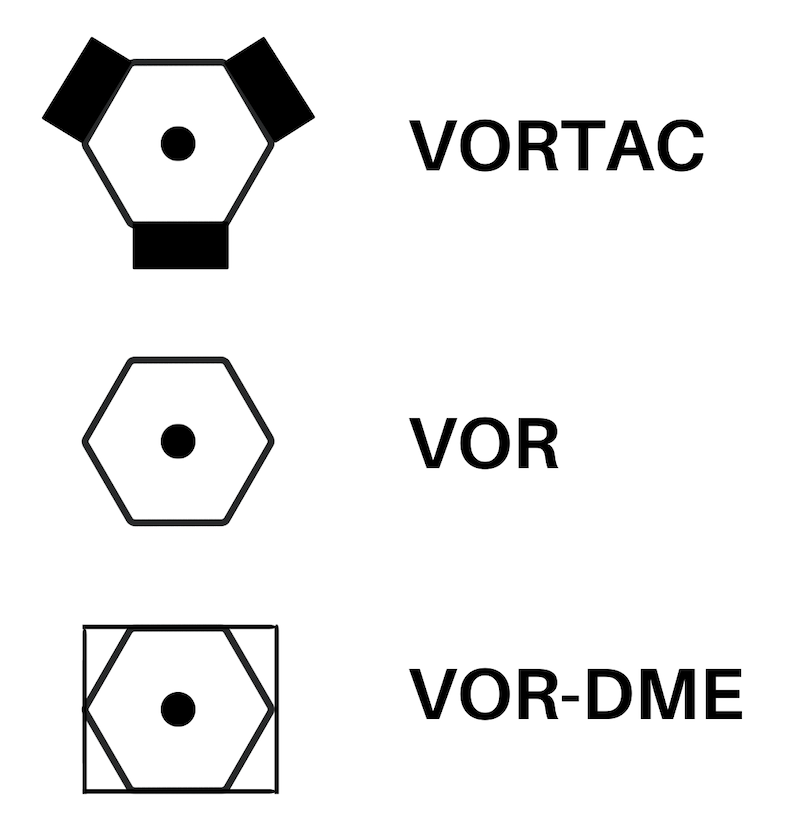
VOR Types
VOR
VOR\DME
VORTAC or TACAN
‘Tactical Air Navigation system’
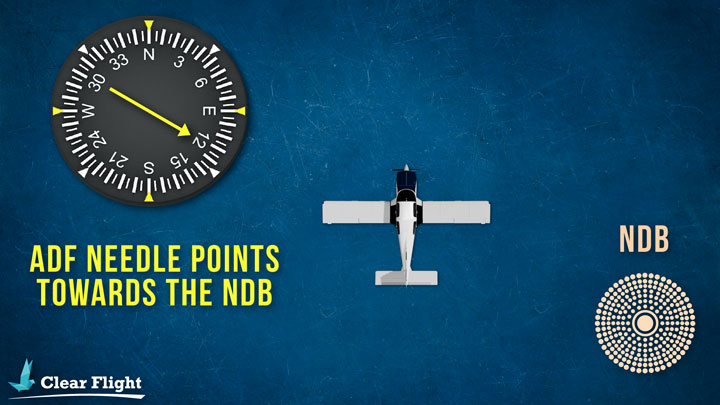
NDB
Ground-based low-frequency low cost, easy maintenance radio transmitter
Signal can propagate over terrain, unlike VOR (no need for line-of-sight)
More effective than VOR in mountainous areas
received by the aircraft’s onboard
Auto Direction Finder ‘ADF’equipment by it’s needle pointing directly to the station
CONS; Not accurate at;
Night
Shoreline
Banks
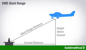
DME
Distance Measuring Equipment of the Aircraft to the Station that
Measures
-Ground Speed, Distance & Time
by Sending and Receiving Pulses
Limitations:
measuring only Slant range between them.
which is Slightly Higher than the
Actual horizontal distance.
Resulting in inaccuracy in speed and time readings when airplane is flying in any other direction than to or from the station.
When flying over the station. it reads distance based on the airplane height in nautical miles
1NM
= 6,080 Feet
MORIS Code
Call Signs as NDB's and VOR's, Pilots are required to understand this and be able to identify aircraft
VOR Volumes
T ‘Terminal’
L ‘Low Altitude’
H ‘High Altitude’
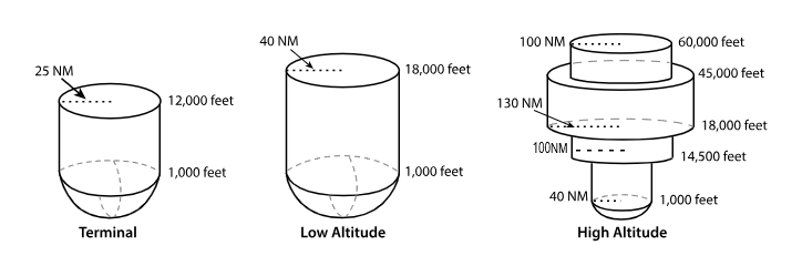
T ‘terminal’ VOR
From 1,000 feet AGL
to 12,000 feet AGL
at radial Distances out to 25 NM.
L ‘low altitude’ VOR
From 1,000 feet AGL to 18,000 feet AGL at radial distances out to 40 NM.
H ‘high altitude’ VOR
From 1,000 feet AGL to 14,500 feet AGL at radial distances out to 40 NM.
From 14,500 feet AGL to 18,000 feet at radial distances out to 100 NM.
From 18,000 feet AGL to 45,000 feet AGL at radial distances out to 130 NM.
From 45,000 feet AGL to 60,000 feet at radial distances out to 100 NM.
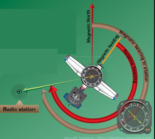
RMI
Radfio Magnetic Indicator.
simplify flying NDB approaches by eliminating the need to add magnetic heading calculations
ILS
Primary system for
instrumental approaches nowadays
Providing Lateral & Vertical guidance.
Consisting of 2 ground equipments;
Localizer
Glide slope
along with DME
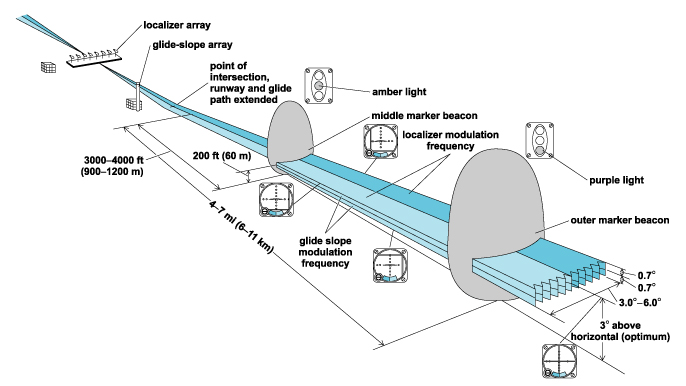
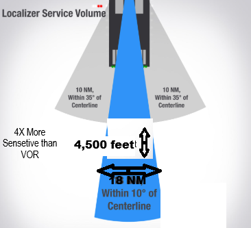
Localizer
In the Opposite End of the RW
Received Up to 18NM, & 4,500 feet
4X more Sensitive than VOR.
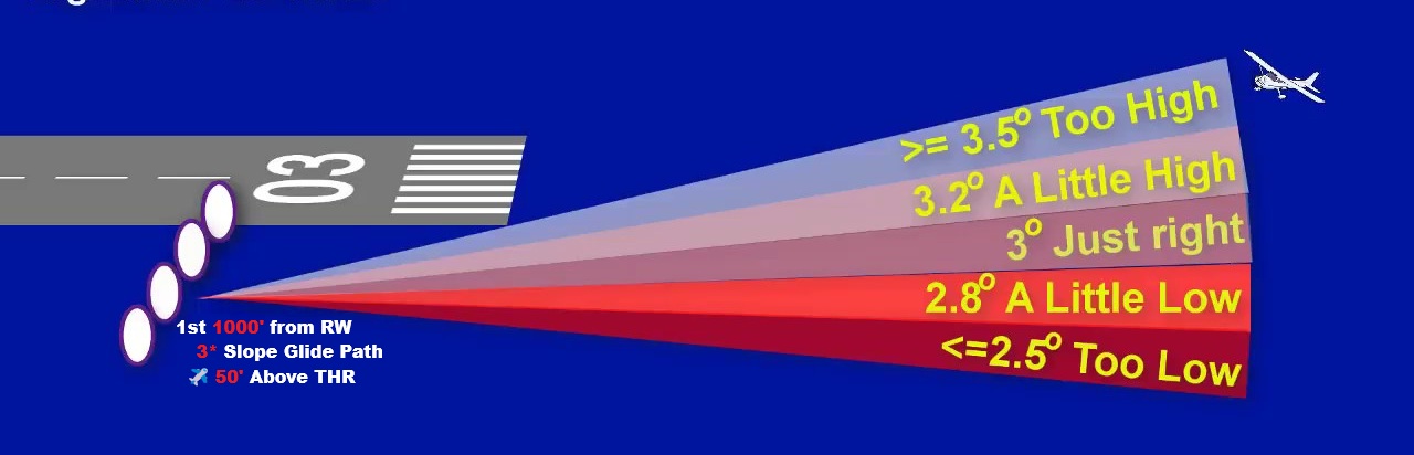
Glide Slope
Ground ‘UHF’ Ultra High Frequency transmitter.
in the 1st 1000' from RW
Displaced from the Centerline
Insuring 3° slope Glide path &
ensures aircraft is 50ft Above THR
Precision Approach
Provide Lateral and Vertical Guidance
Localizer + Glide Slope
ex. ILS app,
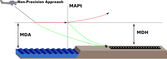
Non-Precision Approach
Provide Lateral Guidnance only,
VOR app,
Localizer app,
NDB app,
RNAV app
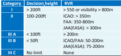
ILS Categories
CAT I
CAT II
CAT III; A, B, C
Based on; Visibility, Decision height, & RVR
CAT I
(DH>200ft)
Decision Height Not Less Than 200 feet
(RVR>550m)
RVR Not Less Than 550 meter
CAT II
-(100>DH>200ft)
Decision Height Less than 100 But Not Less than 200 feet
-(RVR>300m)
RVR Not Less Than 300 meter
Company’s Policy
PF & PM Validated for CAT2 approach on license.
CAT2 Equipped & Approved Aircraft & Runway.
CAT III
3 Types: Alpha, Bravo, Charlie
No Decision
No RVR
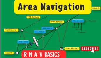
RNAV
AREA Navigation System,
Allowing
aircraft to fly Directly to the Waypoint without passing over Ground Equipment.
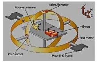
INS
One of the initial systems Enabiling RNAV.
Inertial Navigation System, Self Contained
Detecting plane’s motion and
Indicates its displacement by using
Accelometer to know Speed
Gyroscope to know Heading
INS updates position from the Last known location.
small errors accumulate over time due to speed/time miscalculations
Corrected by IRS
IRS
The Inertial Reference System
Using Laser Gyros reducing the noise
results in overall reduction of drift
Having its own database saving the aircraft Motion and Comparing it to the Initial position not using the last position.
RNP
Required Navigation Performance
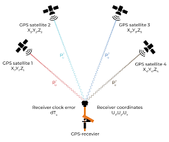
GPS
Global Positioning System:
Part of the Global Navigation Satellite System (GNSS).
used to be 24 now, 33 satellites in orbit, operating in 6 orbital planes.
Requires
3 satellites for 2D position
4 or more satellitesfor 3D position uses
Accuracy affected by signal delays due ionosphere/troposphere.
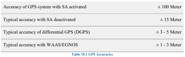
Enhancements:
SA (Selective Availability): Removed to improve accuracy.
DGPS (Differential GPS): Uses ground stations for ±5m accuracy.
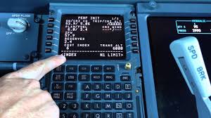
FMC
💘 of flight manegment system providing
Centralize Control for
Navigation and Preformance managment
FLP is Loaded on it before flight calculating;
Aircraft’s Position
Fuel Consumption & ETA
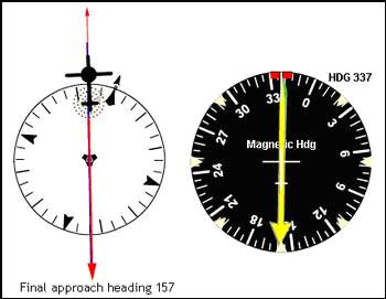
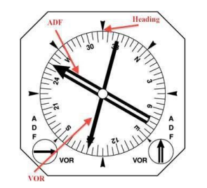
HSI
Horizontal Situation Indicator
Reduce Pilot’s Monitoring Workload
by Combining 4 Indicators in one Panel
Heading,
VOR,
ADF,
ILS,
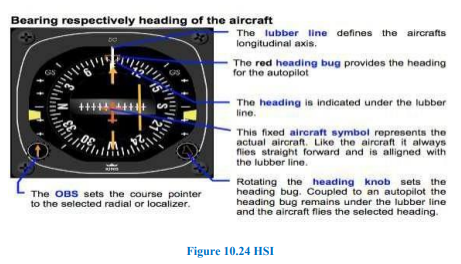
RMI
Radio Magnetic Indecatior
Displays two VORs or two ADFs or a combination of both,
Along with Heading.
Climb Gradient Calculations
Rate of Climb =
Gradient in % × GS
Descent Calculations
The required distance to run =
(altitude ÷1000 × 3)+10
For every 3 knots Headwind -1 nm
For every 3 knots Tailwind +1nm
Leading Radial
where craft starts its turn to
Intercept its intended course
the Heavier & Faster the craft is
the Earlier it will start Turning.
3 Approaches
LDA, MLS and SDF, APPROACHES
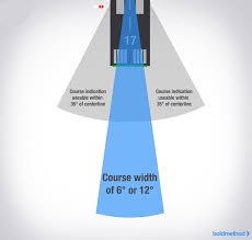
(SDF) Simplified Directional Facility
Providing final approach course similar to an ILS localizer.
Course width is at 6° or 12° for optimal approach quality
may not align with the runway & less precise than an ILS.
Usable indications are within 35° of the course centerline.
Indications beyond 35° are uncontrolled and should be ignored.
The antenna may be offset, with a convergence angle ≤3°written in approach chart.
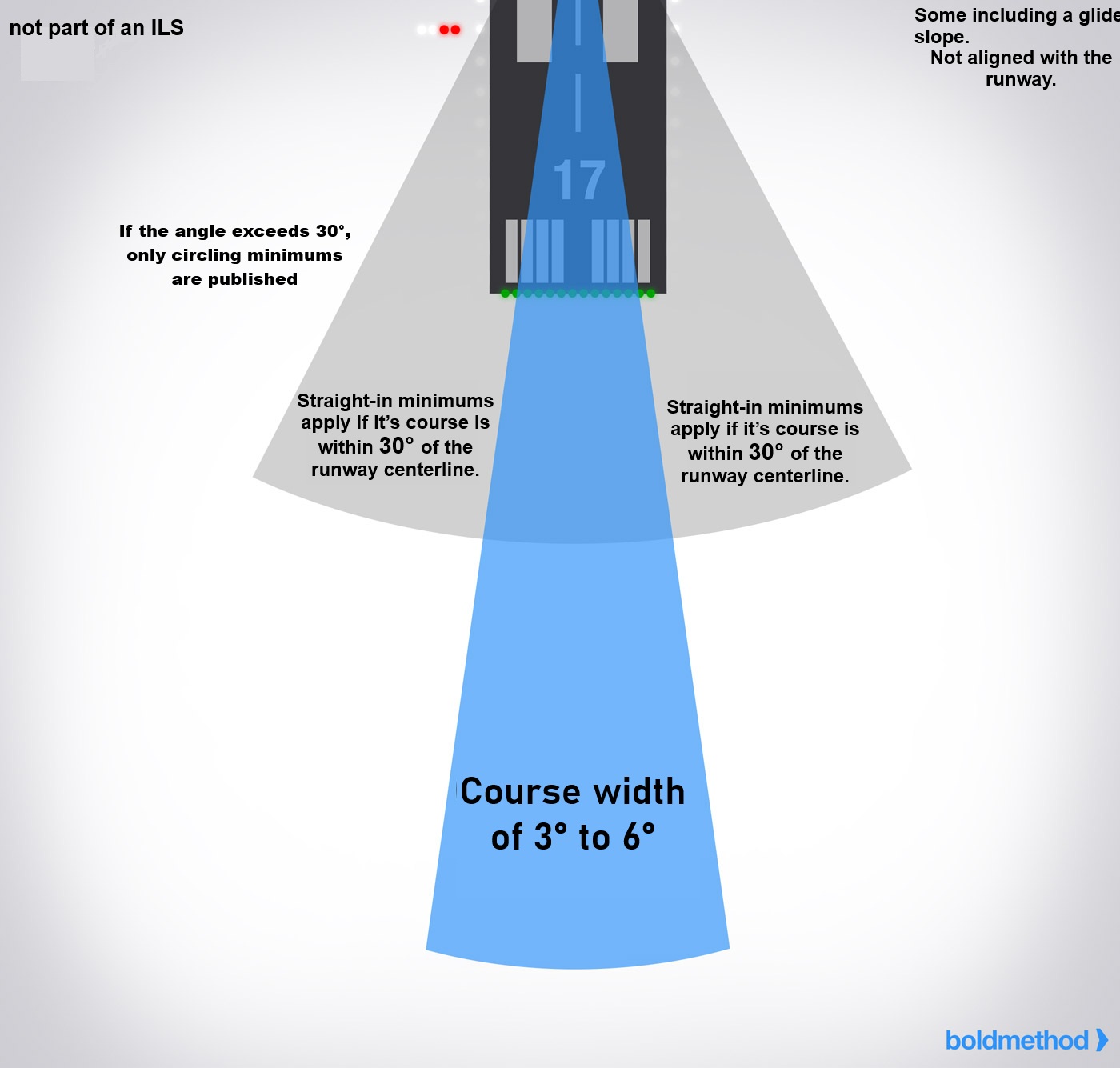
(LDA) Localizer Type Directional AID
Similar in accuracy to a localizer but not part of an ILS.
Course width is 3° to 6°, more precise than SDF.
include Glide Slope.
Not aligned with RWY.
Straight-in minimums applyif course within 30°
of RWY Centerline.
If the angle exceeds 30°, only Circling minimums are published.
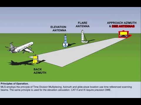
(MLS) Microwave Landing System
provides Precision approach guidance.
It offers, elevation (glide slope), and range information.
Guidance is displayed on CDI (Course Deviation Indicator)
or multifunction cockpit displays.
Requires specialized airborne equipment not commonly found in general aviation.
Includes data communication for system status, weather, and runway information.

VASI
Visual Approach Slope Indicator (VASI) provides visual descent guidance using two wing bars (upwind & downwind).
On slope: Upwind bar red, downwind bar white.
Too high: Both bars white.
Too low: Both bars red.
Some airports have three-bar VASI for large aircraft.
PAPI
Precision Approach Path Indicator (PAPI) provides visual descent guidance like VASI.
Uses a single row of lights, usually on the left side of the runway.
TRI-color
Tri-Color System provides visual approach guidance using a single light unit.
Red indicates below the glide path.
Green indicates on the glide path.
Amber indicates above the glide path.
A dark amber zone exists below the glide path but should not be mistaken for an "above" indication.
Pulsating Visual Approach Slope Indicator
uses a single light unit for visual guidance.
On glide path: Steady white light.
Slightly below glide path: Steady red light.
Further below glide path: Pulsating red light.
Above glide path: Pulsating white light.
Pulsating rate increases as the aircraft moves further above or below the glide slope.
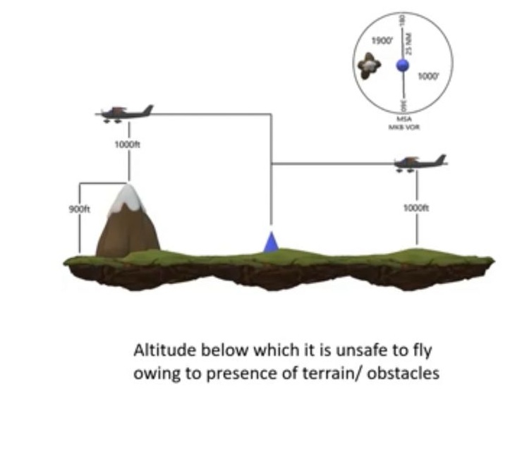
MSA
Minimum Sector/Safe Altitude
lowest altitude which may be used
Under Emergency, providing
minimum Clearance of
1,000’ above all obstacles
within a sector of
25 NM radius
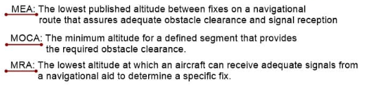
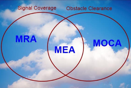
MRA (Minimum Reception Altitude)
Minimum altitude on an Airway Segment
Between 2 Radio Fixes
Assuring:
Acceptable Navigational Signal Coverage.
MAA
Maximum Authorized Altitude.
Hightest Alt. On airway segment
Assuring MRA
MOCA
Minimum altitude on an Airway Segment
Assuring:
Obstacle Clearance Requirements.
with a radius of 22NM
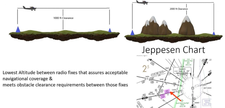
MEA (Minimum Enroute Altitude)
Minimum altitude
Between 2 radio fixes
Assuring;
MRA & MOCA
MCA
Minimum Crossing Altitude
Lowest Alt. at which Radio fix Could be crossed or continued along
Assuring MOCA
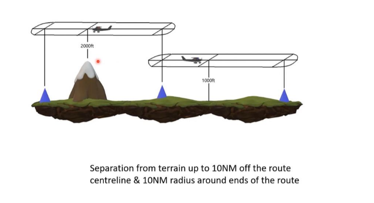
MORA
Minimum Off-Route Altitude
Provide obstacle clearance
1000’ in nonmountainous and
2000’ in mountainous areas
within
10 NM on both sides & 10 NM Radius around the Ends
of the airway.
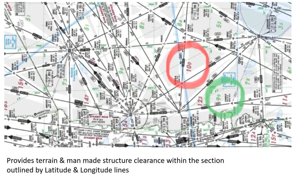
Grid MORA
provide an Obstacle Clearance altitude within
Latitude & Longitude Grid Block.
(IAF) Initial Approach Fix
Beginning of Initial approach segment, where Instrument approach segments begins,Usually (VOR, NDB, DME, etc.)

Intermediate approach fix
Configuration & Speed are Adjusted to
Prepare & Position
AC for Final Descent @ AP

(FAF) Final Approach Fix
Marked By
Maltese Cross in Non-Precision approach,
Glide Slope Intercept in Precision app.
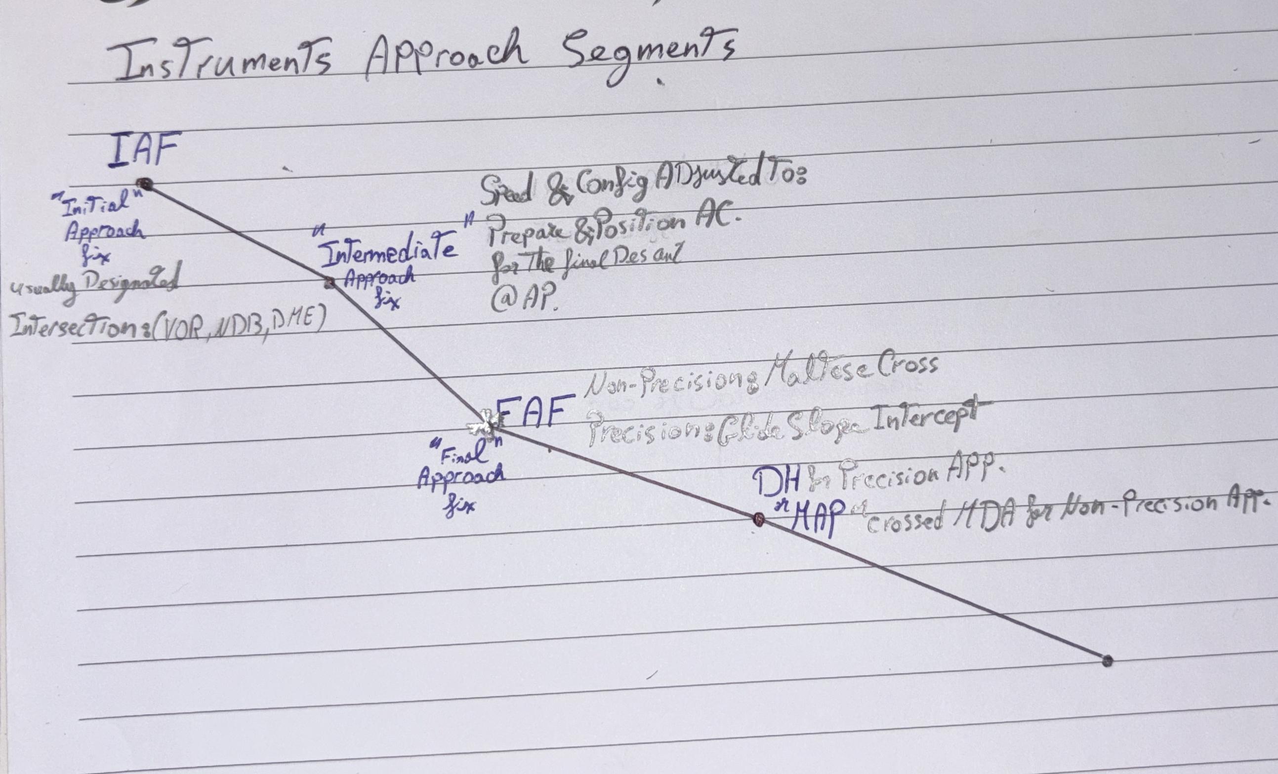
(MAP) Missed Approach Point
Beginning of Execution of
Missed Approach Procedure if required.
Marked By;
MDA in Non-precision approach
DH in Precision approach

Desicion Altitude (DA)
Specified Alt. referenced to Mean Sea Level (MSL)
in Non-Precision Approach where
Missed Approach must be initiated if
required visual reference Not established.
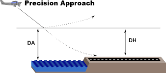
Desicion Height (DH)
Specified Height referenced to Threshold Elevation (THR ELV). in
Precision Approach where
Missed Approach must be initiated if
required visual reference Not established

Minimum Descent Altitude (MDA) or
Minimum Descent Height (MDH)
Specified Altitude or Height in a
Non-Precision Approach or
Circling Approach below which
Descent must not be made without
required visual reference.
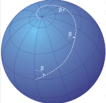
Great Circle Route
Shortest Route Between 2 points on a Sphere
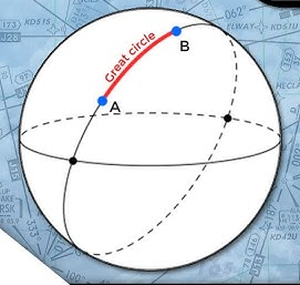
Rhumb Line
Curve Crossing each Meridian at the
Same Angle.
Cloud Base
Height of Lowest layer of clouds
Few Or Scattered
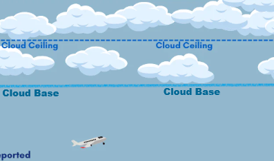
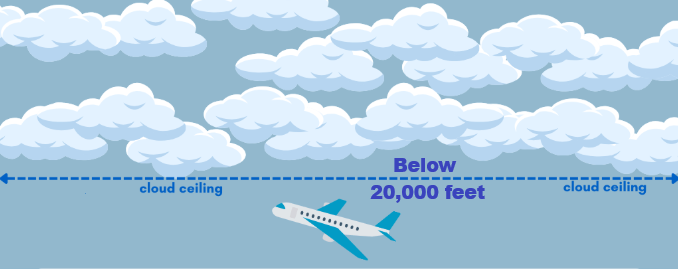
Cloud Ceiling
Height of Lowest layer of Clouds
Covering more than half the sky
Broken or Overcast
Below 20,000 ft
Air Traffic Control Service (ATC.S)
provides
Aircraft Separation,
Traffic Instructions,
Clearances,
helps Stop collisions.
It has three levels, based on where the aircraft is:
Aerodrome Control Service (Tower)
Controls ground and runway movements.
Takeoff and landing clearances are given here.

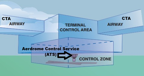
Control Zone (CTR)
Controlled airspace extending from Surface of the earth to Specified Upper Limit
Handles arriving or departing aircraft around airports (like 2,500 ft AGL).
Guides aircraft for approach sequencing and descent.

Control Area (CTA)
Controlled airspace starting from a Specified altitude upwards
Manages enroute traffic between airports (cruising at high altitude).
Covers wide regions like FIRs.
FIR
Flight Information Region; a controlled region of sky where one ATC authority is in charge.
🔹 Provides FIS and ALR.
FIS
Flight Information Service
Gives you info like weather, NOTAMs (like closed runways), traffic around you.
Especially important in uncontrolled airspace (no ATC).
ATAS
Air Traffic Advisory Service
It advises about traffic to avoid potential conflict.
But it doesn’t issue Clearances.
Usually applies to IFR Uncontrolled airspace.
Danger Area
🔸 Activities dangerous to aircraft may exist (e.g., military firing).
🔸 Not always active — check NOTAMs.
Restricted Area
🔸 Flying is allowed only under certain conditions.
🔸 Might require clearance or only be open at certain times.
Prohibited Area
🔸 No aircraft allowed under any circumstances.
🔸 Usually for national security ( presidential palace).
⏱ 1. TOTAL ESTIMATED ELAPSED TIME (TEET)
Estimated time required
📍 Starts: At T/O
📍 Ends: At a Designated point in the flight plan
🛬 TOUCHDOWN ZONE ELEVATION (TDZE)
Highest point in the first 3000’ of runway (measured from THR), affects:
Precision approaches (ILS)
Minimums during landing
☁ VOLMET
Continuous Radio Broadcast for Major airports during Cruise, Giving only
Meteorological conditions (Weather)
📻ATIS – Automatic Terminal Information Service
Continuous Radio Broadcast For Busy Airports, before contacting ATC. Giving;
Weather (wind, temp, visibility)
Active runway
Type of approach in use
NOTAMs or closed taxiways
📅CTOT / SLOT TIME / ATFM SLOT
👉 A time issued to your flight to keep traffic flowing smoothly through FIRs and airspace sectors.
⏳ You must take off within a window:
🟰 −5 min to +10 min from the CTOT
(Otherwise you’ll need a new one)
🧮 Formula:
CTOT = EOBT + Taxi Time + Any Delay
EOBT = Estimated Off-Block Time
(When you expect to push back from the gate)TT = Taxi Time
(How long it takes to taxi to the runway)
RVSM
Reduced Vertical Separation Minimum
Reduction From 2,000 to 1,000
of standard vertical separation if AC is equipped & Pilots are Verified to Handle it
Between FL290➡FL410
Flight Level Orientations
for IFR
0* to 179* must be Odd
180* to 359* must be Even
for VFR
same as IFR with adding 500’ to all levels
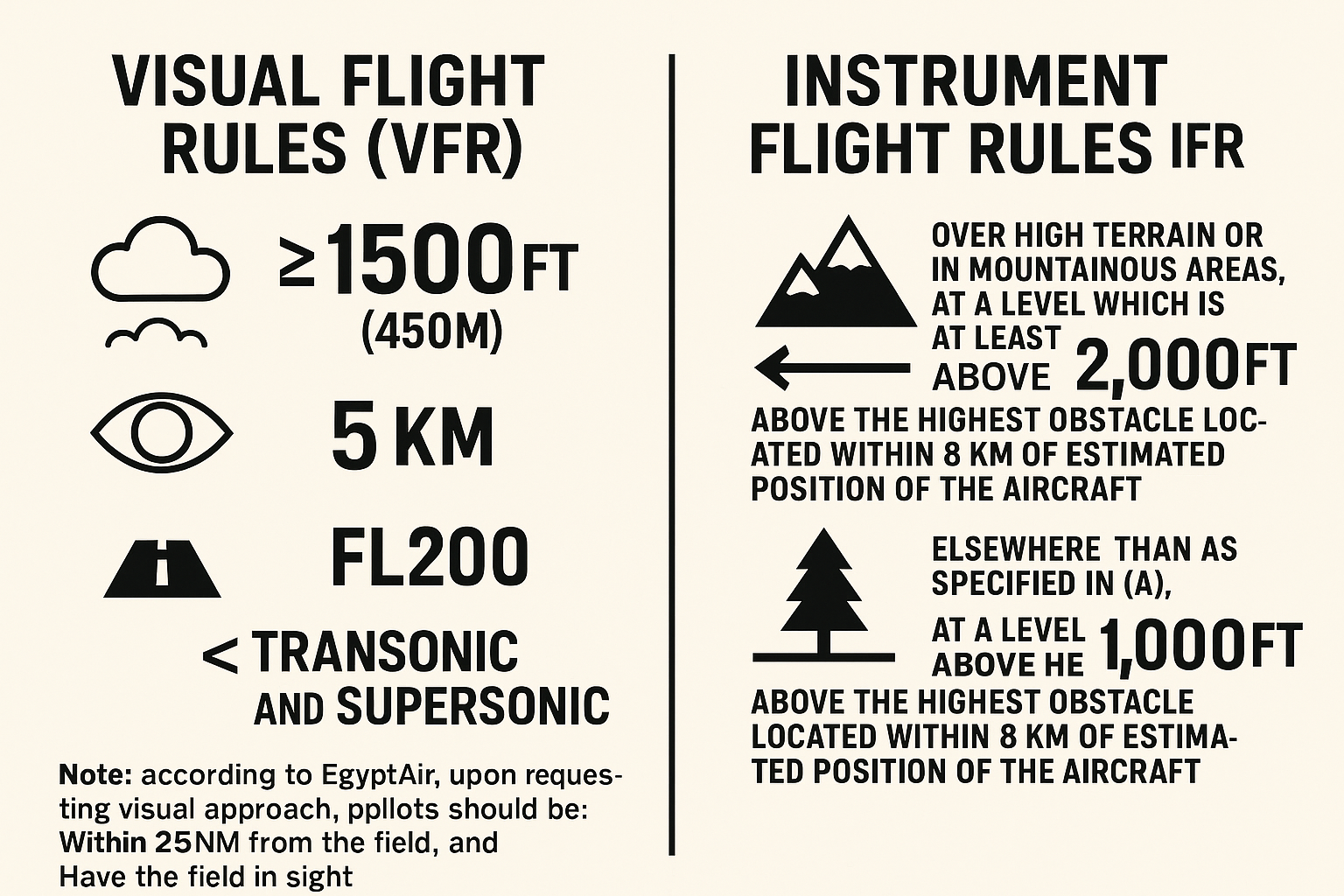
VFR (Visual Flight Rules)
Ceiling>1500’
Flight Level <FL20
Visibility> 5 km
Speed <Trans/Super-Sonic
Field in Sight & Within 25 NM from it
According to Egyptair.

IFR (Instruments Flight Rules)
in Non-Mountanius,
at least 1000’ above highest terrain
in Mountanius,
at least 2000’ above highest obsticle
Within 8 Km of AC Position
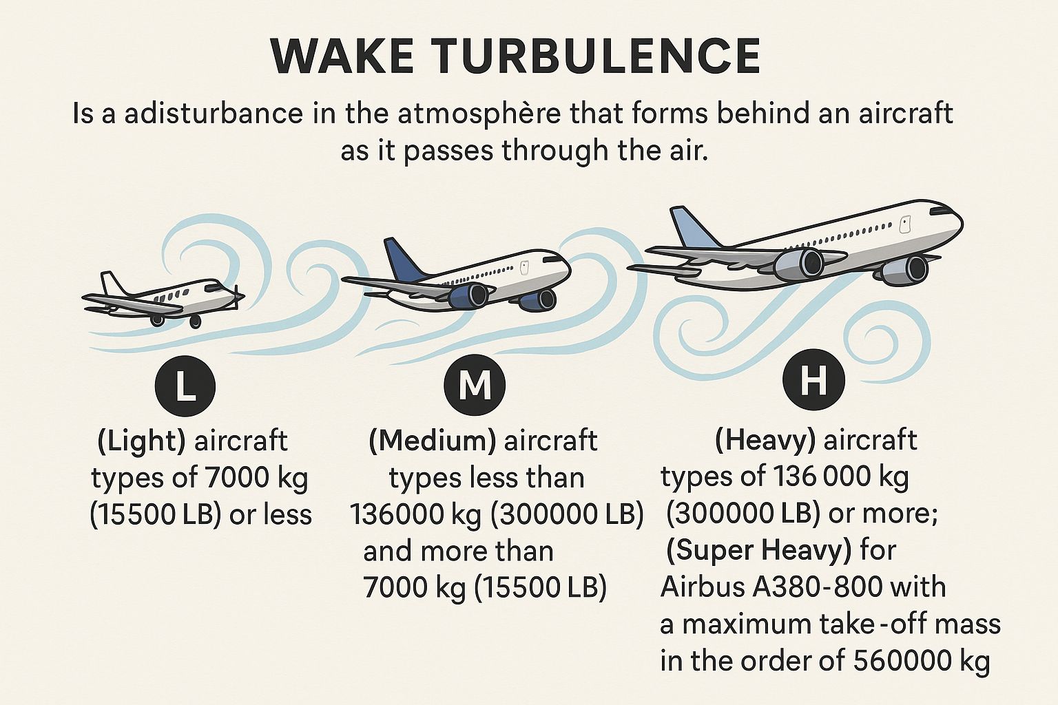
Wake Turbulence
disturbance in the atmosphere that forms behind an aircraft as it passes through the air
Transponder emergency Codes
7500: “Seven-Five, man with a Knife."
7600: "Seven-Six, radio needs a Fix."
7700: "Seven-Seven, going to Heaven." Corresponding to emergencies:
- 7500: Hijacking
- 7600: Communication failure
- 7700: General emergency
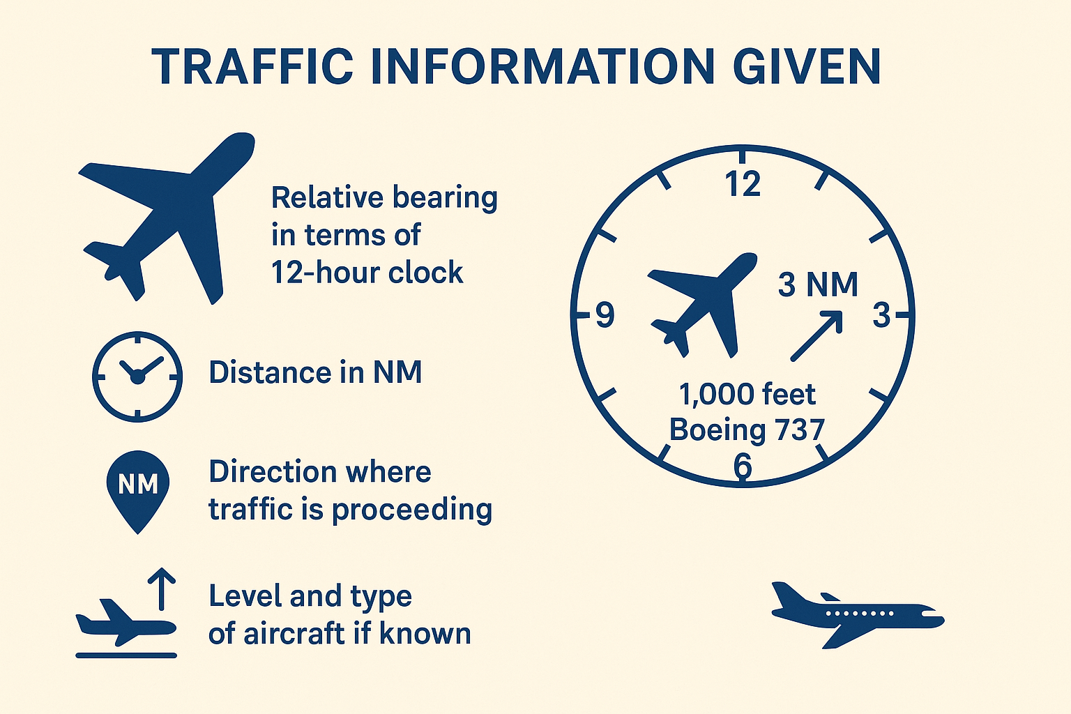
Traffic Informations Given
🕒 Relative Bearing (12-hour Clock Format)
Indicates the direction of the traffic relative to the pilot’s heading.
📏 Distance
Given in nautical miles (NM).
Indicates the distance to the conflicting traffic.
➡ Direction of Movement
Indicates the direction of the traffic relative to the reporting aircraft.
🛩 Level and Aircraft Type (if known)
Altitude/flight level of the other traffic.
Type of aircraft, if identified.