CHEMMAT 121 EXAM PREP
1/127
There's no tags or description
Looks like no tags are added yet.
Name | Mastery | Learn | Test | Matching | Spaced |
|---|
No study sessions yet.
128 Terms
Strength
Amount of force (stress) a material can resist before failure (permanently deformed and fractured
Stress
Sigma, Force over cross sectional area. Area decreases stress increases. Unit Pa or Nm-1
Strain
Change in length over original length. No unit or %
Tensometer aka Instron
Used to characterise mechanical properties. Measures F and change in length as material is pulled
What does the linear section of a stress-strain curve represent?
Elastic deformation, All strain is recovered upon unloading and stress < yield stress
What happens after yield stress but before UTS?
Plastice deformation (work hardening) and eleastic deforemation. Uniform reduction in area, some permanent dedformation when unloaded, but also some recovered.
What happens past UTS?
Necking, forms local reduction in area (neck). Still elastic deformation
What happens at fracture point? Stress-strain curve
! piece becomes more than one piece, and a gap forms, eleastic deformation is still recovered.
Youngs Modulus.
E, stiffness. change in stress/ change in strain. Unit is Pa. It is the gradient of the eleastic deformation section.
What is special about fully annealed steel stress strain curve?
Once yield stress is readched there is a discontinius yield before the graph continues. This only happens once, as the steel work hardens past this point.
Poissons ration
represented by "neu"(v). (-)strain in x axis/strain in y axis. Ratio how thin a metal needs to be when stretched by a certain amount. Most metal and polymers v = 0.5.
0.2% Proof stress
Geometric tool to use if there is no obvious yield point. Move gradtion line 0.2% (0.002) and take yield point as where the lines cross.
Safety Factor.
Either pretend material weaker than it is OR applied force bigger than it actually is. E.g. for SF of 4 w/100N force either 100 x 4 = 400N force OR yield stress = actual yiels stress / 4.
Engineering stress vs true stress
Egnineers only operate in eleastic def area. True stress is F/Instanaous area. engineering stress is F/init area. true stress increasess exponentially at UTS.
Ductility
How much plastic def before fracture. Described in:
%Elongation (%EL) = ΔL/init length * 100%.
%Reduction in Area(%RA) = ΔA/init A * 100
Toughness
Energy required to fracture a material. aka, area under the curse. unit: J/m^3 Usually something string is not tough.
BCC
Body Centered Cube:
atoms per unit cell: 2
Co Ordination number (how many atoms 1 atom is touching): 8
Unit Cell Dimension (a) = 4R/sqrt(3)
Atomic Pakcing Factor: 68%
E.g. chronium
Atomic Pakcing Factor
Vol of atoms/Vol of unit cell. aka hwo effciently unit cell filled with atoms. e.g. BCC 68% atoms 32% sea of e-
FCC
Face Centered Cube:
atoms per cell: 4
Co-ordination num: 12 (max possible)
-Unit cell dimension(a) = 4R/sqrt(2)Atomic Pakcing factor: 74%
FCC is close packed structure.
E.g. Copper
HCP
Hexagonal close packed:
atoms per unit cell: 6
-Co ordination num: 12
-Atomic Packing Factor: 74%
E.g. MAgnesium
Polymorphism
Materials have more than one structure. e.g.
IRON at RT = BCC
Iron at 912 degress = FCC
Ceramics
metals + nonmetals bonded ionic and covanlently. Arranged Crystalline.
Can be either Rock salt or Silicate Structure.
Determined by Balanced charges, relative size of ions (cations < anions. ions dont touch ion of same charge.)
Rock Salt
Two interlocking FCC structures.
Co ordination num = 6
a = 2(Radius anion) + 2(Radions cation).
Has ionic and covalent bonds, no sea of e- to conduct heat therefore thermally insulated.
Silicate (SiO4(4-))
Building block for rocks, soils, clays, sand. Base SiO4 join w/each other. NOT UNIT CELL.
Glasses vs ceramics
When atoms NOT regular repeating pattern (amporphus) form GLASS. When they ARE (crystalline) formm CERAMIC.
If SiO4 structure….
COOLED SLOWLY -> time atoms to rearrange -> CRYSTALLINE
COOLED RAPIDLY -> no time atoms rearrange -> AMORPHUS
Naming directions
[u v w] <- direction
1) Draw vector for direction (origin @ start)
2) Project Length onto unit cell axes
3) Put in terms co effcients
4) Convert to integers (double for 1/2)
5) put in aquare brackets.
For -ve directions put bar over num.
If spacing in one direction = another CYSTALLOGRAPHICALLY EQUIVALENT. e.g. BCC and FCC since both cubes
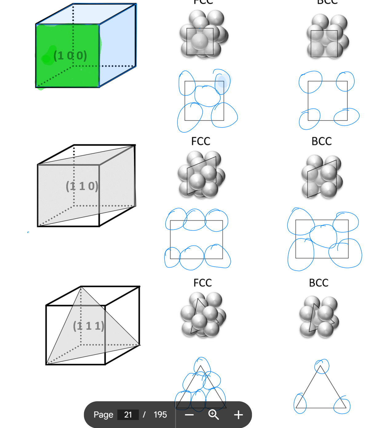
Naming Planes
(h k l) <- round brackets
1) Pick origin NOT on plane, usually plane is like roof to origin point
2) Work out intercepts (can be inf if // to axis)
3)Take reciprocals (e.g. 1/inf = 0)
4) Convert to integers if needed (1/2/ -> 2)
5) put in round brackets
What cases plastic & elastic def.?
ELASTIC → atomic bonds stretching
once past yield stress further def is permanent. This is caused by SLIP.
Slip
atoms sliding past each other, “block slip model”.
Close packed plane → less distance to next position → WEAKER material
Non-close packed plane → more distance to move → stronger material
Theoretical strength
Calculated energy req to break/make bonds.
ALWAYS LESS than measured strength due to IMPERFECTIONs.
In metals : dislocations
In ceramics: porosity
Point Defects
Vacancy → gap where atom should be
Interstitial atom → smaller in between other atoms
Substitutional atom → diff element than lattice.
Planar defects
aka dislocations
Edge dislocation → extra half plan in lattice
Screw dislocation → twist in lattice
Slip & dislocation movement
dislocation movement makes slip easer → bcuz of dislocations → bonds only need to break one at a time
This takes less energy/work → much weaker —> slip occurs easier
Slip can be thought of as dislocation movement w/in a lattice
Slip systems
occurs most easily on close packed planes in close packed directions.
e.g. BCC stronger than FCC as slip occurs easier.
FCC main slip system: {111} <110>
BCC main slip system: {110} <110>
Hcp has close packed planes BUT plane all in one orientation so slip very difficult → HCP metals very brittle (strong).
Ceramics & Glass properties
Ceramics:
Brittle, plastic def. improbably as when slip occurs cations line up together and repel
Stiff, due to strong ionic/covalent bonds
Glass:
very strong
very brittle
low toughness
Solidification
Polycrystalline → many crystals (molten metals solidify)
NOT ACCURATE: over decreaing temp, increasing time
baby crystal nuclei → nuclei grows each nucleus a single crystal, grain → keep growing bigger
EQUIAXED GRAINS → grains roughly equal
Homogenous Nucleation: solid in liquid
Hetrogenous Nucleation: with mould wall for solid to form on MORE COMMON
Grain Boundaries
Mismatch in lattice orientation → surface atoms have free bonds → bulk atoms formed all bonds → GB’s are high energy regions due to the surface atoms having free atomic bonds.
Grain structure development
“chill” cyrstals, small equiaxed grains on walls
Then columnar grains.
In the middle:
equiaxed grains OR columns meet OR hole/pore OR dendrite formation
The middle section makes the metal anisotropic (not the same in all directions).
How to get equiaxed structure?
use grain refiners (e.g. adding Ti particles when casting Al)
Annealing (heat treatment)
Metallography
Reveals Grain boundries
Grinding w/ sandpaper → removes big scratches, flat surface
Polishing w/diamond paste → removes more scratches (mirror like surface)
Etching w/ acid/alkali → reveals GBs
Polished metal → all light reflected so GBs not visable
Etched metal → GBs scatter light so they appear as dark.
Grain boundaries & dislocation movement
GBs stop dislocation movement bcuz of discontinuity in planes → makes material strong (but less ductile)
Big grains → fewer GBs → less GB density → weaker & more ductile
Small grains → more GBs → higher GB density → stronger & less ductile
Hall-Petch effect
yield stress = constant (friction stress) + k (hall-patch constant) * d(grain size mm)^(-0.5)
how GBs affect strength
Work Hardening
Metal plastically deforms and becomes stronger:
dislocations move → multiple → dislocation density increases → inhibit each others movement → creates “traffic jam” → material is stronger but less ductile.
Aka cold working as plastically deformed below recrystallisation temp.
Cold working equations
Rolling:
% CW = (init thickness - new thickness)/init thickness * 100%
Assuming width doesn’t change much
Extruding:
%CW = (init area - final area)/init area *100%
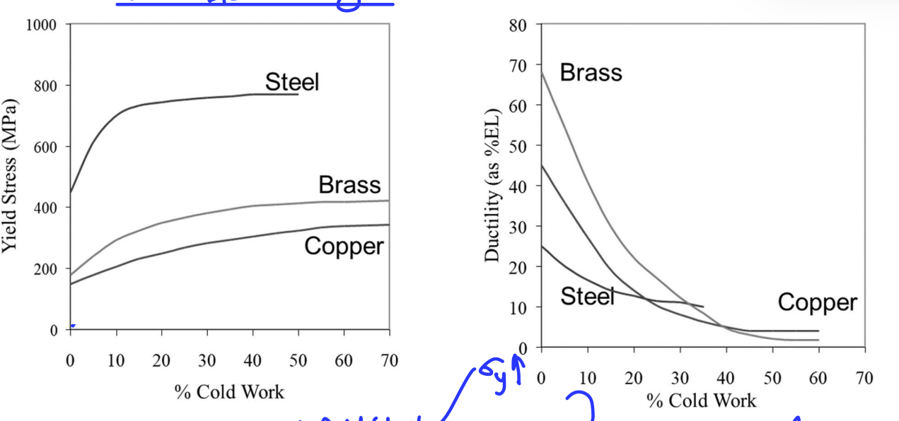
As %CW increases, yield stress increases and ductility decreases
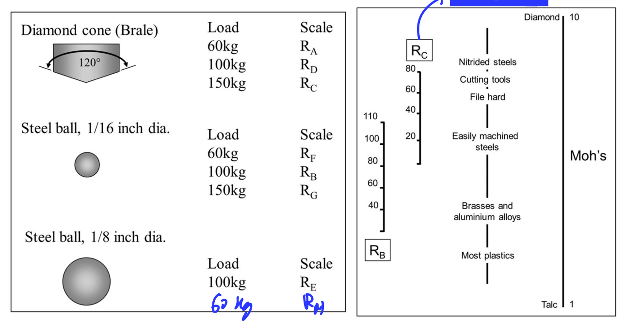
Hardness
Resistance to localised plastic deformation.
Use indent test indenter must be harder than tested material.
Harder material → small indent
Hardness proportional to strength, not equal to strength
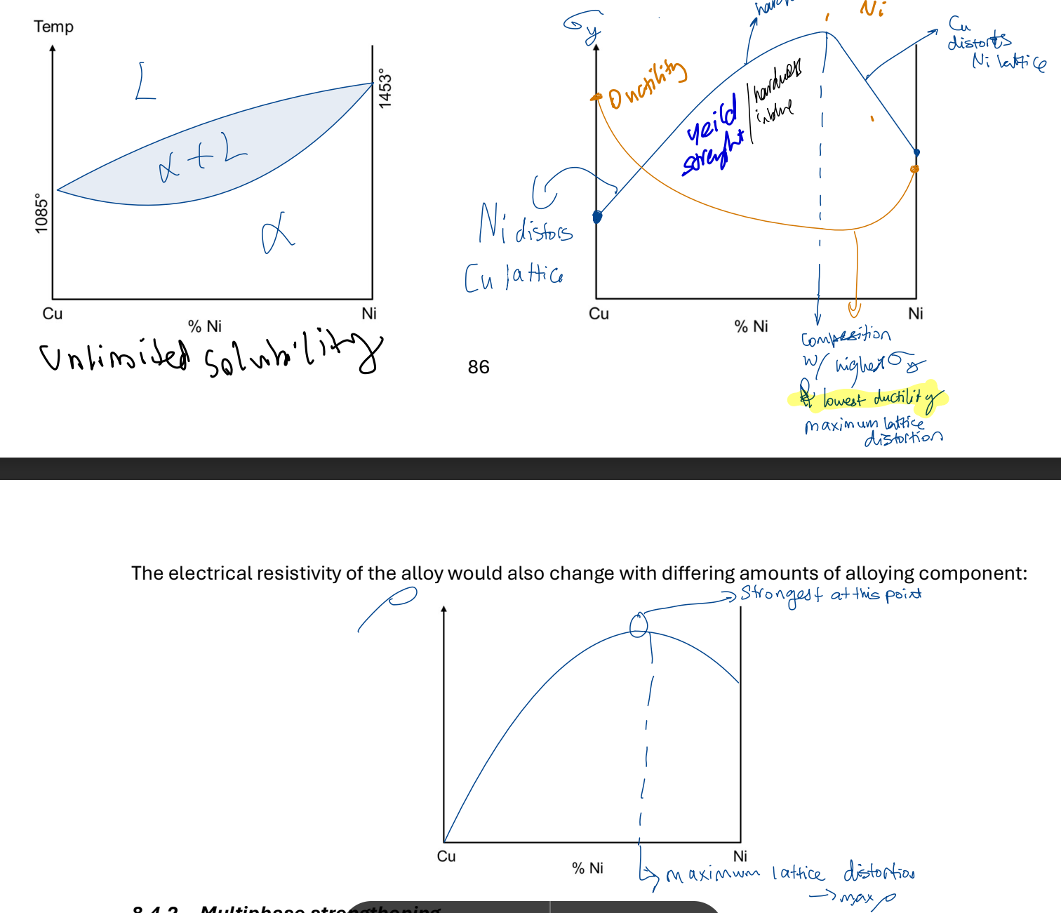
Electrical properties
V = IR, R depends on material but NOT property
Resistivity (p) is a property p = R*A/L unit ohms meters
Metals good conducters → sea of e-
e- move → hit +ve core → stop (attracted by +ve) → resistivity INCREASEs
Ceramics + glass good inductors
no sea of e- → no e- movement
Electrical conduction in metals
On the graph electron drift velocity vs time:
Increases linearly until it hits a positive ion core, then falls, before repeating.
Middle is avg drift velocity. Vd = electron mobility (function of collision rate affected by atomic spacing) μ * electrical field strength
Electrical Resistivity in metals
Resistivity never 0, due to residual resistivity due to imperfections.
@ low temp:
less thermal vibrations
less resisitivity (less collisions)
@ high temp:
more thermal vibrations
more resistivity (more collisions)
While linear:
total resisitivity = resisitivity @ 0 * (1 + temp coeffcient * Temp)
CW vs Resistivity
Increasing CW → Increasing dislocations → resistivity (more collisions)
Linear relationship as %CW increases, but DOESNT start at 0.
Annealing
heat treatment @ 2/3 melting temp, reverse effects of work-hardening
elongated grains (more dislocations, resistivity) strong and brittle.
THEN ANNEALING
equiaxed grains (less dislocations, resistivity) weak and ductile.
Annealing steps
Recovery
dislocations rearrange to lower energy config.
dislocation density unchanged. goes from pile up/traffic jams → spread out arrangement (less energy)
Recrystallisation
New grains (less dislocation density & equiaxed) nucleate at pre-existing grain boundaries. new gains grow @ GBs → when new grains meet → recrystallisation. Thermodynamic driving force: stored strain energy, from high energy state to low energy state.
Grain Growth
nucleated new grains grow bigger. goes from high energy small grains to low energy big grains. Thermodynamic driving force: reduction in GB energy.
How does annealing change metal properties?
RECOVERY:
strength and ductility constant
Resistivity decays exponentially
RECRYSTALLISATION:
strength decreases linearly (new grains w/ less dislocations)
ductility increases linearly
resistivity decrease exponentially but slower than before
GRAIN GROWTH:
all keep continuing lines, plateuing of. Strength due to hall-petch effect.
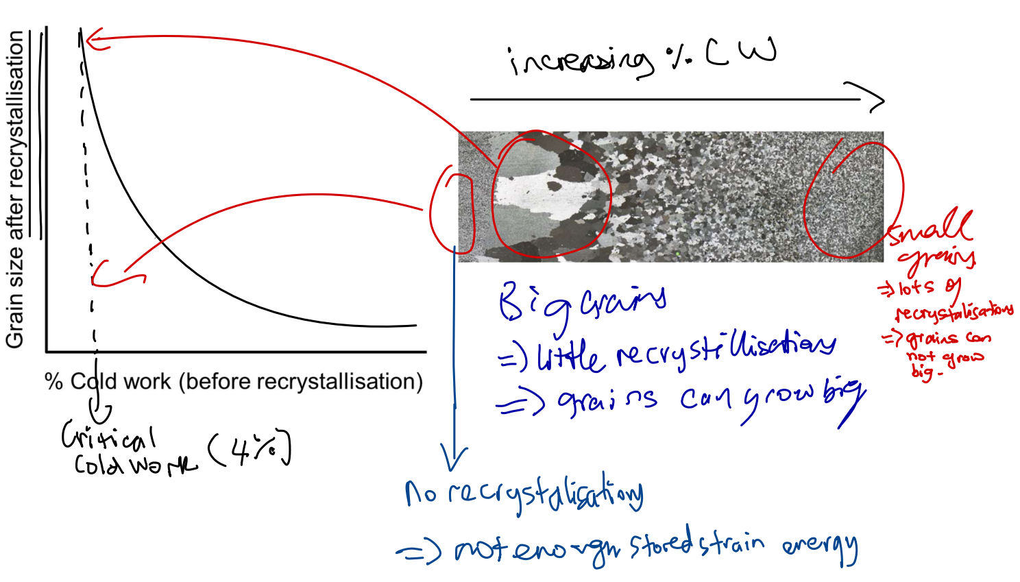
Rate of Recrystallisation
Increasing temp increases rate of recrystallisation.
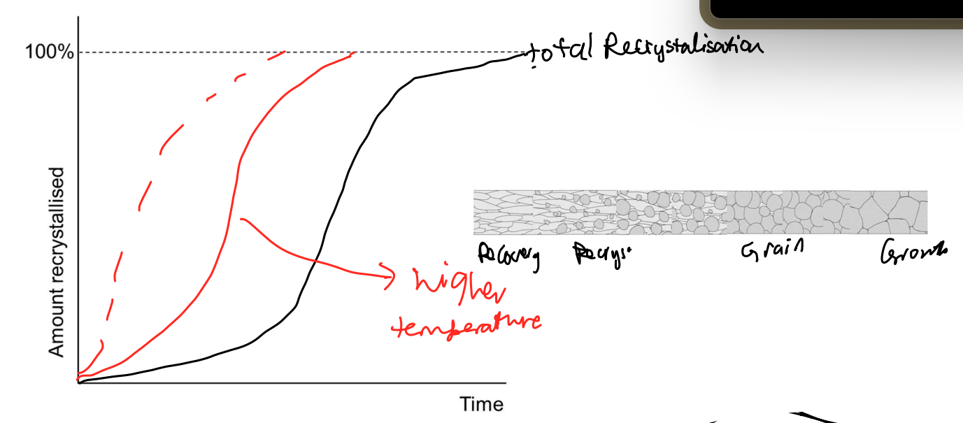
Recrystallisation Temp
temp at which 50% CW metal will fully recrystallize in one hour.
Grain size effect on recrystallisation
Hot Work
plastic deformation done above recrystallisation temp. Work hardening and recrystallisation happen same time.
Solid state diffusion
atoms move within solid crystal lattice.
vacancy diffusion → atoms move to empty space
interstitial diffusion → smaller atoms move w/in lattice
To move to next stable equilibrium position, energy barrier Q must be overcome (activation energy). Overcome by force or heat
Arrhenius equation
rate increases with temp
Rate = A*e^(-Q/RT)
A =constant, Q = activation energy (J/mol), T = Temp (k), R = universal gas constant
Diffusivity
measure how easy atoms move w/in crystal lattice.
D = init D *e^(-Q/RT)
Phase Equilibria
Phase → component w/in a system with uniform physical characteristics.
Metal dissolved in another metal (alloy)
Interstitial Solid Solution
diff element atoms in interstitial sides of parent crystal lattice. Interstitial atoms must be smaller than parent lattice. ALWAYS limited solubility. Solubility limit changes w/ temp.
Substitutional Solid Solution
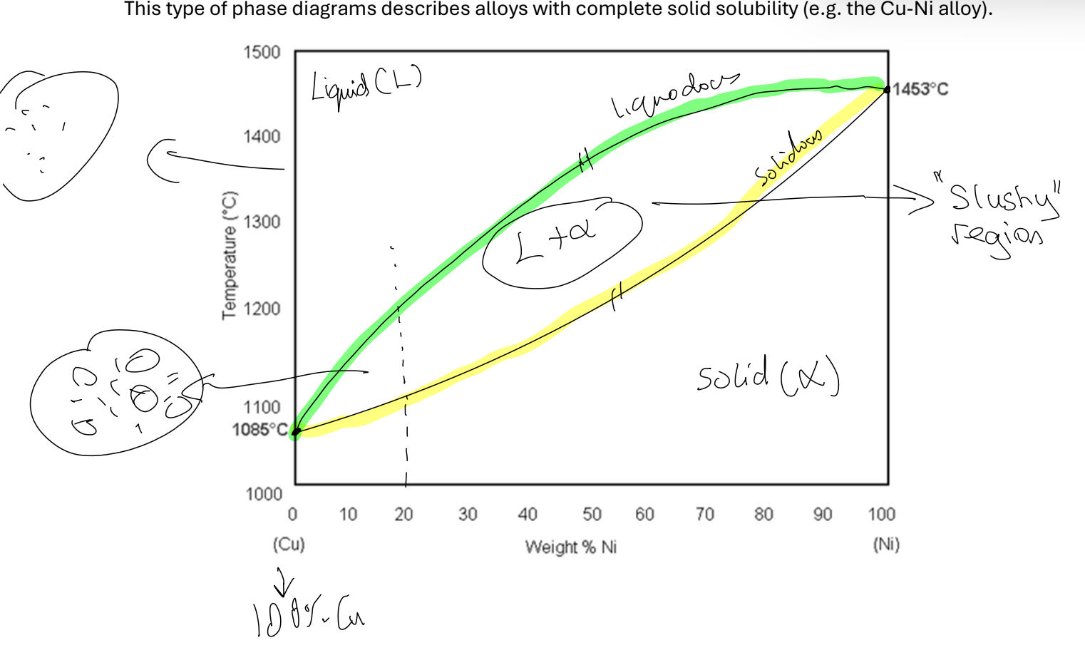
diff element atoms are substituting some atoms in parent crystal lattice. Can have limited (Al-Cu) OR unlimited (Cu-Ni) solubility
Binary Isomorphous alloys
consists only 2 diff elements. W/ complete/unlimited solubility only 2 phases formed:
Solid phase α
Liquid phase
Phase diagrams can tell us:
- What phases exist in equilibrium
How many phases
How much of each phase
Composition of each phas
Lever Rule
Answers how much of each phase? at certain comp
Plot point at chosen temp and overall composition
Draw tie-line through point to phase boundaries
Find % of lengths of tie line on either side.
% phase in material = % length OPPOSITE side of point
To answer composition of each phase:
read off where tie-line intersects phase change line. Intersection tells composition
Binary eutectic alloys
when it has limited solubility
solid phase α - 1 in 2
solid phase β - 2 in 1
a liquid phase
when temp changes solubility limit changes.
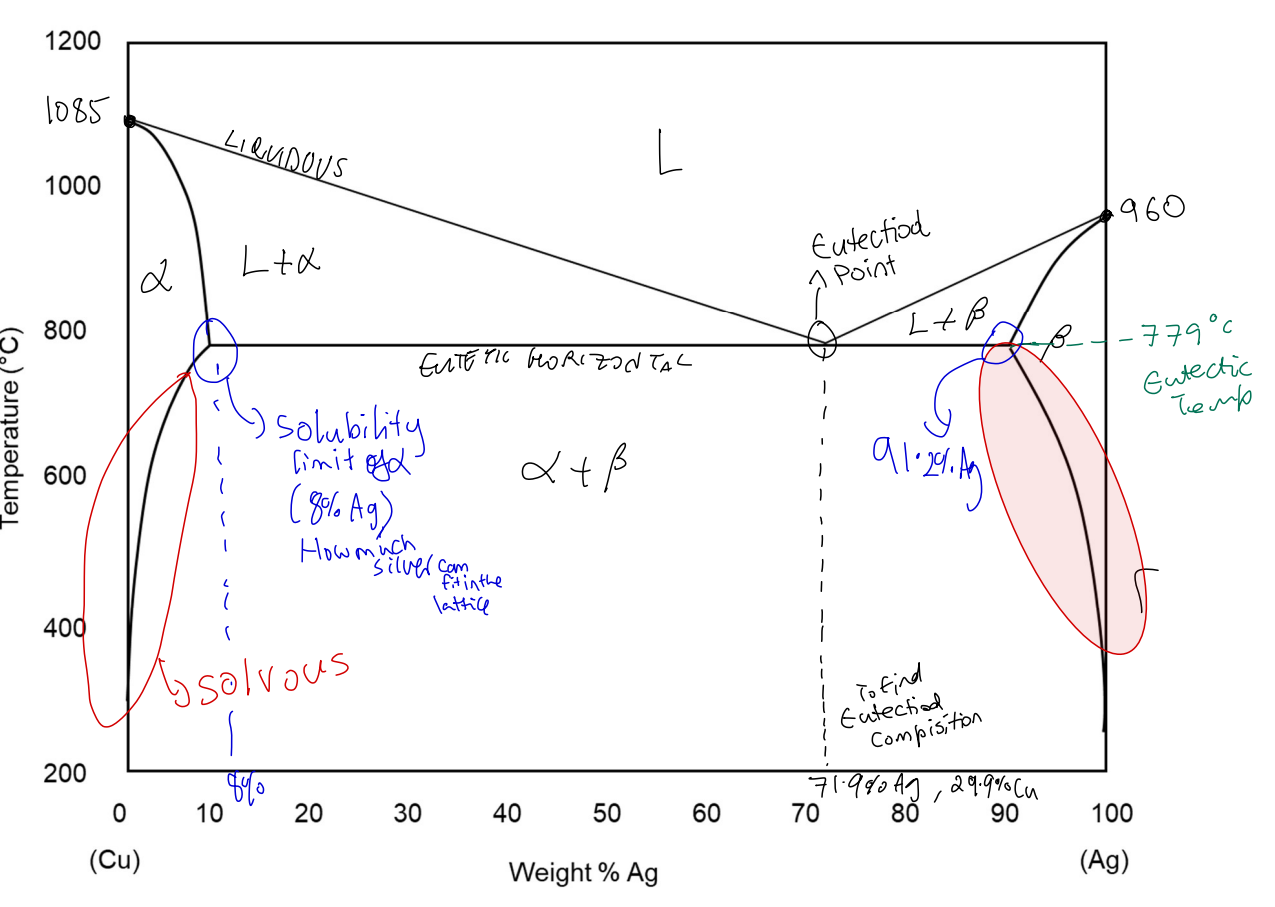
Eutectic reaction
At eutectic point:
alloy melts at single temp
single liquid phase turns into 2 solid phases
L_eutectic →add cool/heat→ alpha + beta
This reaction produces layered 2-solid phase structure called eutectic solid
NOT A PHASE, combination of 2 phases.
HYPOEUTECTIC → less than eutectic composition
HYPEREUTECTIC → more than eutectic composition
PROEUTECTIC → solid phase before eutectic solid
how much eutectic solid would there be in the final microstructure when a certain alloy is cooled down slowly from its liquid phase?
CANNOT apply lever rule. look just above eutectic temp
Steel wt% C
Low carbon steel: up to 0.25%C
Med carbon steel: 0.3-0.5%C
High carbon steel: 0.55-0.95%C
Cast irons: up to 4%C
Phases in Fe-C system
Gamma iron (γ) or austenite
FCC iron parent lattice accommodate up to 2.1wt%C
Exists above 723
Ductile (many slip systems) non magnetic
Alpha iron (α) or Ferrite
BCC iron parent lattice up to 0.02%C
between RT-910
Ductile (several slip systems) magnetic
Cementite (Fe3C) or iron carbide
not solid solution, compound of fixed composition (6.67%C)
Can be thought of as ceramic
orthorhombic strcture a ≠ b ≠ c
no slip systems very brittle and hard
Fe-C phase diagram
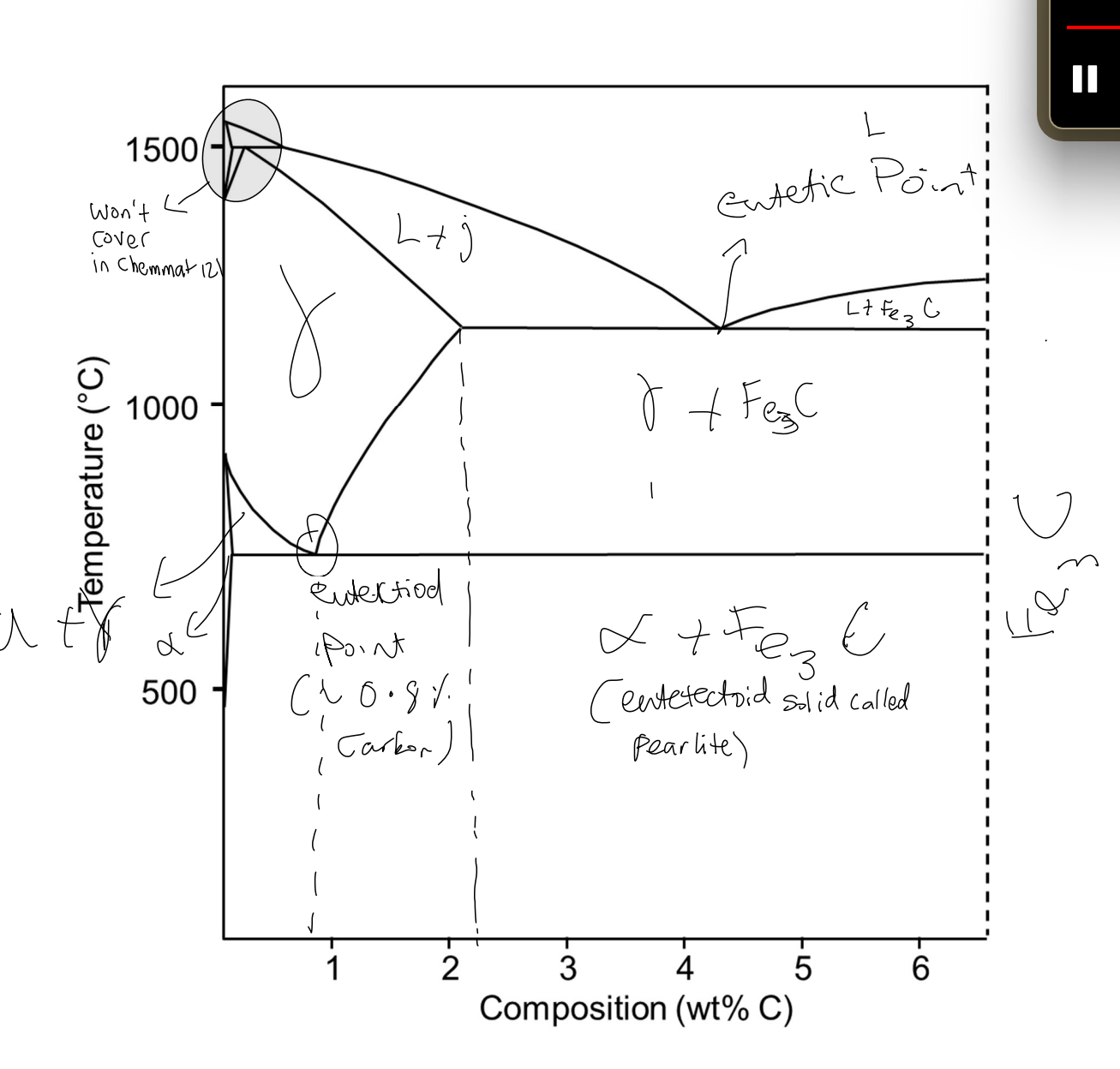
Eutectoid reaction
γ(eutectoid) → cool/heat → alpha + Fe3C
Takes place 0.8 wt%C and 723
Produces eutectoid solid called PEARLITE, only formed slowly cooling eutectoid reaction
Steel w/
LESS eutectoid composition → hypoeutectoid & proeutectoid alpha + pearlite
MORE eutectoid composition → hypereutectoid & proeutecoid Fe3C + pearlite
first solid phase before pearlite is called proeutectoid solid.
Strengthening mechanisms for pure metals
Work hardening
any plastic def. increases strength of crystalline material
Grain Boundary Strengthening
smaller grains → stronger. To get small grains → do lots of CW → anneal
To get big grains → let grain growth happen
Rule of thumb strengthening mechanisms in metals
If dislocations can move easily → weak and ductile
OR
to increase strength stop dislocation movement.
Solid solution strengthening
WITH ALLOYS can be substitutional or interstitial. atoms of diff elements have diff sizes.
both big and small solute atoms hinder dislocation movement as they have more distance to travel.
w/ complete solid solubility (e.g. Cu-Ni)
describe graphs
Multiphase stengthening
boundaries inhibit dislocation movement in crystal lattice includes phase boundaries, grain boundaries etc.
looking at phase diagram → max num boundaries → max yield stress → increase % eutectic solid.
alpha phase (solid solution of 1 in 2):
FCC - lots of slip systems
weak and ductile
Theta (compound e.g. CuAl2):
BCT (aab) - no slip systems
strong and brittle
Multiphase strengthening microstructures
when slowly cooled down from liquid phase:
L → L+alpha → alpha + theta:
proeutectic alpha and eutectic solid
low strength, high ductility
Straight through eutectic point:
100% eutectic solid
moderate strength, not very ductile
L → L + theta → theta:
proeutectic theta + eutectic solid
very strong VERY brittle BAD
due to brittle theta at grain boundries
Dispersion strengthening
aka age hardening/ precipitation hardening
having lots small hard ppts in ductile matrix (increases num boundaries). Two mechaisms:
discontinuity in slip systems → dislocation gets stopped by ppt
Distorts parent lattice → dislocations have further to travel
small ppts are more effective stopping dislocations than big ones (more finely dispersed).
Steps to get good microstructure for age hardening.
Solution heat treatment
heat alloy above solidus line to dissolve all Cu atoms.
Quenching
rapid cooling to room temp, doesn’t allow for diffusion. get supersaturated alpha phase (metastable)
Ageing
heat below solidus, allow for diffusion. get theta ppt within alpha matrix.
effects of time and temp on 3rd step of age hardening
Since its diffusion based it depends on time and temp.
If they aged at HIGHER temp, SHORTER aging time. This means less time to reach max strength so the max strength will be lower.
Overaging (leaving for too long, past peak) causes big incoherent theta ppt.
Requirements for alloy to be age hardened
phase diagram must show decreasing solid solubility with decreasing temp i.e. must be able to quench from single solid phase to a 2-solid phase region
parent matrix → soft & ductile. strengthening ppt → hard and brittle & finely dispersed through softer parent phase/ Soft ppt will break when hit by dislcoation.
ppt should be coherent w/ parent matrix & distort it to create srain fields. makes dislocation movement diffcult
alloy should be able to survive quenching process. Sudden temp change causes thermal shock & shape distortion & cracks.
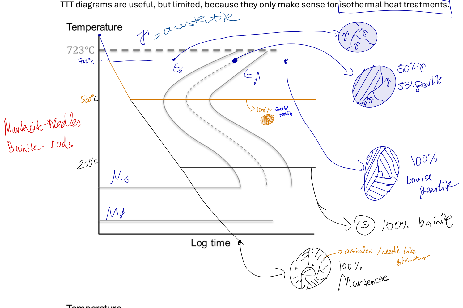
Strengthing mechanisms - pearlite
layered structure, effective multiphase strengthening. austenite → cool + heat → alpha + Fe3C. formed when austenite at eutectoid comp cooled slowly under eutectoid temp. formation depends on solid state diffusion of C atoms. @ high temps ~700 - COURSE PERALITE @ low temps ~500 - FINE PERALITE
Martensite
austenite quenched instead of slow cooled, ssd does not occur, pearlite not formed, instead martensite.
Has BCT structure formed through shear/displacive transformation, diffusion not required. made from 2 austenite unit cells
a supersatureated solid solution of C & Fe | @ RT alpha has 0% C. BCT → no slip system → hard & brittle
a metastable structure | not on Fe-C phase diagram, transform into alpha + Fe3C is solid state diffusion allowed
increasing hardness with C content of steel | solid solution strengthening, more carbon → more lattice distortion
TTT curves
Time-Temp-Tranformation
only make sense for isothermic heat treatment (constant temp).
earliest eutectoid comp at “nose” of curve.
Tempered Martensite
temper martensite to get alpha + Fe3C (NOT PEARLITE). tempering → reheat then cool slowly, get Fe3C ppt in alpha matrix. Tempered martensite optimium strength w/ suffcient ductility & toughness.
Tempering effects size & dispersion of Fe3C ppt in ferrite matrix.
IDEAL: fine ppt
if ppt TOO BIG less strength, caused by increases temp & time.
What happens if quenching of steel is not done properly?
causes structural variation problems. usually:
martensite closest to edge → then banite → then fine pearlite → then course pearlite
Can be fixed by adding other elements than slow carbon diffusion e.g. 1wt% Mn
Spheroidised steel
weakening mechanism, slow cooled high C steels have lots hard & brittle Fe3C phases. They wear tools quickly. Can be made softer by spherodising, transforming Fe3C layers into spheres.
heat to ~700 then hold for several hours
Thermodynamic driving force:
reduction in Fe3C surface area (or energy)
Influence of carbon content on hardness/strength of steel
Quenched steel (martensite):
- more c → more distortion
Quenched and tempered:
more C → more ppt
Slow-cooled steel (pearlite):
more c → more strength
Polymerisation
double bonds in monomer between 2 cs open up and are replaced by single covalent bond, allows c atom to bond to another one. This is repeated and forms a polymer chain.
Degree of polymerisation (DP)
(avg molecular weight of chains in polymer)/(molecular weight of repeating unit)
aka avg num repeating unis/monomers in each chain.
since polymerisation produces chains of varying length, molecular weight is always avg.
Shape of Molecule
not straight → zig zag config. bcuz carbon tetravalent (forms tetrahedral shape)> 109.5 degree angle between all c atoms. C atoms can occupy any pos rotating around bonds.
rotational movement + thermal vibrations = diff shapes and configs.
Micro chain structure: blocks
Bulk chainstructure: like spagitte
Effect of DP on polymer strength
degree of tangling increases w/ chain length (increases DP). as weaker 2ndary bonds between chains.
Shorter chains (less DP)
less 2nd bonds, easy to break & chains to slide = less strength
Long Chains (More DP)
more 2nd bonds, difficult to break & hard chain slides = more strength. also more chain tangling increases strength
At max strength due to 2nd bonding + tangling
failure occurs by breaking of covalent bonds w/in chain
Polyethylene (PE)
4 small H atoms
LDPE
recycling num 4, grocery bags, cling film, bubble wrap.
Branches of PE grafted onto main chain, prevents close packing, less crystalline regions, 2nd bonding, strength
HDPE
recycling num 2, milk bottles, cleaning product bottles.
Linear chain → segments line up easily
high crystalline, 2nd bonding, and strength
Polyvinylchloride (PVC)
small Cl atom + 3 H atoms. recycling num 3
Unplasticised (Hard)
spouting, plumbing products
Plasticised (Flexible)
hoses, cleaning product bottles
Polytetrafluoroethylene (PTFE)
“Teflon” 4x small F atoms, white/opaque in pure form
chemically inert, low friction, high melting point
Flourine small reactive atom, forms symmetrical chains, high: crystallinity, 2nd bonding, strength, density, melting point.
Strong C-F bonds: high chemical inertness, slipperiness.
Doesn’t melt normally
Polypropylene (PP)
Large CH3 side groups 3x small H atoms
transparent in pure form, recycling num 5
rope, bottle caps, garden furniture, takeaway containers.
Can have atatic or Isometric forms. Isotactic forms stronger.
Polystyrene (PS)
Very large side group transparent in pure form, recycling num 6
Expanded PS
protective packaging, takeway containers
Conventional PS
disposable cutlery, polymer “Glassware”
Polymethylmethacrylate (PMMA)
Very large side group, AND CH3 side group
Perspex or Acrylic
aircraft windscreens, safety glasses
Completely amorphous. Large side groups prevent close packing.
Polymer chain structures
Homopolymers
same monomer repeating
Co-polymer
2 or more chemically diff monomers
Alternating; block; random; graft (side group B attached to A)
Linear polymers
monomers joined end-end, no branching
long flexible chains, pack close together, HDPE
Branched polymers
main polymer chain w/ connected side branches, branching reduces chain packing = low density LDPE
Cross-linked polymers
linear chains joined covalently bonded chain segments from 3-d structure
Cross links prevent chains move relative to each other → stiff hard and strong
Thermoplastic polymers (thermoplastics)
Linear branched polymers w/ weak 2nd bonds
soften with increasing temp
heat → increased thermal vibrations → decreased 2nd bonds → allows relative movement under stress
cooling → decreases thermal vibrations → increases 2nd bonds → original properties return
process reversible, polymer can be reheated & reshaped, good for recycling
Thermosetting polymers (Thermosets)
crosslinked polymers
strong covalent bonds prevent flow relative to each other (no chain sliding)
harder & stronger than thermoplastics
can’t be melted or recycled
at high temp burn, degrade, and char