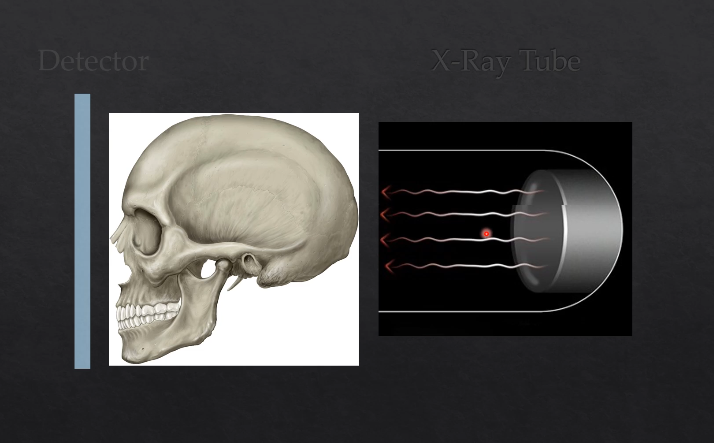
What is an Xray image?
1/43
There's no tags or description
Looks like no tags are added yet.
Name | Mastery | Learn | Test | Matching | Spaced |
|---|
No study sessions yet.
44 Terms
the more X rays that hit the detector….
the darker the image is - the more RADIOLUCENT the image is
the fewer Xrays that hit the detector …
the lighter the image is - the more RADIOPAQUE the image is
denser/thicker objects will….
denser or thicker objects will absorb more Xrays - and therefore less Xrays will hit the detector and that area will appear whiter/more radiopaque
less dense/thinner objects will…
less dense/thinner objects will absorb less Xrays, therefore more Xrays will hit the detctor in that area and the image will appear darker or more radiolucent in that area
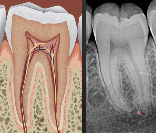
what can we determine from this radiograph?
the densest part of the tooth - enamel - appears most radiopaque as it absorbs/stops the most Xrays
dentine is more radiolucent
pulp is most radiolucent as its not calcified
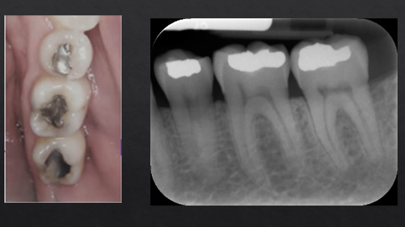
silver/amalgam restorations absorb the most Xrays - most radiopaque
what are the two exposure factors?
changing the exposure time and changing the Kv
how does changing the exposure time affect the image?
too high - overexposed, dark image
too low - underexposed, light image
how does changing the KV affect the image?
changes the intensity/how penetrating of the Xray beam…
reducing KV, increases contrast but also the dose
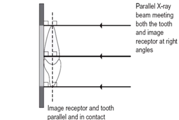
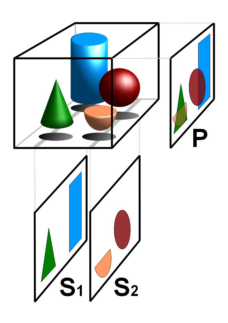
image geometry
the aim is to achieve images that are as geometrically accurate as possible
with minimal distortion
it’s hard to get a perfectly geometrically accurate image - but we need to use techniques that minimizes any geometric distortion
we want the object that we are imaging to be as close to the detector as possible and WHAT ELSE?
and as parallel to the detector as possible
this is quite difficult due to the patient’s anatomy #
we have developed techniques to try and make the person’s anatomy as parallel as possible to minimize distortion
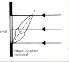
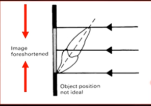
object position not ideal
image foreshortened
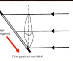
film position not ideal
image elongated
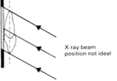
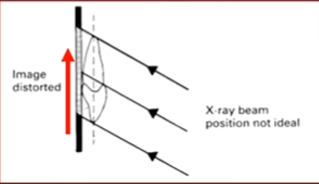
Xray position not ideal
image distorted
distance is important when managing distortion…
Xray tube, object, focal spot positioning is all important
affects magnification and image distortion
focal spot - which is the actual source of the Xrays - the further that spot is from the actual detector - then the LESS distortion there will be
the CLOSER the Xray source is from the detector - the greater the amount of distortion there will be

why is it that when the X ray beam is farther from the detector the less distortion there will be?
the X ray beam is DIVERGENT
when the Xray beam arrives from the focal spot at the anode, it then diverges
the further you are from the X ray source, the more divergent it will be
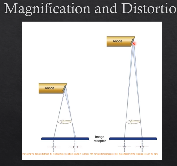
the farther the OBJECT is from the detector also affects the distortion- how so?
the further the object is from the detector - the more MAGNIFIED and DISTORTED that image will look
this is again, due to the fact that the Xray beam is divergent
the CLOSER the object is to the detector, the less magnified and distorted the image will be - more geometrically accurate
overall, how can you get an image with the least amount of distortion without too much magnification….
increasing the focal spot to image-receptor distance
decreasing the object to image receptor distance ORD

what are the 3 different images we can take? 3
intra-oral
extraoral
3D imaging
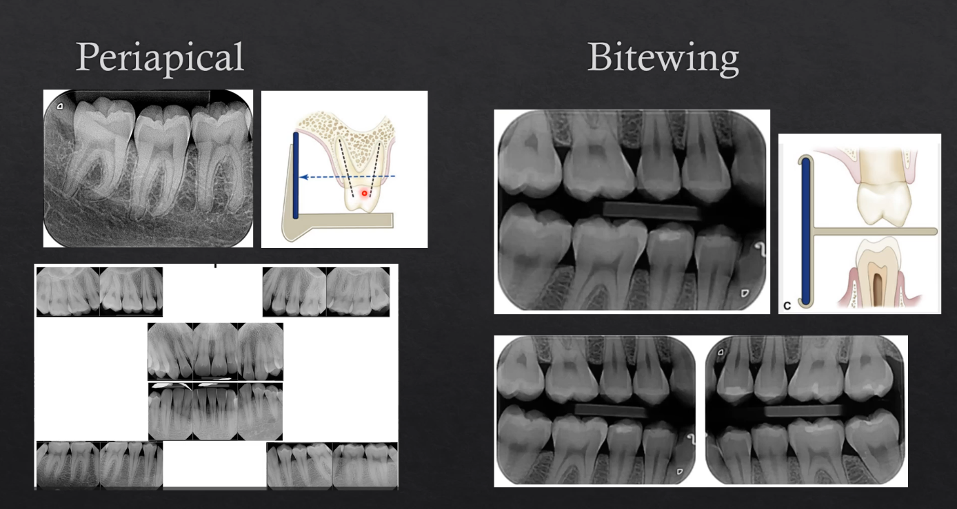
intraoral X ray example
periapical
bitewing
occlusal radiograph
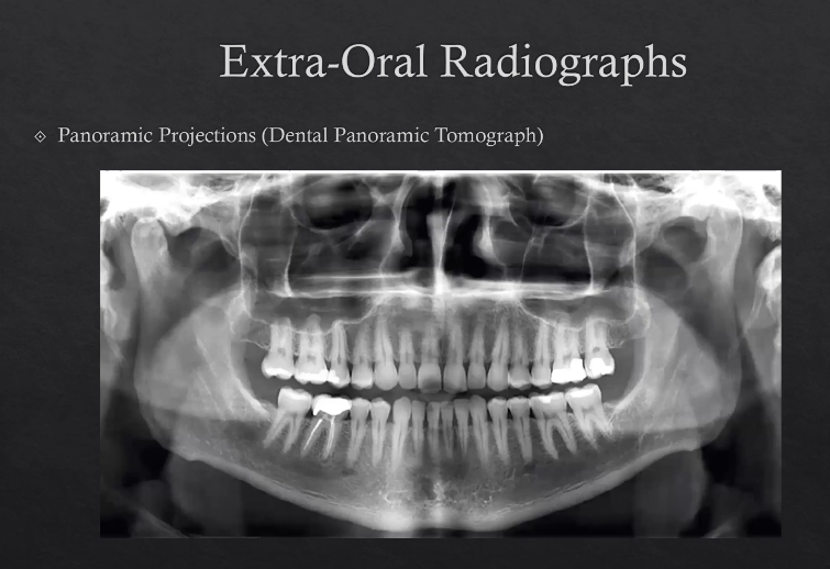
extra-oral radiograph example
planar projections (PA posterior/anterior mandible, lateral cephalogram) - hitting the detector at 90 degrees
panoramic projections - dental panoramic tomographs
3D imaging radiograph examples
cone beam CT
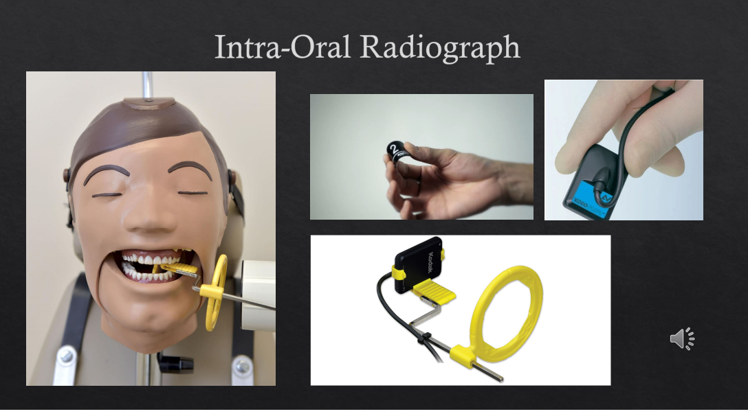
intraoral radiographs
most commonly taken radiograph in dental practices
utilizes small films and can be direct digital systems or can be phosphor plates or even digital films
film holder - gets X ray beams to be as perpendicular as possible and the object to be as parallel as possible
periapical vs bitewing radiographs
periapical is when the film is positioned such that the entire tooth is imaged - the crown to the apex of the roots and ideally3 or 4 mm of bone below the apex of the tooth - can be of a single part of the jaw or multiple in different images - takes an image of 3 or 4 teeth at a time
bitewings are also intraoral but the patient bites on a little peg the goes between the teeth → detector is imaging the bottom and the top teeth - all we see is the crown and the bone levels
extra-oral radiographs
planar projections (PA posterior/anterior mandible, lateral cephalogram) - hitting the detector at 90 degrees
panoramic projections - dental panoramic tomographs DPT
detector is OUTSIDE the patient’s mouth
planar projections
posterior/anterior mandible, lateral cephalogram
called posterior/anterior because the Xrays are coming from the posterior to the anterior, detector is touching the patient’s face and the Xrays are coming from behind
Xrays hit the detector at 90 degrees
lateral ceph - most commonly used in orthodontics - view patient’s soft tissues and their jaws - detecto9r is on the lateral side of the patient Xrays cross through the lateral surface of the patient
panoramic projections - DPT
technique is a little more specialized
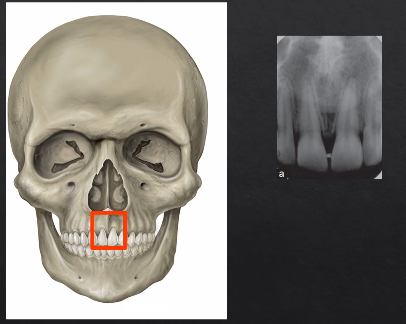
periapical radiograph, detector is inside a patient’s mouth
Xrays come in from the outside through the teeth and towards the detector on the inside of the mouth
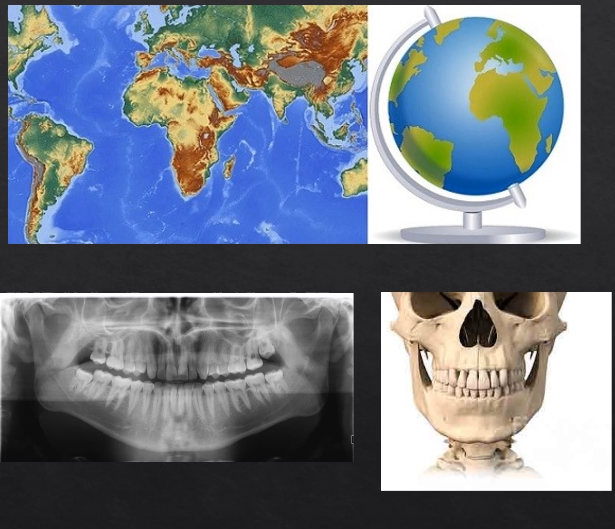
panoramic radiograph - DPT
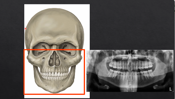
what happens if you pass the Xrays from directly behind the patient?
hits the detector on the outside, where their face is
image would form something like this - this is a PA → posterior anterior mandible is
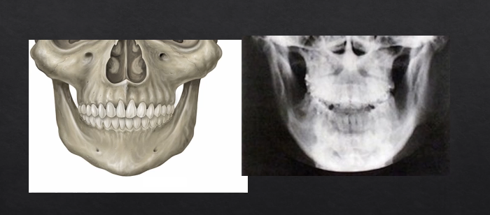
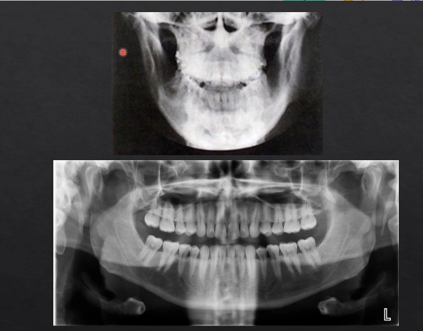
PA radiographs vs panoramic radiographs DPT
the panoramic radiograph looks different because the specialized technique
patient is positioned in the unit - bite their teeth together on a bite-peg
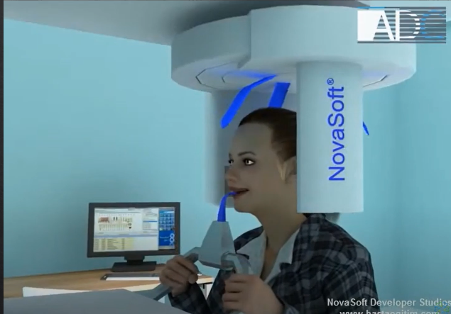
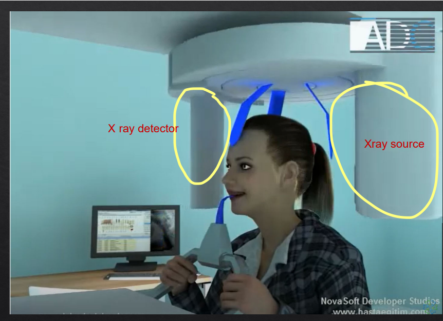
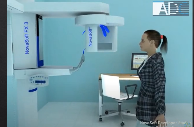
panoramic DPT cont’d
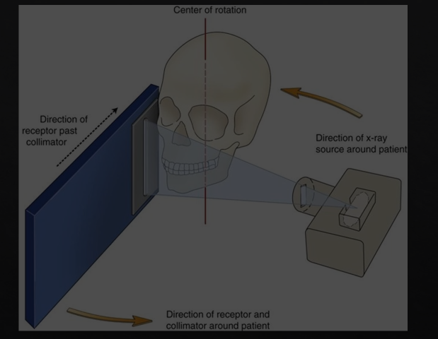
extraoral because the detector is outside of the patient’s mouth
both the source and the detector will rotate round the patient’s head by 180 degrees
taking X rays at different angles around the patient as it moves round the circumference
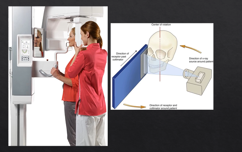
as the X rays are produced at the detector they are columnated to an envelope shaped beam - see image where the X rays are produced
then they pass through the patient and are collimated again at the detector at an enveloped shaped area
with a single projection taken at one point of rotation - there is an exposed slit of the detector
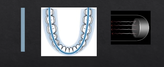
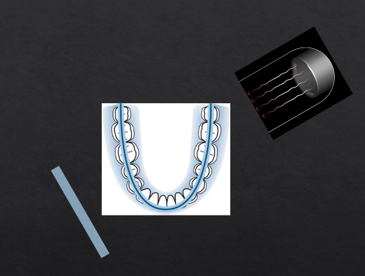
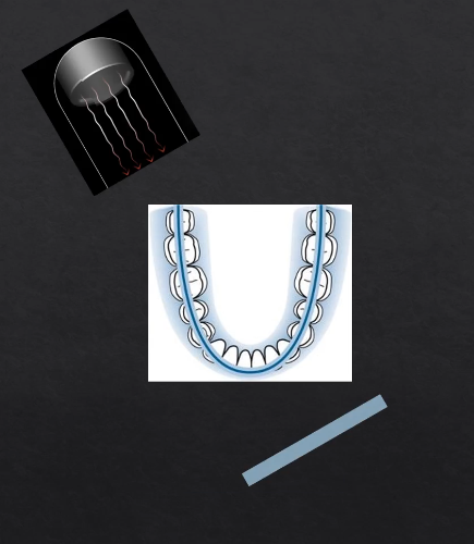
with each degree of rotation we are only exposing a a letterbox slit of the detector
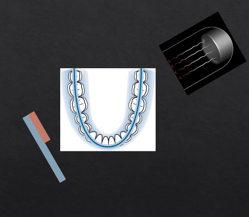
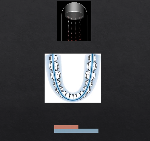
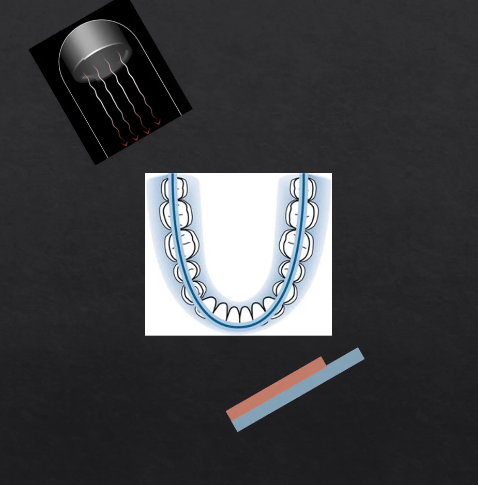
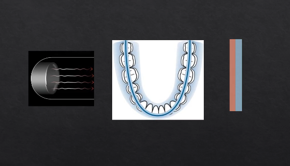
as we move points of rotation , more and more of the detector gets exposed → at 180 degrees we fully expose the whole length of the detector
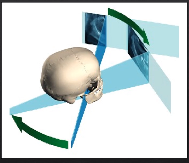
each bit of the detector is being exposed but separately - like a printer - or like a panoramic photo → but this creates some geometric distortion
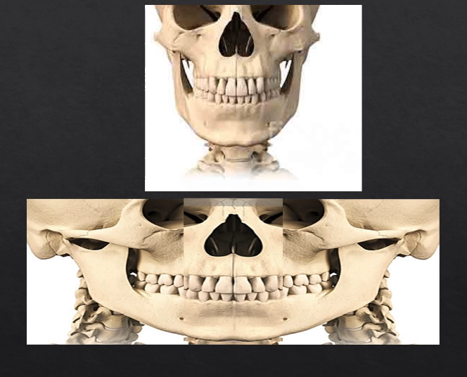
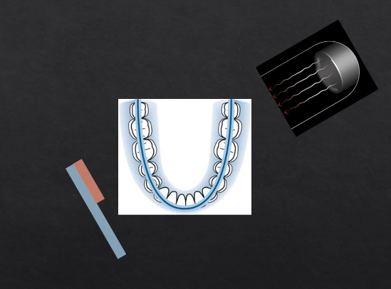
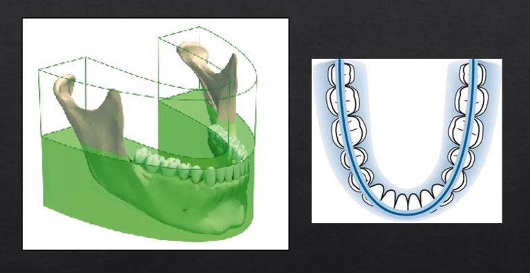
why is it called a dental PANORAMIC TOMOGRAPH
panoramic - small parts/images stitched together to form the full image
tomograph - refers to the part where we’re taking a slice through the patient’s anatomy
horseshoe shaped slice ??
anything within the green area is referred to as the focal troph - will be formed within the image
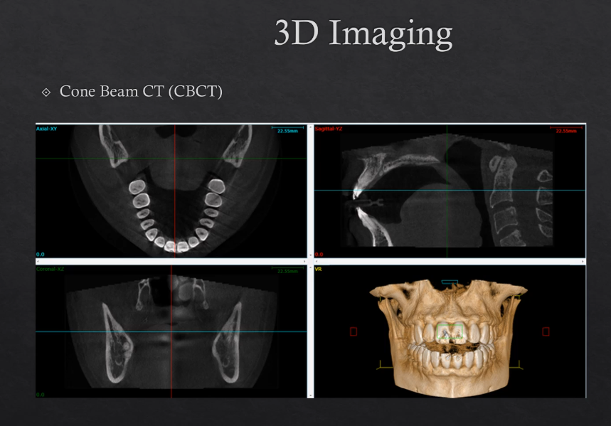
3D imaging
cone beam CT , CBCT
Uses more Xrays from different angles - this contributes to a higher dose
modern technique
can be used to make 3D models