Chapter 20: Exposure and Technique Errors
1/108
There's no tags or description
Looks like no tags are added yet.
Name | Mastery | Learn | Test | Matching | Spaced | Call with Kai |
|---|
No analytics yet
Send a link to your students to track their progress
109 Terms
Angulation
A term used to describe the alignment of the central ray of the x-ray beam in the horizontal and vertical planes
Horizontal Angulation
refers to the positioning of the PID in a horizontal, or side to side, plane
Vertical Angulation
Refers to the positioning of the PID in a vertical, or up and down plane.
Cone-Cut
Appears as a clear, unexposed area on a dental radiograph and may occur with a rectangular or round PID

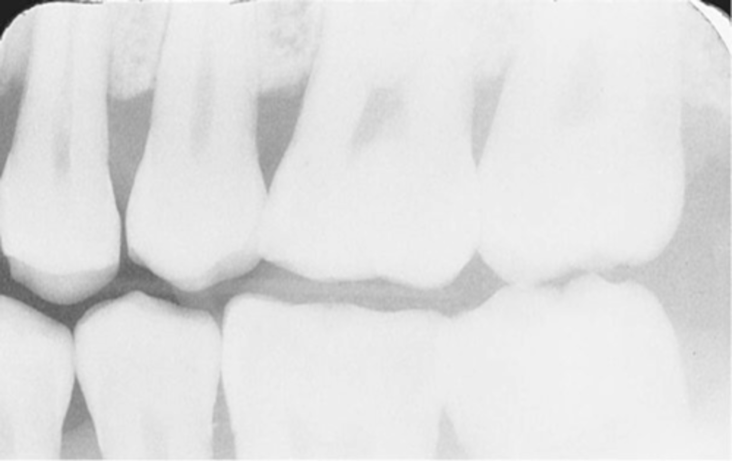
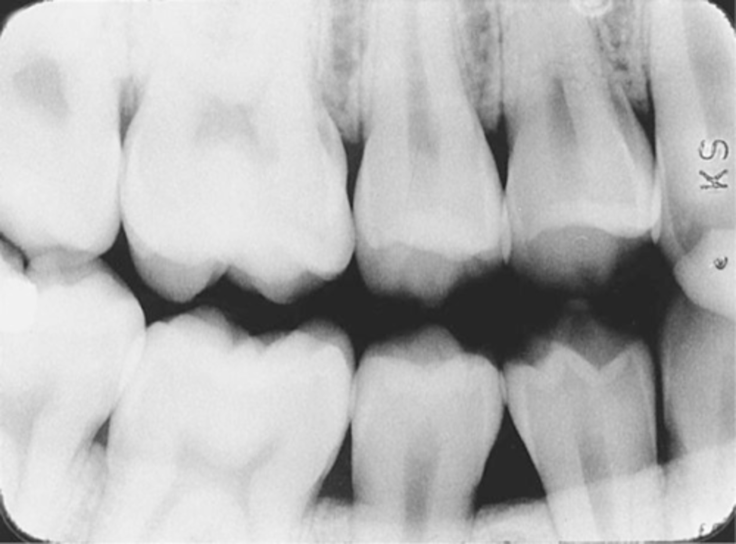
Overlapped Contacts
On a dental image, the area where the contact area of one tooth is superimposed over the contact area of an adjacent tooth
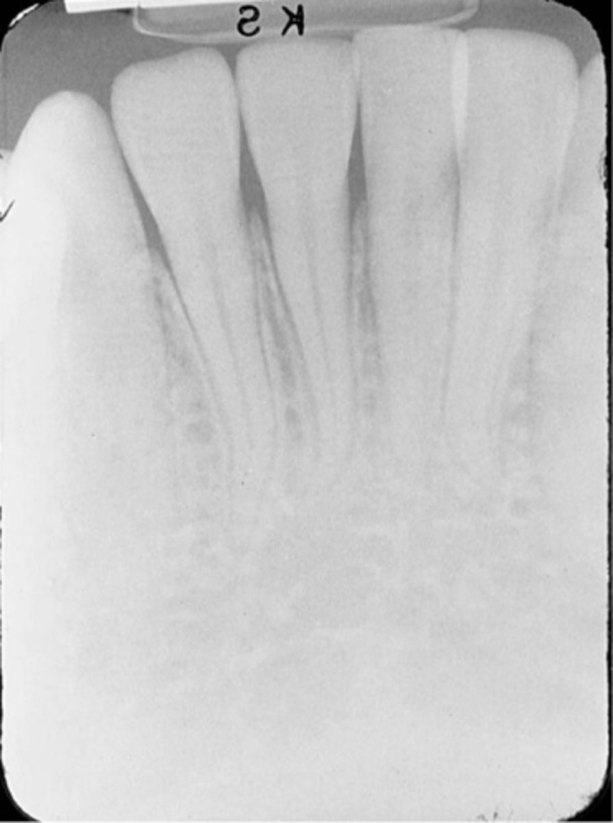
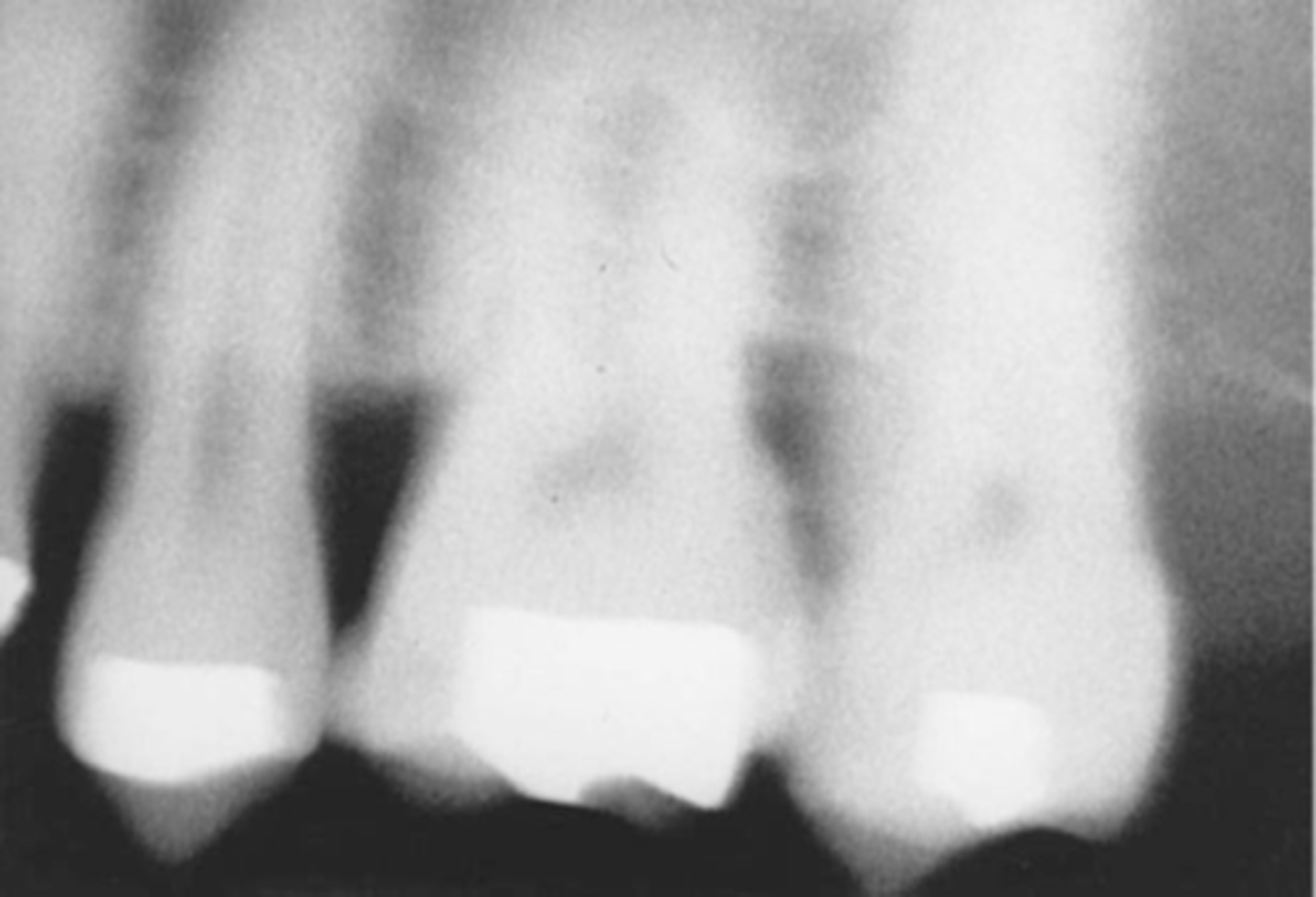
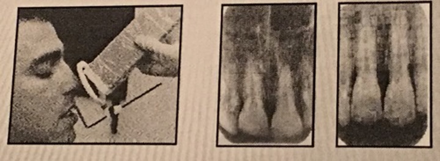
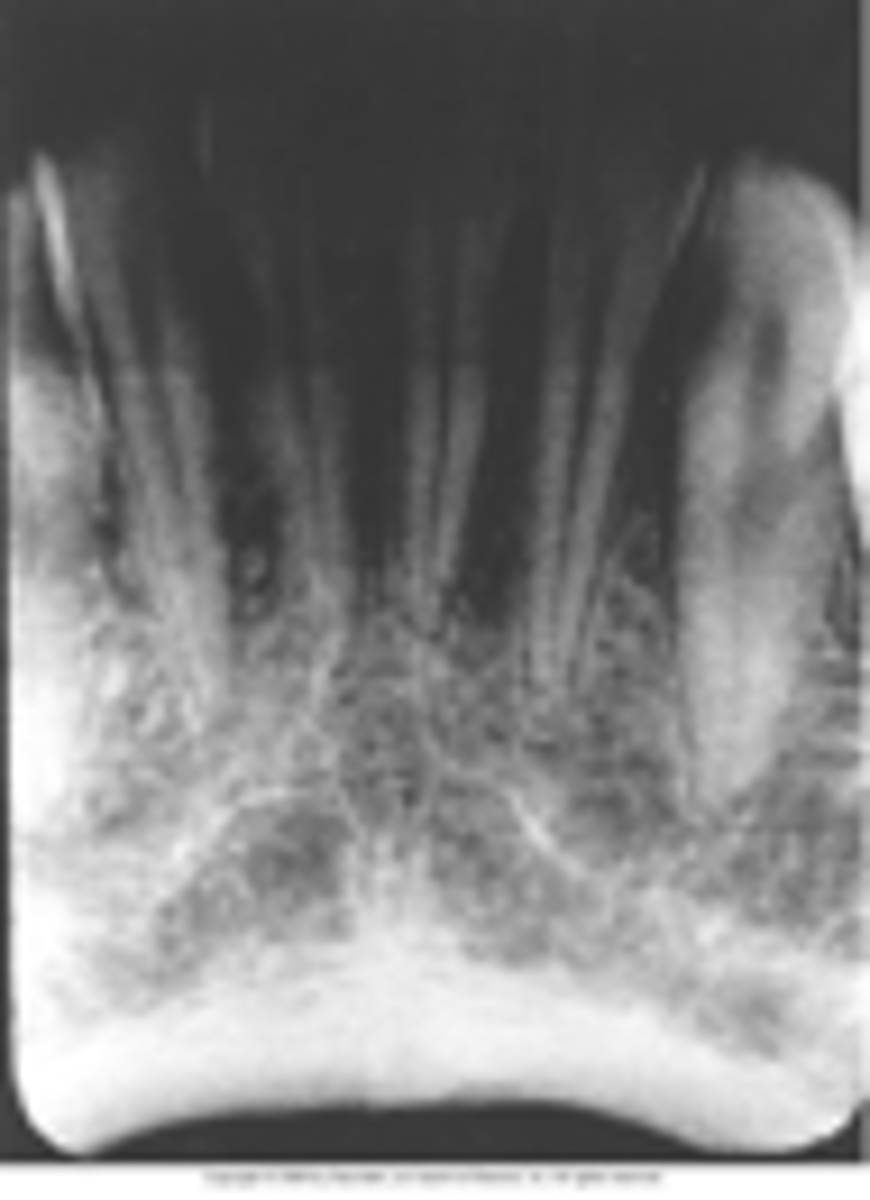
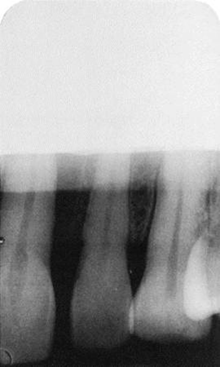
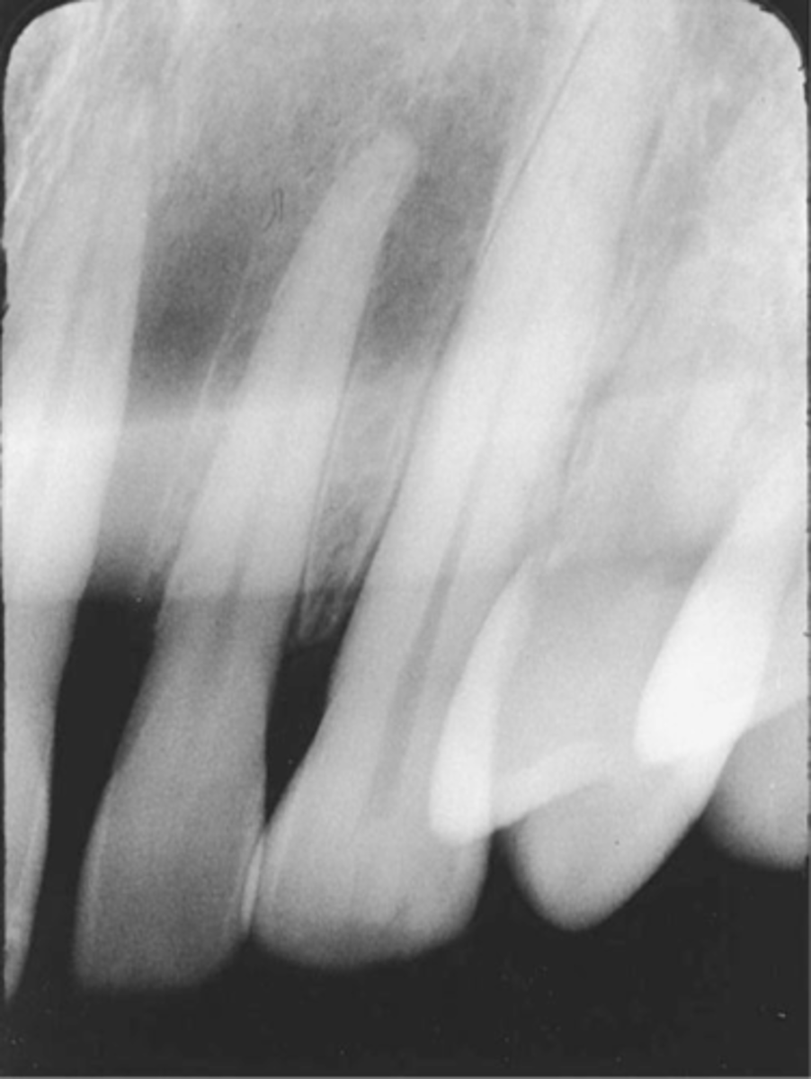
Elongated images
Vertical angulation was insufficient or too flat resulting in images that are longer than the actual teeth.
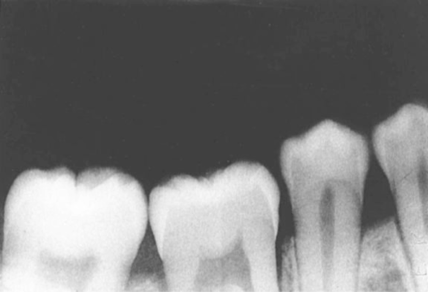
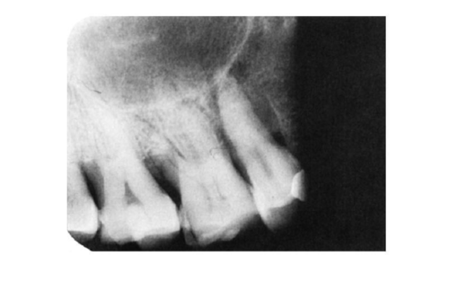
Foreshortened images
The vertical angulation was excessive, or too steep, and as a result images are shorter than the actual teeth

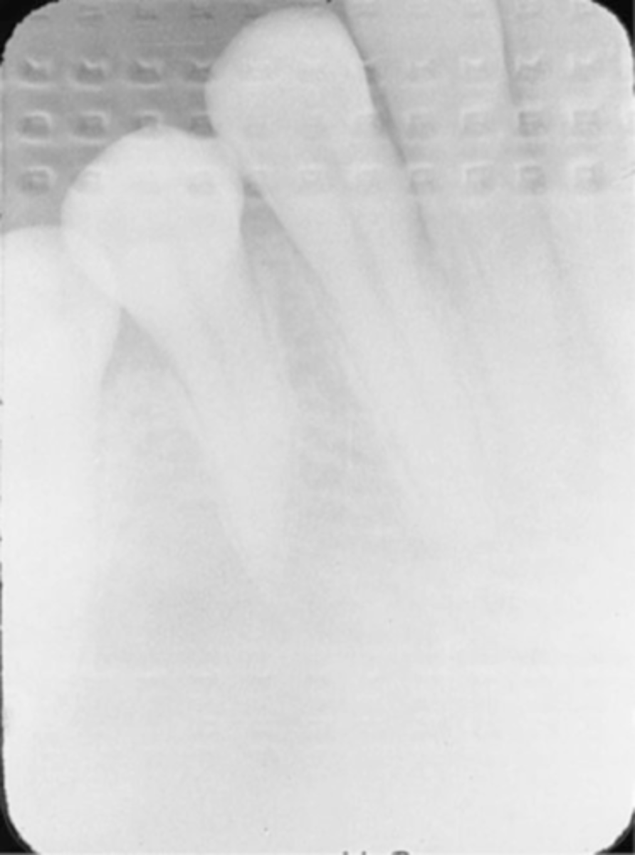
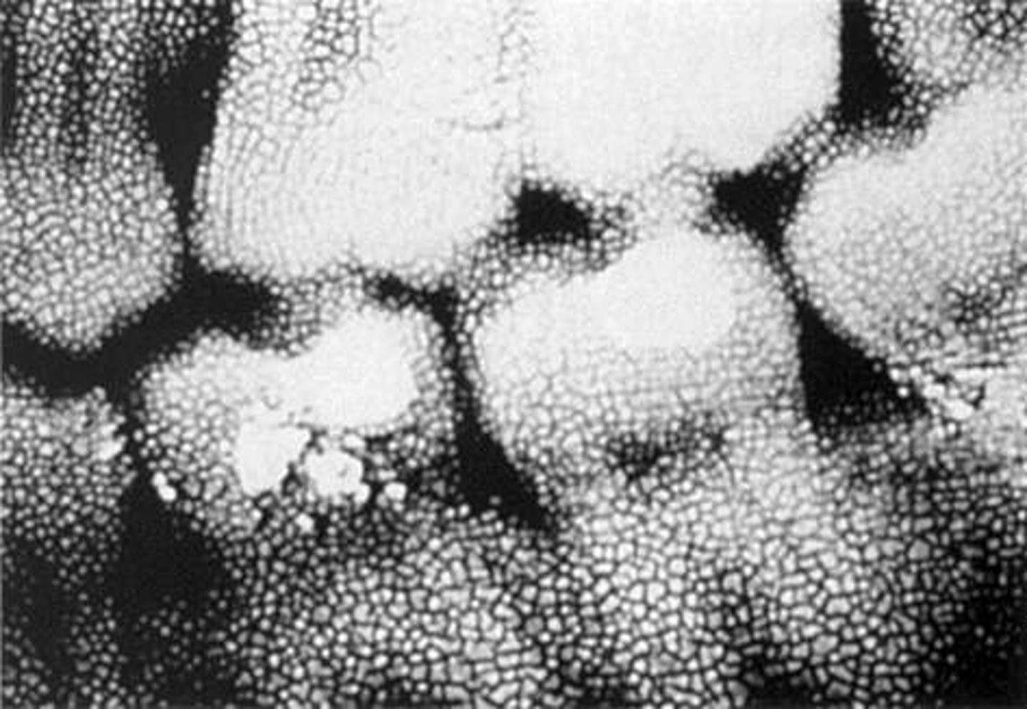
Herringbone pattern
Also known as tire track pattern and is representative of the actual pattern embossed on the lead foil

Phalangioma
Refers to the distal phalanx of the finger seen in the radiograph

Overexposed Receptor
Results from excessive exposure time, kVp, mA, or a combination of these factors

Underexposed Receptor
Results from inadequate exposure time, kVp, mA, or a combination of these factors

Receptor Exposure Errors
-Errors that result in nondiagnostic images that include unexposed, overexposed, and underexposed receptors, and film that is accidentally exposed to light.
-All these errors produce images that are too light or too dark
Exposure Problems-->Unexposed receptor
-Image appears clear
-Receptor was not exposed to x-radiation: Failure to turn on the machine or malfunction
-Make certain machine is on and listen for the audible exposure signal
Exposure Problems-->Film exposed to light
-Image appears black
-Film was accidentally exposed to white light
-Do not unwrap film in a room with white light, check darkroom for possible light leaks
Time and Exposure Factor Problems-->Overexposed Receptor
-Image appears dark
-Exposed to too much radiation, kVp, mA, or a combination of these
-To prevent check the exposure time, kVp, and mA
Time and Exposure Factor Problems-->Underexposed Receptor
-Image appears light
-Not exposed to enough radiation, resulting from kVp, mA, or a combination of these factors.
-To fix check exposure time, kVp, and mA settings on the machine before exposing; Increase exposure time, kVp, or mA
Periapical Technique Errors
-Errors that include problems with receptor placement, angulation, and beam alignment
Incorrect Receptor Placement-->Absence of Apical Structures
-No apices are seen on the image
-Receptor was not positioned in the patients mouth to cover the apical regions of teeth, resulting in no apical structures and an excessive margin of receptor edge.
-This error can occur with both paralleling technique and the bisecting technique
-To fix make certain that no more than 1/8th of an inch of the receptor edge extends beyond the incisal-occlusal surfaces.
Incorrect Receptor Placement-->Dropped Receptor Corner
-Occlusal plane appears tipped or tilted
-Edge of receptor was not placed parallel to the incisal/occlusal surfaces of teeth, resulting in the occlusal plane appearing tipped on the radiograph.
-If pt. is not instructed to close on the bite block to hold the receptor firmly against the tooth, a corner of the receptor may drop or slip.
-To prevent this make certain that the edge of the receptor is placed parallel to the incisal/occlusal surfaces as the pt. bites their teeth together.
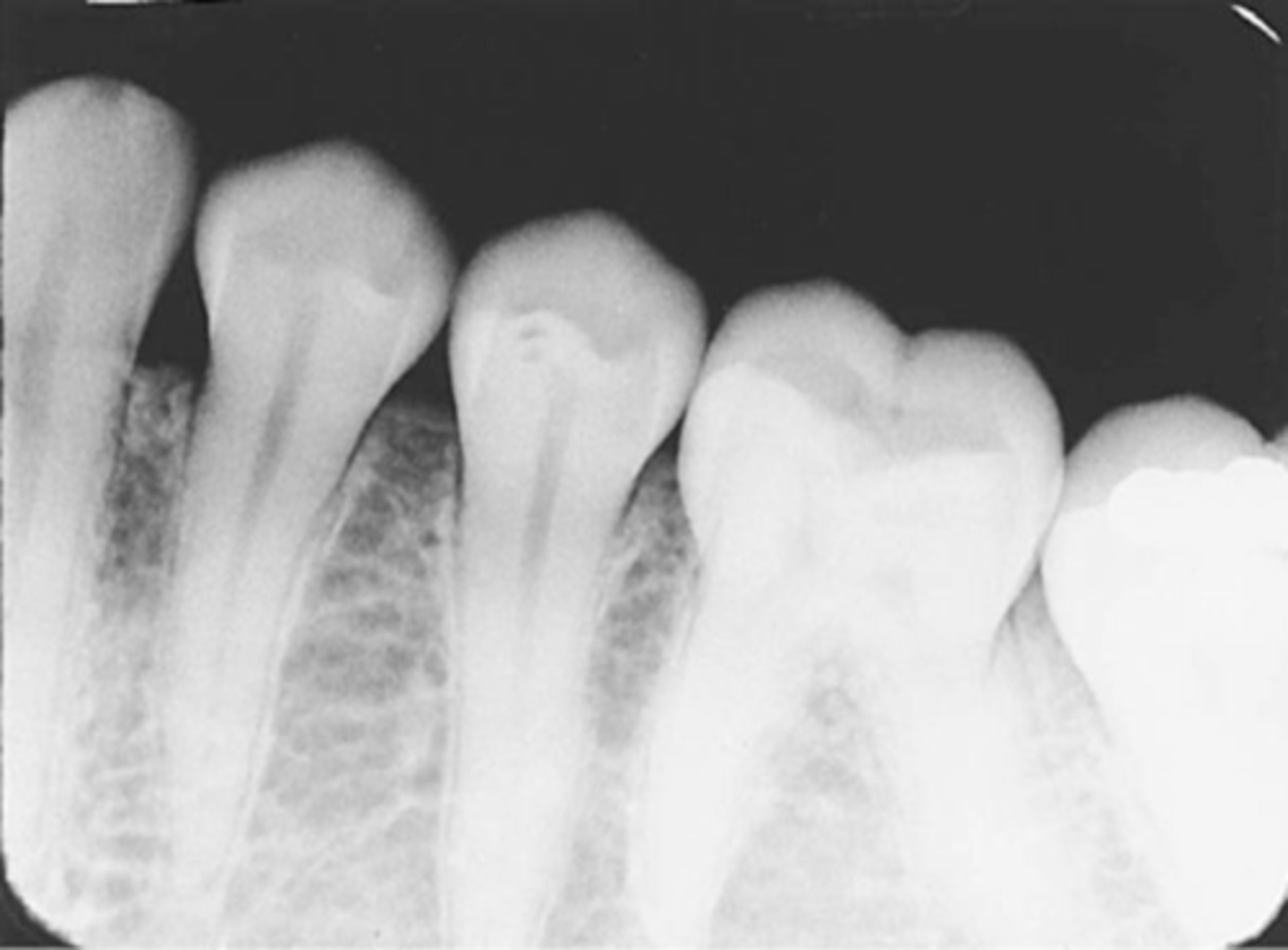
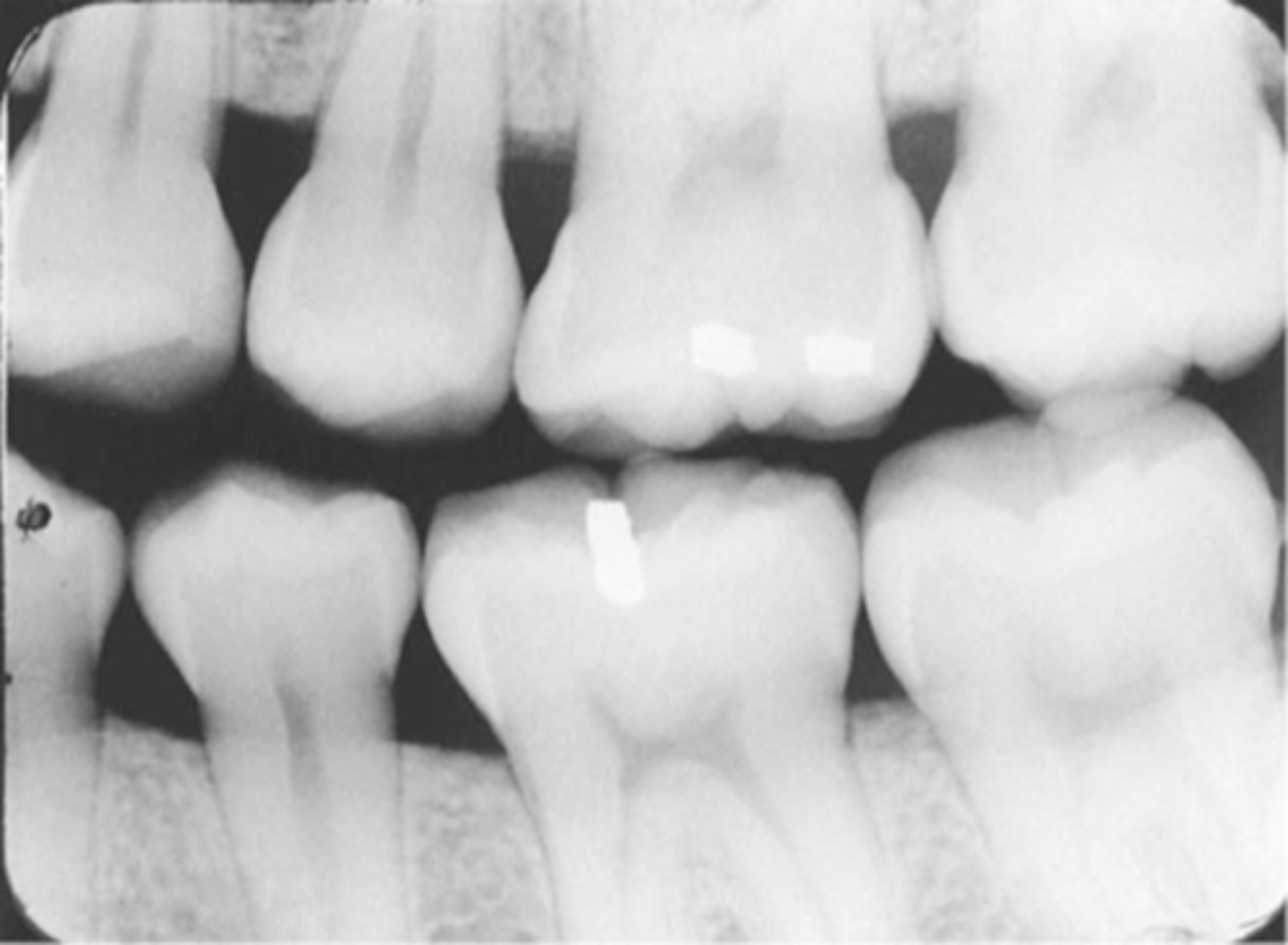
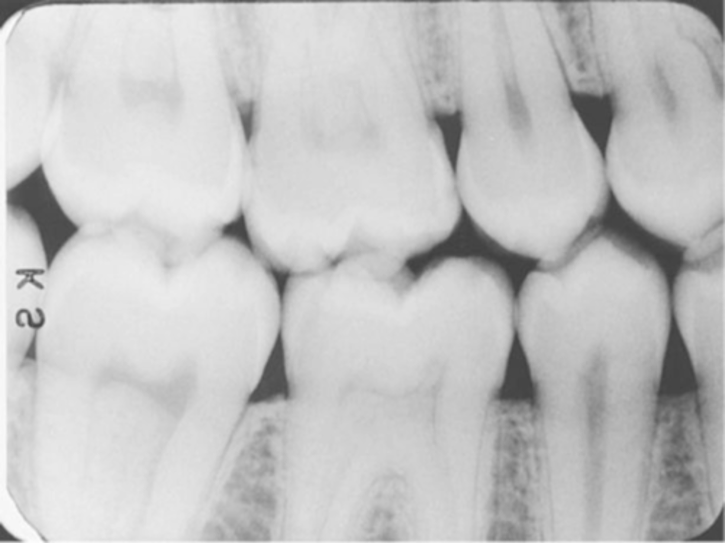
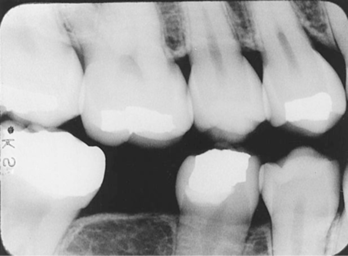
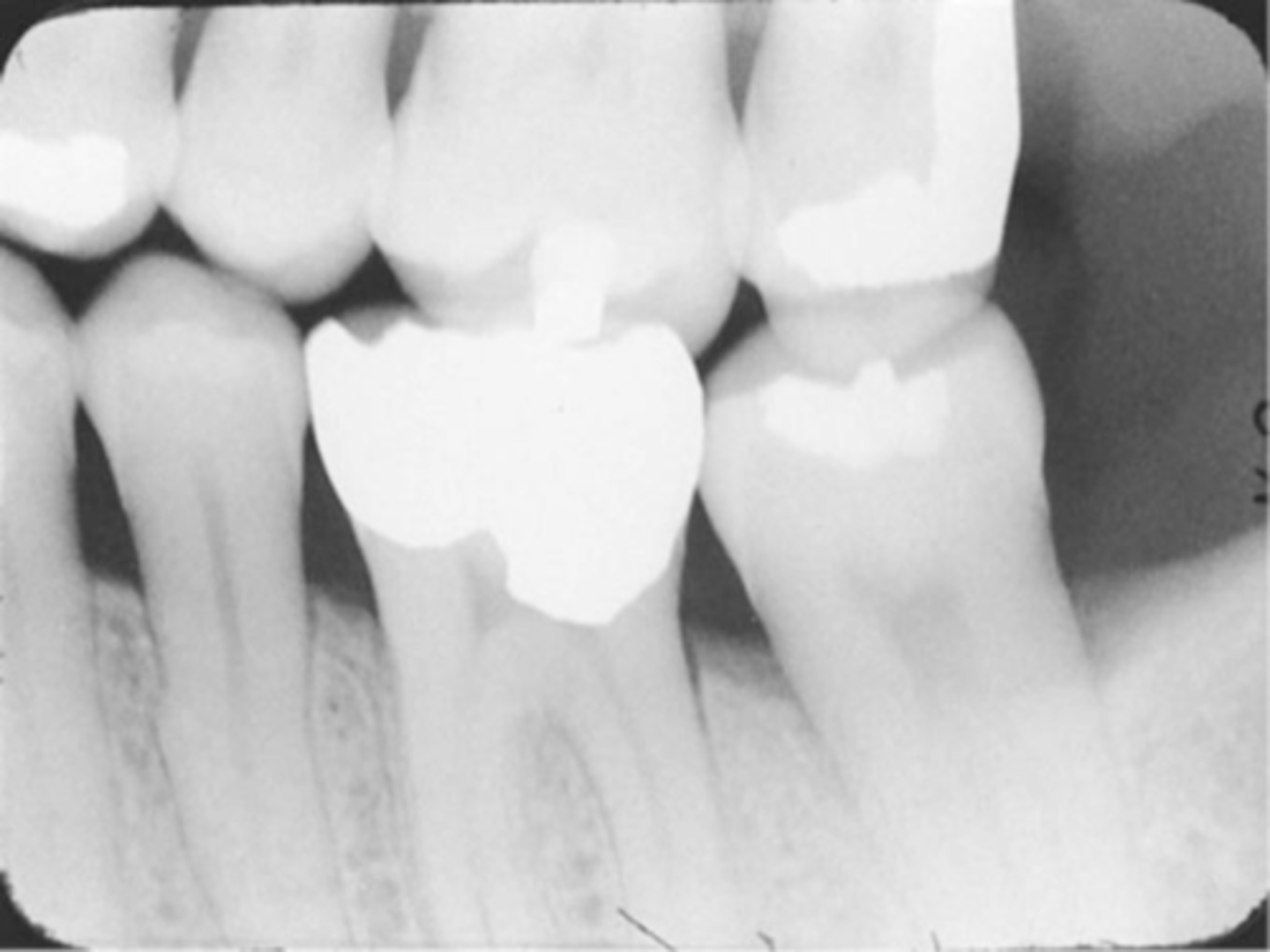
Incorrect Horizontal Angulation
-Overlapped contacts
-CR was not directed through the interproximal spaces, resulting in the proximal surfaces of adjacent teeth appear overlapped in the PA.
-Occurs in both paralleling and bisecting technique
-To prevent direct the x-ray beam through the interproximal regions

Incorrect Vertical Angulation
This can result in a radiographic image that is not the same length as the tooth; instead the image appears either longer or shorter or Elongated or Foreshortened and are nondiagnostic
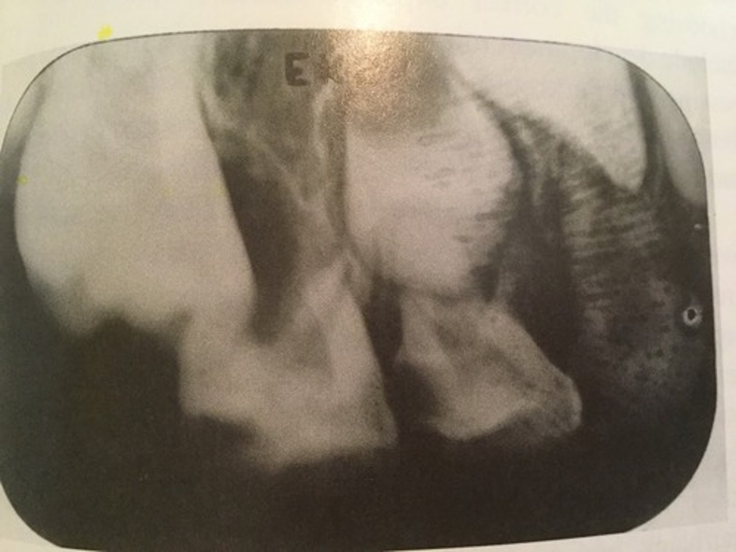
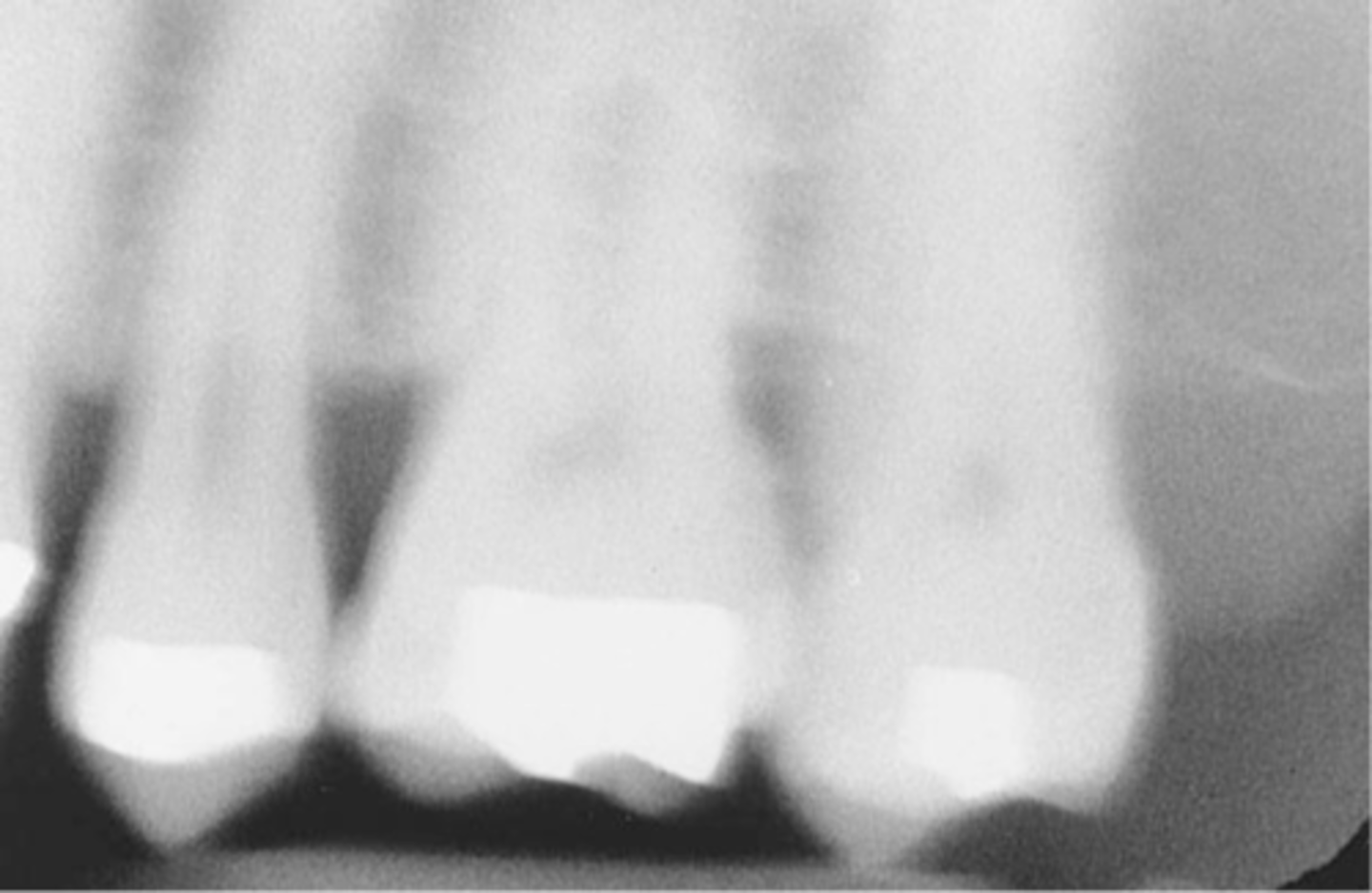
Incorrect Vertical Angulation-->Foreshortened Images
-Teeth appear short with blunted roots
-Vertical angulation was excessive, or too steep, resulting in images that are shorter than the actual teeth
-This occurs more often with the bisecting technique
-To prevent do not use excessive vertical angulation
Incorrect Vertical Angulation-->Elongated Images
-Teeth appear long and distorted
-Vertical angulation was insufficient or too flat, resulting in images that are longer then the actual teeth.
-Occurs more often with the bisecting technique
-To prevent use adequate vertical angulation

PID Alignment Problems
-PID is misaligned and the x-ray beam is not centered over the receptor, a partial image is seen
-PID or "cone" is said to "cut" the image.
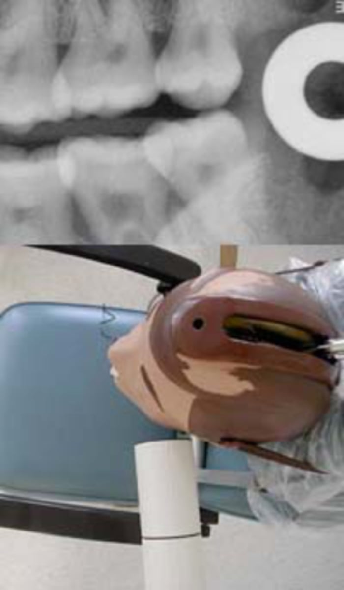
Cone-Cut with Beam Alignment Device
-A clear unexposed area is seen
-PID was not properly aligned with the PA beam alignment device and the beam did not expose the entire receptor, resulting in a clear unexposed area resembling the outline of the PID is seen
-To avoid make certain that the PID and the aiming ring are aligned
Cone-Cut without Beam Alignment Device
-A clear unexposed area is seen
-PID was not directed at the center of the receptor, resulting in a clear unexposed area resembling the outline of the PID
-To avoid position the PID and the x-ray beam centered over the receptor and that the entire receptor is covered by the diameter of the PID
Premolar Bite-Wing
-Bite-Wing must be positioned so that the resulting image shows both max and mand premolars and the distal contact of the canines.
-Receptor must be positioned so that the front edge of the receptor is aligned with the midline of the mand. canine.
Molar Bite-Wing
-Bite-wing must be positioned so that the resluting image shows both max and mand molars, and centered over the mand 2nd molar.
-Receptor must be positioned so that the front edge of the receptor is aligned with the midline of the mand. 2nd premolar
Incorrect Receptor Placement of Bite-Wing receptor
-May result in absence of specific teeth or tooth surfaces on an image, a tipped occlusal plane, overlapped interproximal contacts, or a distorted image, and rendering it undiagnostic
Incorrect Receptor Placement--Premolar Bite-Wing
-Distal surfaces of canines are not visible on the image
-Receptor was positioned too far posteriorly in the mouth; front edge of the receptor was not placed at the midline of the mand. canine.
Incorrect Receptor Placement-->Molar Bite-Wing
-Third molar regions are not visible
-Receptor was too far anteriorly in the mouth; front edge of the receptor was not placed at the midline of the mand. 2nd premolar
-To prevent Always center on the mand. 2nd molar, even with 3rd molars are not present
Incorrect Horizontal Angulation -->Bite-Wing
-Overlapped contacts
-CR was not directed through the interproximal spaces.
Incorrect Vertical Angulation -->Bite-Wing
-Images appears distorted
-Negative angulation was used
-To avoid always use a +10 degree vertical angulation with the bite-wing technique to compensate for the slight tilt of max teeth and slight lingual bend of the upper half of the receptor caused by the hard palate.
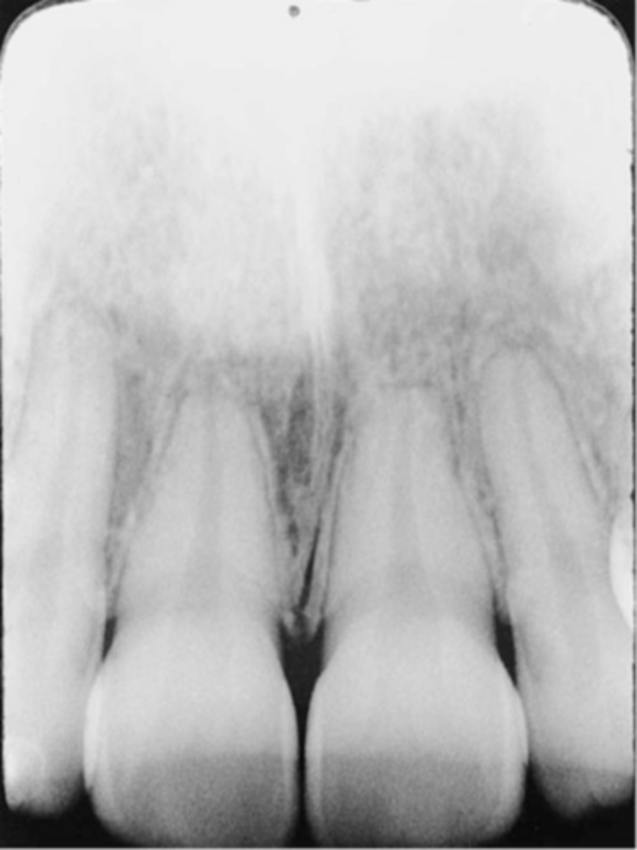
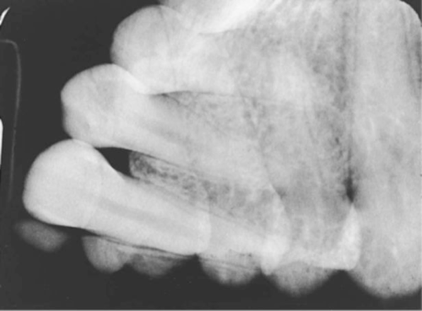
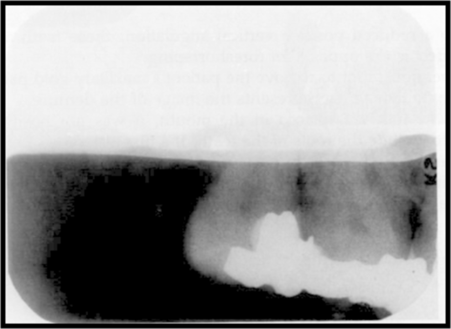
Film Bending
-Images appear stretched and distorted
-Film was bent excessively because of the curvature of the patient's hard palate
-Cotton rolls can be used to prevent this for the paralleling and bisecting technique or a film holding device.

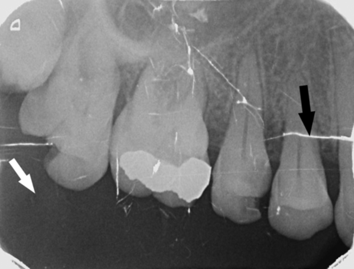
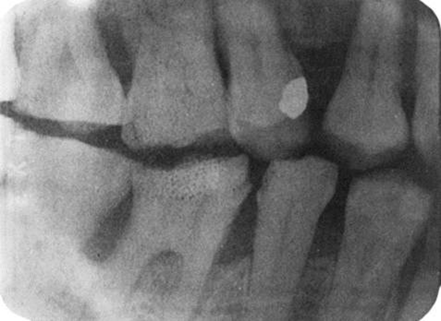
Film Creasing
-A thin radiolucent line is seen
-Film was creased and the emulsion cracked
-To prevent do not bend or crease the film, instead gently soften the corners before placing in the patient's mouth

Phalangioma
-Image of the patient's finger is seen
-Error occurs when the finger-holding method is used with the bisecting technique and is not recommended
-To avoid make certain that the patient's finger used to stabilize the receptor is placed behind the receptor and not in front of it

Double Exposure
-Double image is seen
-Same receptor was exposed twice in the patients mouth. This is a serious error and results in 2 retakes, one for each of the 2 areas previously radiographed
-To prevent always separate exposed and unexposed
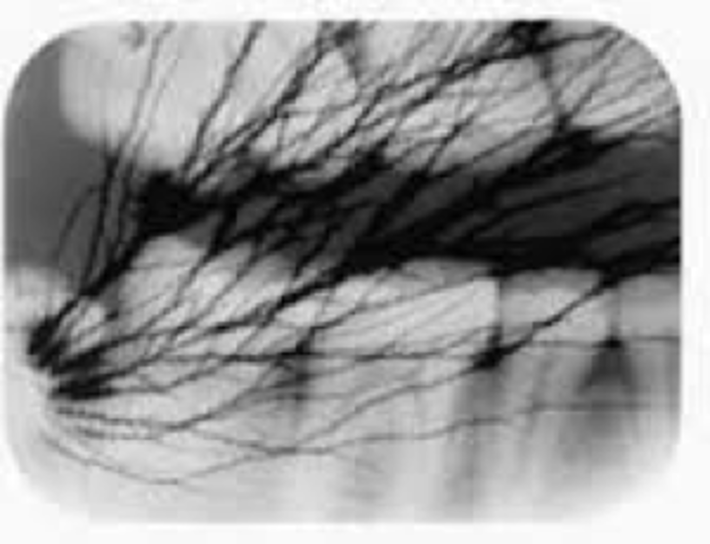
Movement
-Blurred images are seen
-Either the tubehead or the patient moved during the exposure of the receptor
Reversed Film
-Light images with a herringbone pattern are seen
-Film was placed in the mouth backward/reversed and then exposed
-To avoid always note the front and back sides of the film before placing it in the patient's mouth
Recognizing Radiographic Errors
A. Technique Errors
B. Processing Errors
C. Handling Errors
D. Fogged Image
Technique Errors-->Incorrect Positioning of the Image receptor
A. Not recording anterior structures
B. Not recording posterior structures
C. Not recording apical strutures
D. Not recording Coronal Structures
E. Slanting or Tilted Occlusal Plane
F. Reversed Film image error
G. Incorrect position of film Identification Dot.
Technique Errors
1. Incorrect Positioning of the Image receptor
2. Incorrect Position of the Tube Head and PID
3. Incorrect Exposure Factors
4. Misc. Errors in exposure technique
Image receptor-->Not recording anterior structures
Cause-Curvature and narrow arch, thick digital sensor, tori, sensor placement error
Correction-Place image receptor away from the lingual's of the teeth, toward the midline of the oral cavity.
Image receptor-->Not recording Posterior structures
Conditions-Common gagging reflex site (molars)
Cause-The image receptor is too far forward for the molars, or too far backward for the premolars in the mouth
Correction-Gain acceptance and assistance of patient
Tip for positioning the image receptor for exposure of a premolar radiograph
-Positioning the anterior edge of the image receptor against the canine on the opposite side places the image receptor into the correct anterior position.
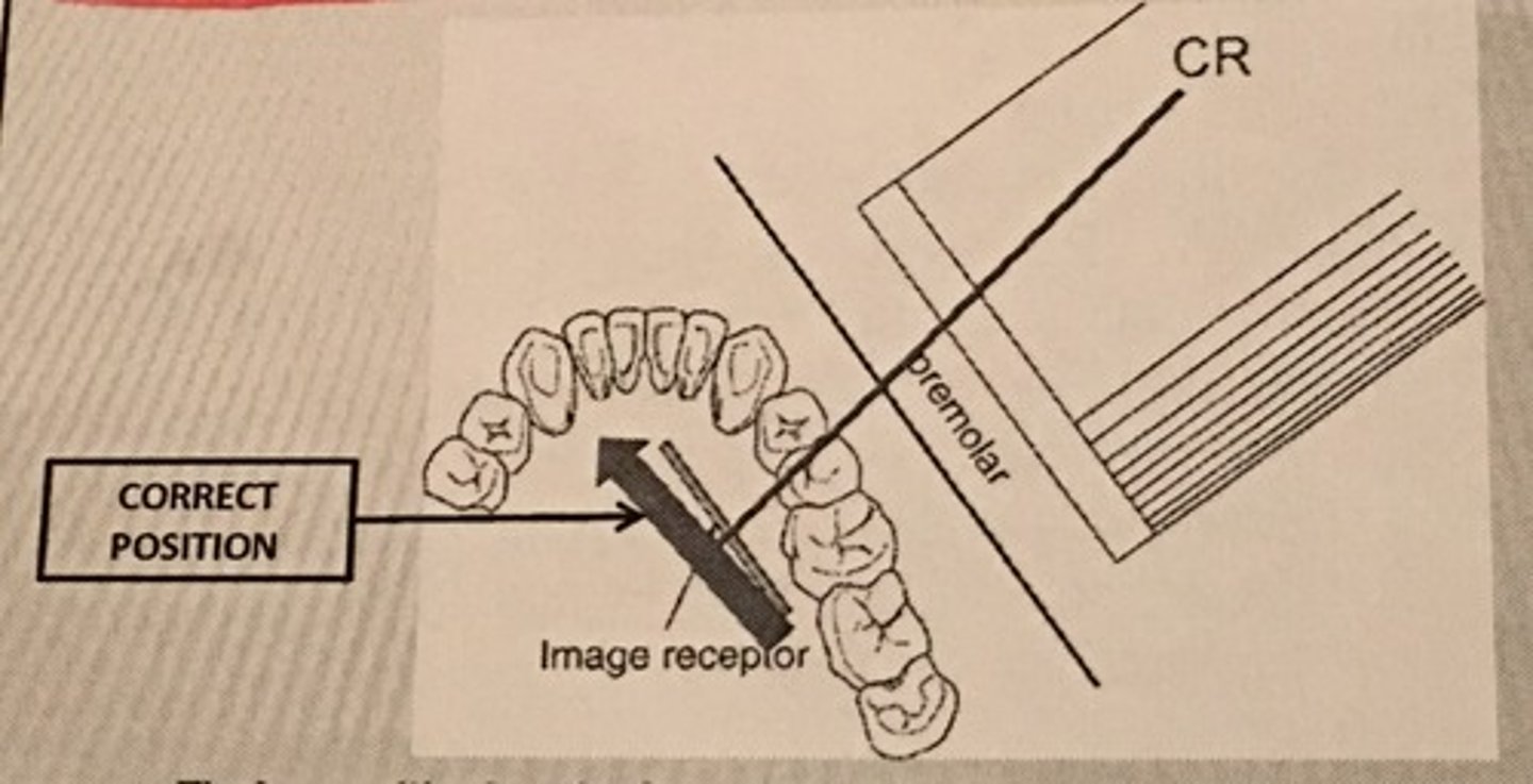
Image Receptor-->Not Recording Apical structures
Cause- Tori, uncooperative patient, deflected image receptor, elongation
Correction - Have pt. bite all the way down on bite block, place sensor away from the lingual's of the teeth to prevent deflection,
PID = Increasing vertical angulation by 10-15 degrees
Image Receptor-->Not recording coronal structures
Cause - Patient uncooperativeness, sensor placement error, Excessive angulation (too Steep)
Correction - Have pt. bite all the way down on bite block, secure the sensor in the slot of the bite block,
PID = Decrease vertical angulation by 10-15 degrees
Image Receptor-->Slanting or tilted occlusal Plane
Cause - Sensor placed on top of the tongue or gingiva, Improper positioning of the sensor in the slot, sensor edge not parallel with occlusal plane
Correction - Position the sensor away from the lingual surfaces of the teeth:
-Toward the midline of the palate (maxillary) slide the sensor to the lateral slide of the tongue (mandibular)
-Secure the sensor in the slot or bitetab
-Have pt. bite all the way down on bite block
Image Receptor-->Reversed Film Image Error (Herringbone error)
Cause - The image receptor film packet positioned backward - embossed lead foil pattern as an artifact
-Putting film or phosphor plate sensor in backwards causes mirror image and image to be less distinct.
Correction - Determine the front side (tube side) of the film packet prior to placing into the image holder.
Image Receptor-->Incorrect position of film identification dot
Cause - Dot can interfere with apex condition
Correction - Always place the dot toward incisal or occlusal plane
-"dot in the slot" for PAs
-"dot down" for Bite wings
-"dot out" for pedo #2 occ
Technique Errors-->Incorrect Position of the Tube Head & PID
A. Elongation of the image
B. Foreshortening of the image
C. Overlapped teeth contact
D. Cone-cut error
Tube Head & PID-->Elongation of the Image
-Bisecting technique error
-Insufficient Angulation (not steep enough), causing elongation or increased anatomy of the teeth and cutting off apex.
Tube Head & PID-->Foreshortening of the image
-Excessive angulation (too steep) causing shortening of the anatomy of the teeth and/or cutting off occlusal or incisal edge.
Tube Head & PID
1. PID Too steep Vertical angulation
2. Foreshortening of the image: Excessive angulation (Too Steep)
3. Elongation of the image: Insufficient vertical angulation
Tube Head & PID-->Overlapped teeth Contact
Cause - misdirecting the beam through the contacts, the x-ray beam/PID not perpendicular to the image receptor, Not positioning the image receptor parallel to the teeth
Correction - Move either mesial or distal depending on the mistake.
"Move toward it to fix it"
Mesiodistal overlap
-The x-ray beam is directed obliquely from mesial to distal
Cause - If overlapping is more severe in the posterior region, cone is angled too much form the mesial.
Correction - Shift the PID toward the posterior or direct the CR more from the distal
Distomesial overlap
-The x-ray beam is directed obliquely from distal to mesial
Cause - If overlapping is more in the anterior region, cone is angled too much from the distal
Correction - Shift the PID toward the anterior, direct the central ray beam more from the mesail
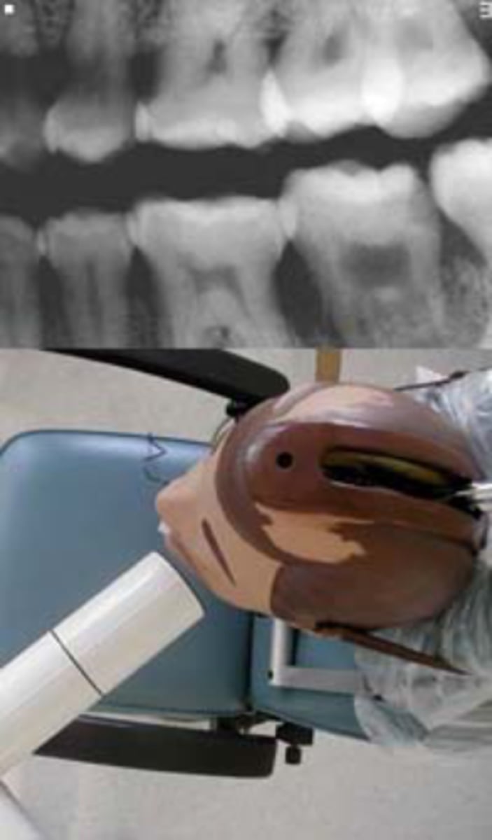
Tube Head & PID-->Cone-cut Error
Cause - Primary beam not directed toward the center of the image receptor or image receptor not lined up correctly to the PID
-Occurs more commonly without using XCP or external aiming device
Technique Errors-->Incorrect exposure Factors
A. Too light = underexposure
B. Too Dark = Overexposure
C. Blank Image = 1. Clear film, 2. Blank space of white,
3. Blank space of black Film
D. Double Image/Double Exposure
Exposure-->Too Light = Underexposure
-Low density (faint) image
-Too low kvp or mA
Incorrect Processing Factors
-Underdeveloped during processing
-Developer temperature too cold
-Developer concentration diluted
-Contaminated or old developer solution

Exposure-->Too Dark = Overexposure
-Too high kvp or mA
Incorrect Processing Factors
-Overdeveloped during processing
-Developer temperature too high
-Developer concentration too strong
-The film left in the developing solution too long
Exposure-->Blank Image
1. Clear film - Unexposed to x-ray, machine didn't expose the film prior to process
2. Blank space of white - Processed back side (back) of phosphor plate facing out in the laser scanner, or x-ray was exposed to the backside of the digital sensor
3. Blank space of black film - exposed to the light prior to the processing
Exposure-->Double Image/ Double Exposure
-Superimposed x-ray images
-Accidentally exposing film twice
-Maintain a systematic order to exposing radiographs
-FMX = Anterior to posterior
-BW = Premolars to Molars

Technique Errors-->Misc. errors in exposure technique
A. Poor Definition = Movement
B. Artifacts
C. Film crease
D. Film Deflection from Bending
Misc. errors-->Poor Definition
-Movement caused by the patient, slippage of the image receptor, or vibration of the tube head
-Gain patients cooperation, secure the image receptor in the holder
-Do not use the patients finger to stabilize the image receptor in the oral cavity
-Stabilize the tube head before activating the exposure
Misc. errors-->Artifacts
-Glasses, Phalangioma, Dentures, lead apron or thyroid collar
Misc. error-->Film Crease
-Radiolucent artifact
Misc. Error-->Film Deflection from bending
Processing Errors
1. Development Error
2. Processing and Darkroom Protocol errors
3. Chemical Contamination
Development Error-->Too light = Underexposed
-Underdeveloped during processing
-Developer temperature too cold
-Developer concentration diluted
-Contaminated or old developer solution
-Left in the fixer too long
-Left in the warm water too long
Development Error-->Too Dark = Overexposed
-Overdeveloped during processing
-Developer temperature too high
-Developer concentration too strong
-The film left in the developing solution too long
-Not enough time spent in the fixer or water

Development Error-->Reticulation
-Caused during film development by an excessive temperature difference between any 2 of the 3 darkroom solutions, the developer, the fixer, and the rinsing agent
Processing & Darkroom Errors-->Blank/clear image
-Film was placed in the fixer 1st by accident
-Film was in warm water too long, dissolved emulsion
-Solution - labeling the tanks prevents confusion
Processing & Darkroom Errors-->Partial Blank/Clear image
-Film manual processing error
-Blank image = Developer level too low to cover the entire film - the fixer will remove emulsion from the uncovered area and cause to it to clear the image
Processing & Darkroom Errors-->Partial Blank/White Image
-Digital or phosphor plate = Computer processing error.
-Laser scanner is off balance or bad connection
-A straight blank white border due to underdeveloped portion. The film may not be completely immersed in the developer solution
Processing & Darkroom Errors-->Partial Black Image
-Fixer level too low to cover the entire film = the developer will continue to darken the image
-Partial image: Fixer is too low to cover entire film
Processing & Darkroom Errors-->Green Film
-Film stuck together in the developer prevented from reaching emulsion (green)
-Common in using double film (2/pack). The 2nd film did not get separated prior to developing it.
Chemical Contamination
A. Black spots
B. Brown images
C. Spots/Stains
D. White Spots
Chemical Contamination-->Black Spots
-Contamination by developer
-Developer splash
-Dark spots caused by premature contact of film surface with developer
Chemical Contamination-->Brown Images
-Insufficient or improper washing = Film will turn brown over a period of several weeks after processing as the chemicals that remain on the surface of the film erode the image
-Rinse the films in the circulating water for at least 20 minutes
Chemical Contamination-->Spots/stains
-Iridescent, gray, and yellow stains can result when processing chemicals become exhausted or contaminated
-Air bublle
Chemical Contamination-->White Spots
-Contamination by fixer
-*Excessive wetting of phosphor plate with disinfectant will damage the image plate and will result in a digital image with missing information in the form of white or black spots.
Handling errors-->Artifacts Variation
A. Black image
B. Black pressure mark
C. Thin Black lines, Star-bursts, dots, lightening pattern
D. White lines or marks or blank image
E. smudged film
F. Black paper stuck to film
Artifacts-->Black Image
-Exposing film to white light, prior to processing, that portion of the image will appear black
Artifacts-->Black Pressure Mark
-Bending the film or excessive pressure to the film emulsion can cause the emulsion to crack
Artifacts-->Thin Black lines, Star-Bursts, Dots, Lightening Pattern
-When the film is pulled out of the packet wrapping too fast.
-Static electricity creates a white light spark that exposes (blackens) the film
Artifacts-->White lines or marks or Blank image
-Film emulsion is scratched from the base
-Damaged pixel from the digital sensors and phosphor plate
-Scratched film due to careless handling of the film
Artifacts-->Smudged Film
Cause - Handling the film with damp fingers or damp latex gloves, or with residual glove powder on the fingers will leave black smudges
-Avoid contact with the surface of the film. Handle by the edges only!
Artifacts-->Black paper stuck to film
-Possible due to contamination from the saliva
-Moisture softens the emulsion, causing the black paper to stick to the film.
Fogged Images
Film Fog = Formation of a thin, cloudy layer that compromises the clarity of the image (conventional film)
Fog or Electronic Noise (digital images) = Diminished contrast and make it difficult and often impossible to interpret the radiograph
Radiation Fog= Not protected from stray radiation before and after exposure
White light fog = White light leaking into the image receptor during processing
Fogged Images
Safelight Fog = Prolonged exposure to the safelight or the wattage of the safelight bulb is stronger than recommended
Miscellaneous Light Fog = Indicating lights, fluorescent faces of watches, computer screen, cell phone screens, etc. - extraoral film is hypersensitive to any light
Storage Fog = Heat, humidity, chemical fumes. Store film in a cool, dry area. Storing film in a darkroom is not recommended.
Fogged Image
Aged Film Fog = Film emulsion has a shelf life with an expiration date
Digital Radiographic Noise = Exposure setting too low
Re-exposing to scattered radiation = Too near the distance from the source of the x-ray after the initial exposure
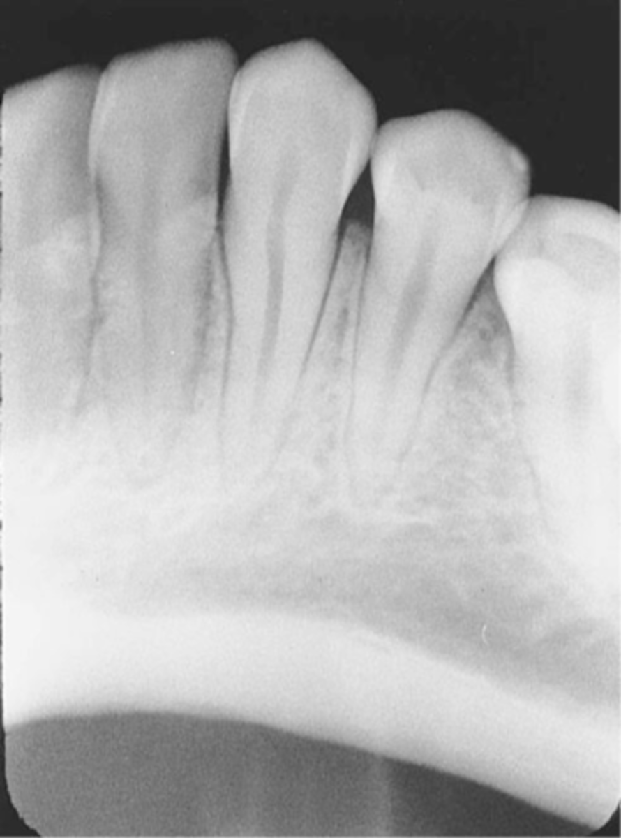
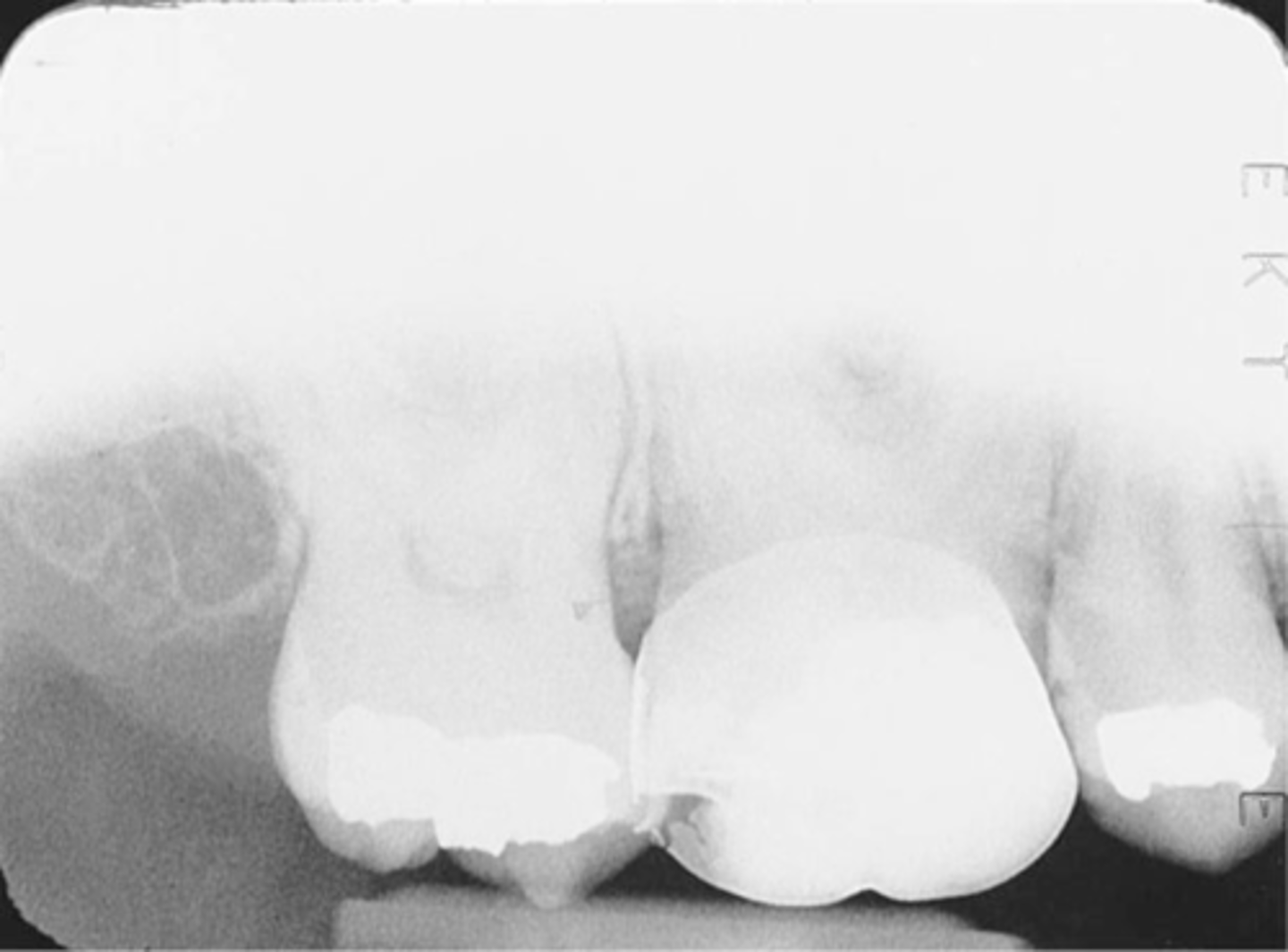
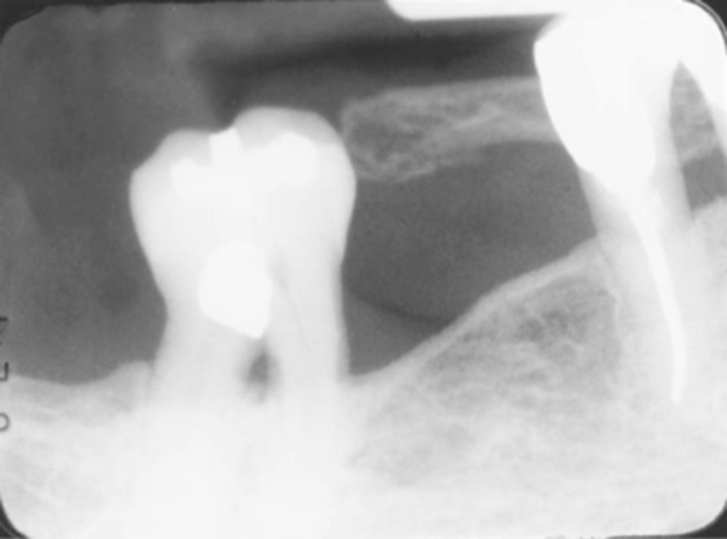
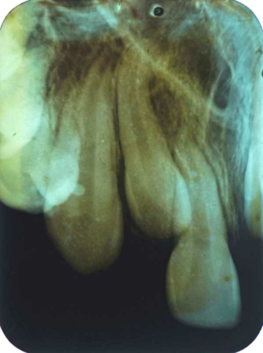
Incorrect Vertical Angulation
Underexposed
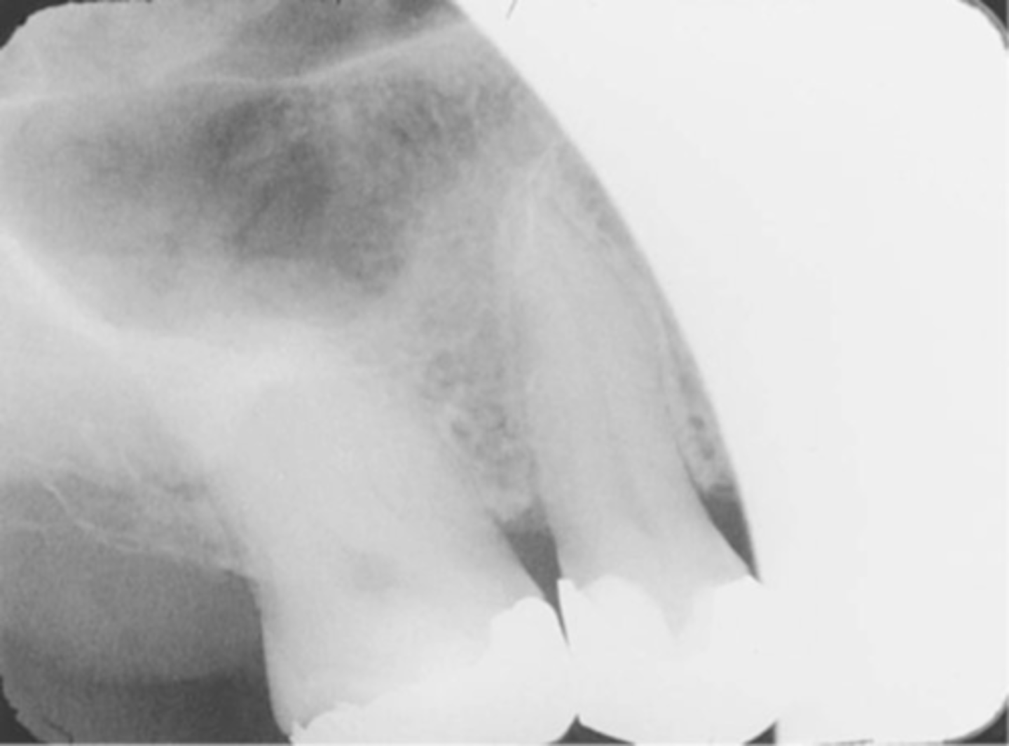
Movement Results in blurred image
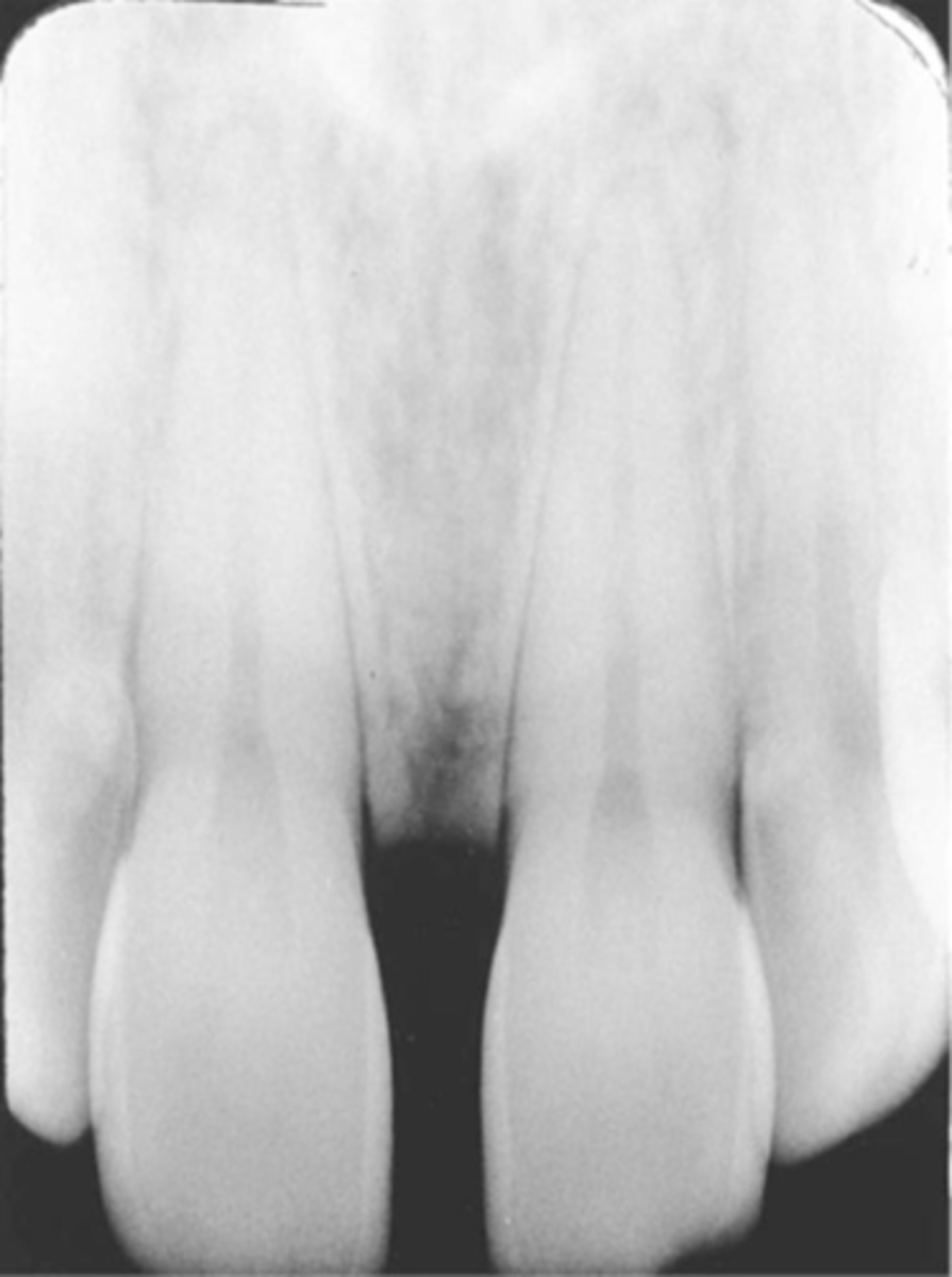
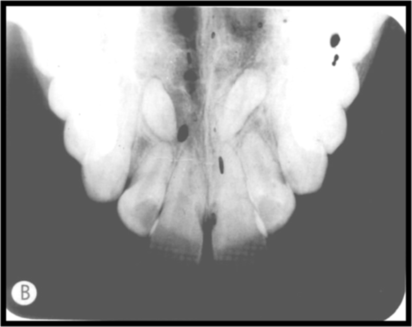
Bent Film
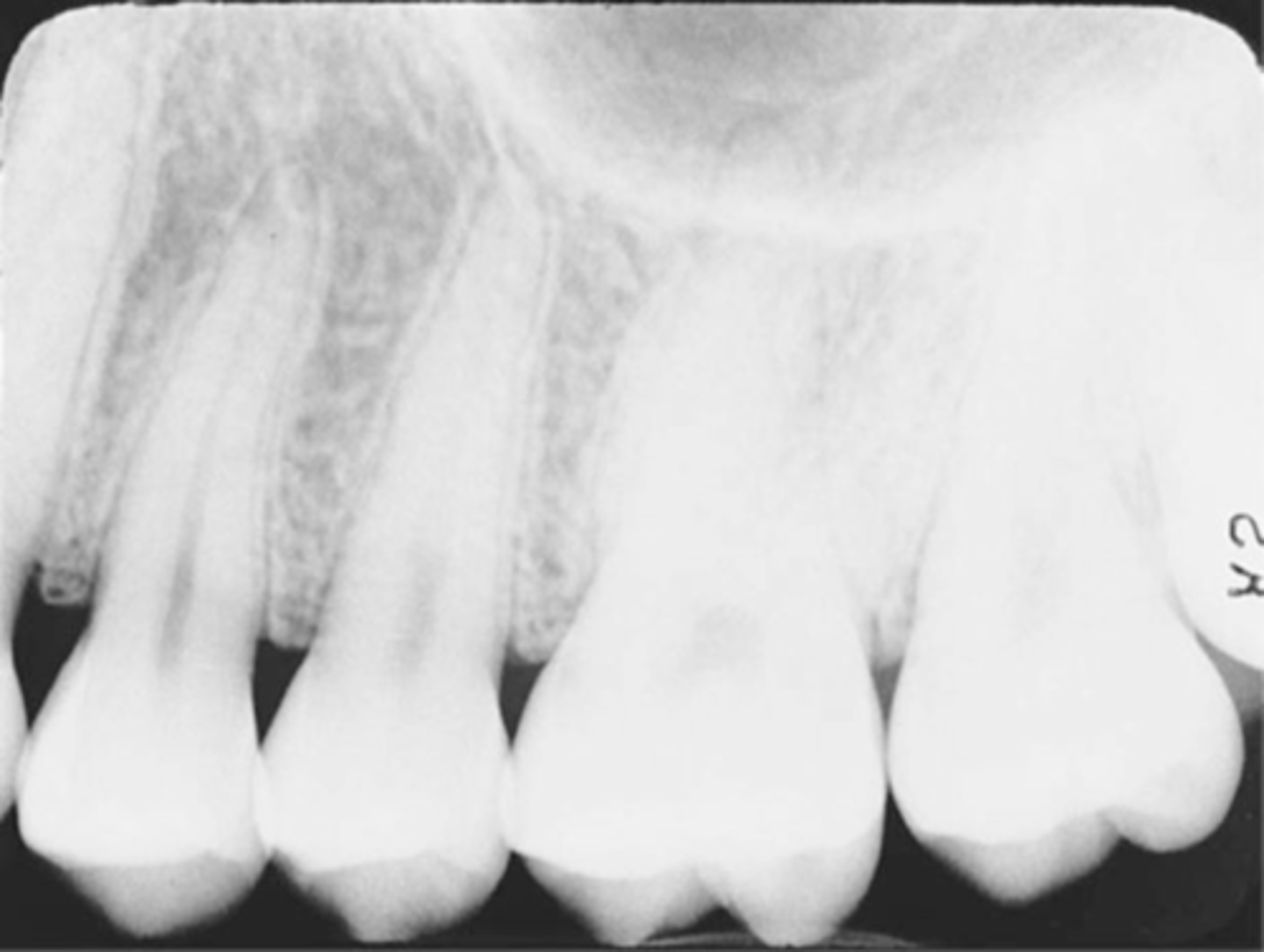
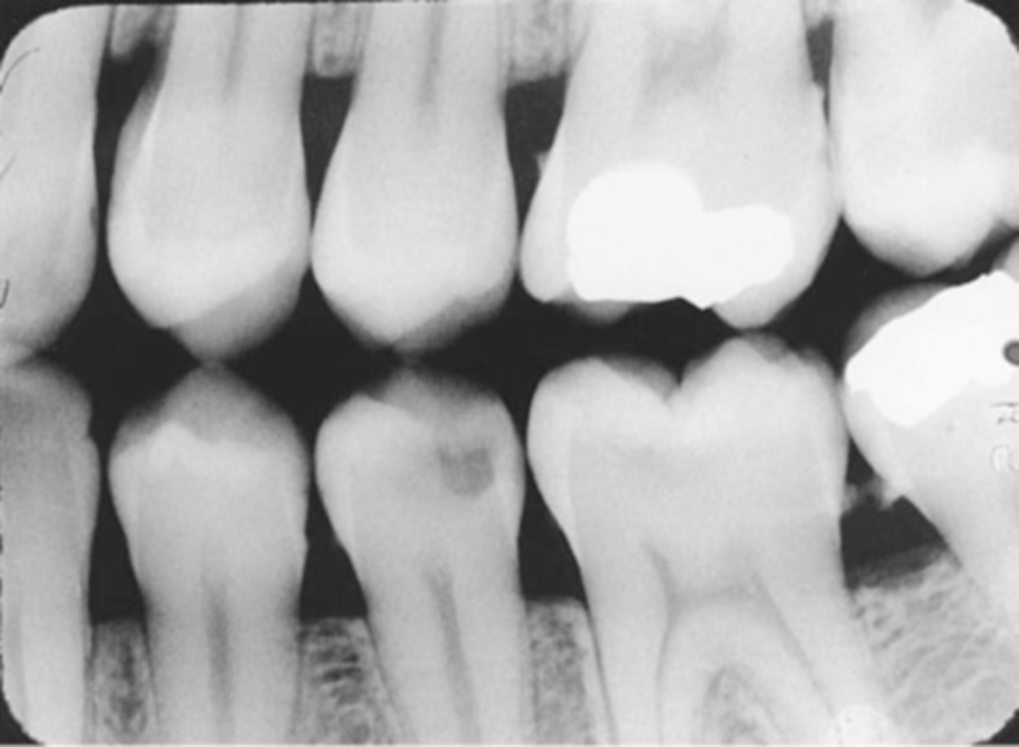
Reversed film with a herringbone/tire track pattern
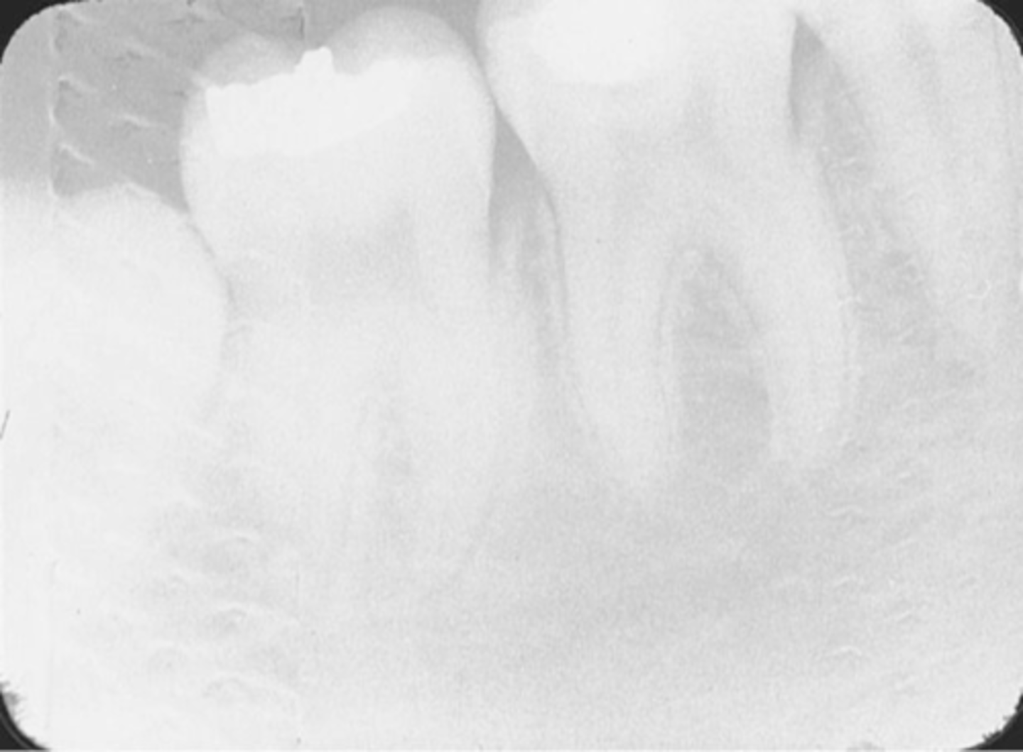
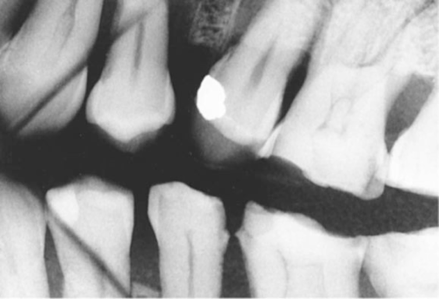
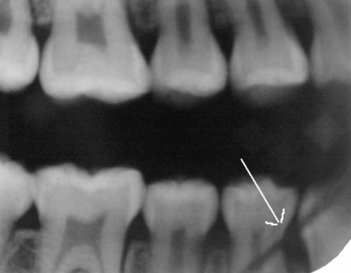
Cone-Cut
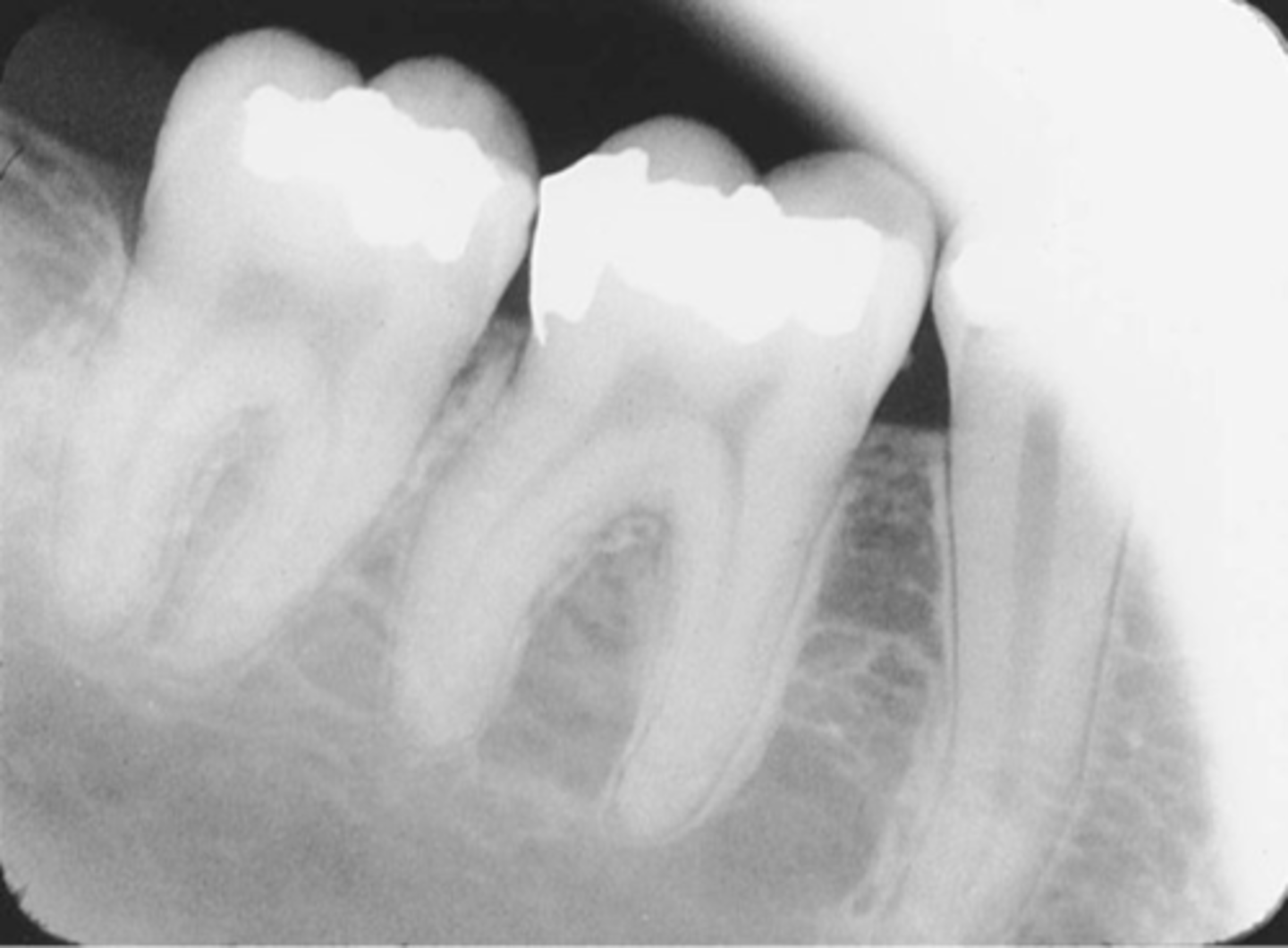
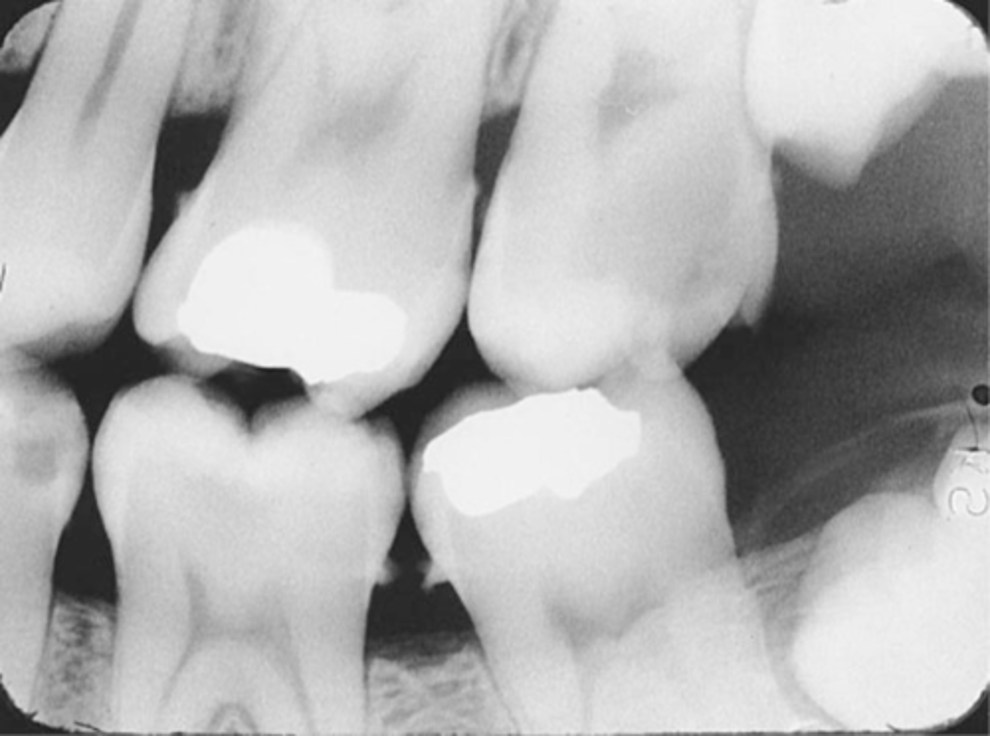
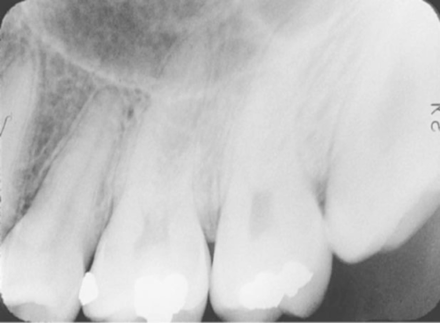
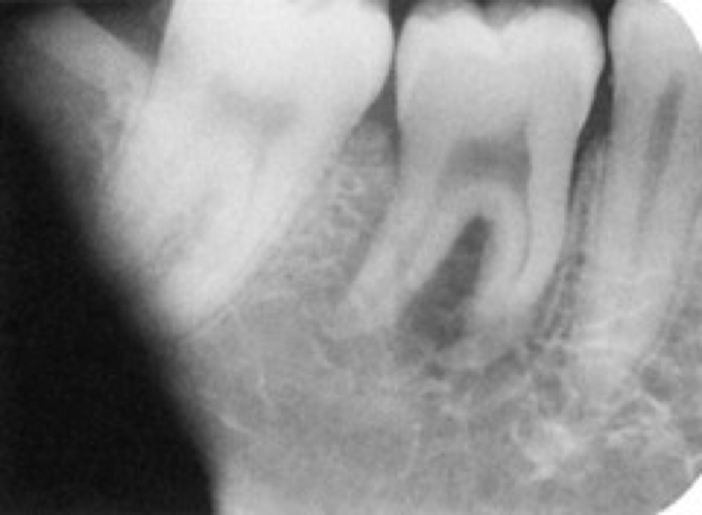
Overlapping
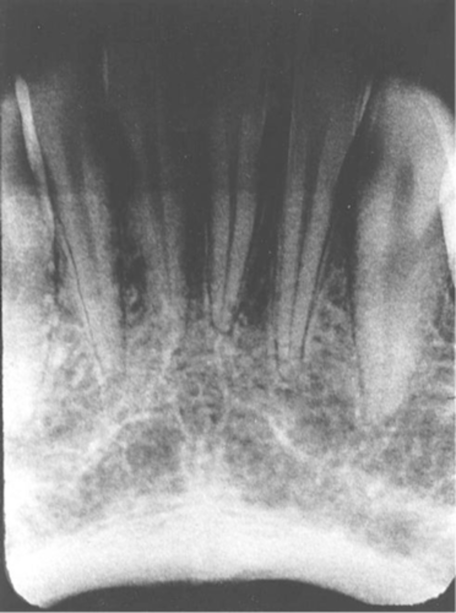
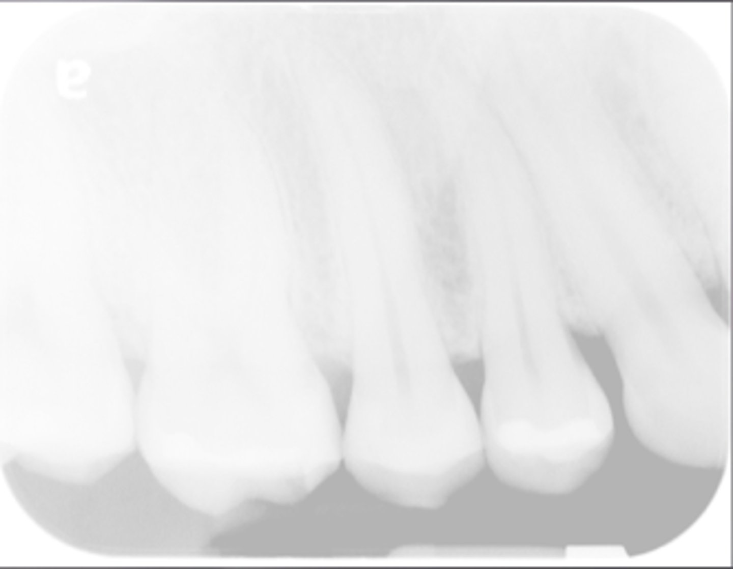
Overexposed
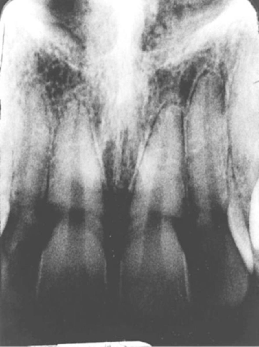
Foreshortened image; Vertical angulation is too steep, Possible deflected film.