StemUp: OCR A A level Physics 4.3: Electrical circuits
1/20
There's no tags or description
Looks like no tags are added yet.
Name | Mastery | Learn | Test | Matching | Spaced | Call with Kai |
|---|
No analytics yet
Send a link to your students to track their progress
21 Terms
What is Kirchhoff's second law? (1)
This states that in any circuit the sum of the electromotive force is equal to the sum of the potential difference in a closed loop.
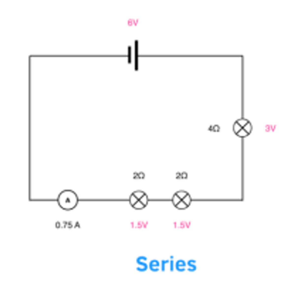
What is meant by components being connected in series? (1)
This is when components are connected on the same branch in an electrical circuit. It looks like:
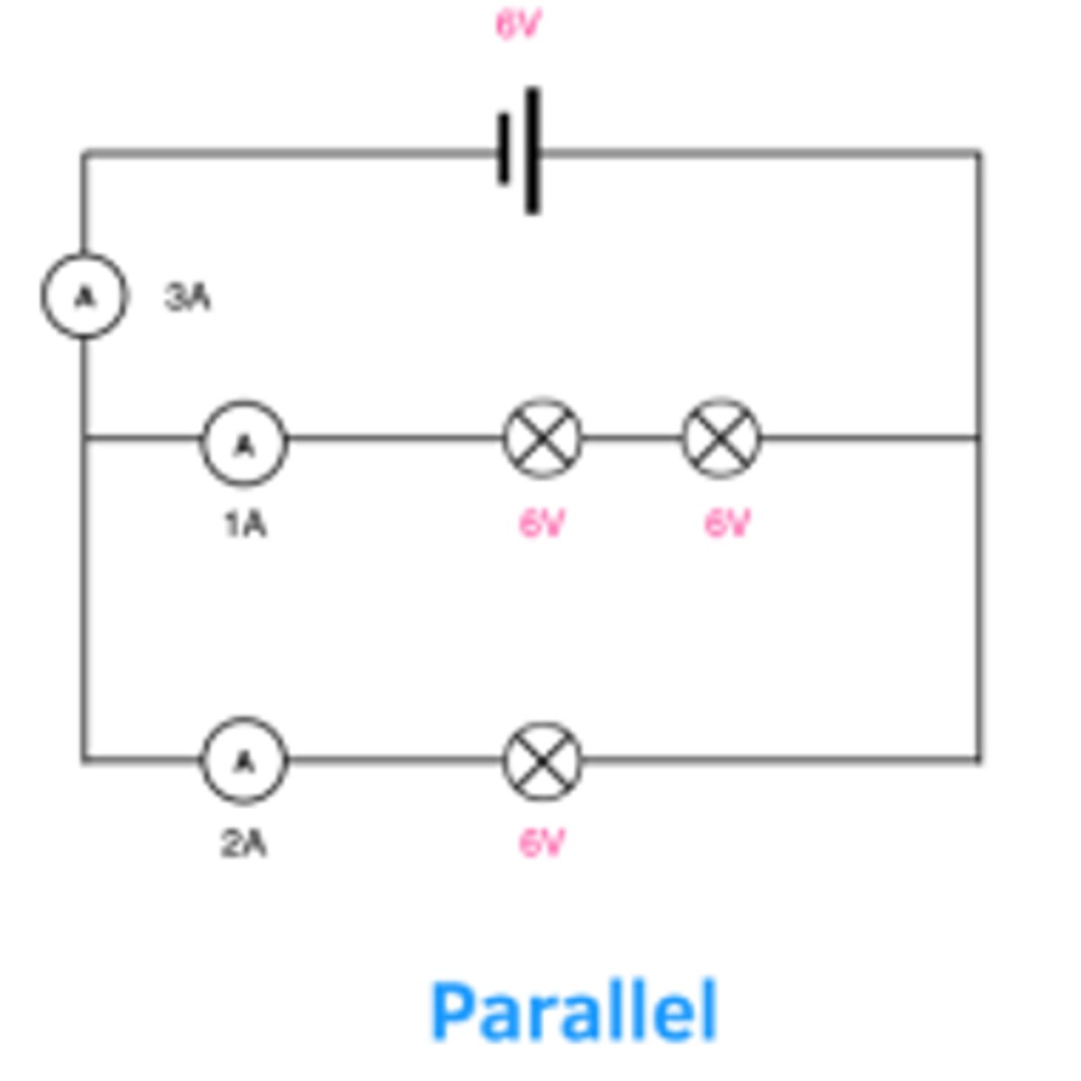
What is meant by components being connected in parallel? (1)
This is when components are connected on different branches in an electrical circuit. It looks like:
How does Kirchhoff's first law apply to electrical circuits? (2)
- In a series circuit, the current at each point will be the same as the current cannot branch out.
- In a parallel circuit, the current in each loop will add up to be the total current in the circuit. The current is greater in the loop with a smaller resistance as R = V/I
How does Kirchhoff's second law apply to electrical circuits? (2)
- In a series circuit, the potential difference is split between components and components of higher resistance will receive a greater share of the p.d. The total potential difference is equal to the emf of the cell.
- In a parallel circuit, the potential difference of each loop is equal to the total emf of the cell and the p.d. is split within the loop.
How is the total resistance of components connected in series found? (1)
This is given by the formula: R_{total} = R_1 + R_2 + ......
How is the total resistance of components connected in parallel found? (1)
This is given by the formula: 1 / R_total = 1 / R_1 + 1 / R_2 + .....
How does the current act in a series circuit? (1)
In a series circuit, the current at each point and through each component will be the same as the current cannot branch out into different loops.
How does the current act in a parallel circuit? (1)
In a parallel circuit, the current in each loop will add up to be the total current in the circuit. The current is greater in the loop with a smaller resistance as R = V/I. Inside each loop the current will remain constant for each component inside that loop.
How does the potential difference act in a series circuit? (1)
In a series circuit, the potential difference is split between components and components of higher resistance will receive a greater share of the p.d as more energy is transferred to them as V = W/Q. The total potential difference is equal to the emf of the cell.
How does the potential difference act in a parallel circuit? (1)
In a parallel circuit, the potential difference of each loop is equal to the total emf of the cell and the p.d. is split between components within the loop with higher resistance components receiving a greater share of the p.d.
What happens if the circuit has more than one source of e.m.f? (1)
The total input of emf to the circuit is just the sum of the two sources.
What is meant by internal resistance? (2)
Every source of emf has an internal resistance. It means that not all of the energy is transferred to the components in the circuit as some energy is transferred to the internal resistance of the source of emf.
What is the terminal potential difference? (1)
This is the potential difference that is supplied to the components in the circuit.
What is meant by lost volts? (1)
- This is the difference between the terminal p.d and the source of emf.
- It is equal to the potential difference across the internal resistance.
What is the equation for emf with an internal resistance? (2)
For a source of emf (ϵ) with an internal resistance (r) and attached to a resistor with resistance (R) with a current (I):
- The emf is given by: ϵ = I(R + r)
- As V = IR this can be written as ϵ = V + Ir where V is the terminal pd.
What is meant by a potential divider circuit? (1)
This is a circuit that divides the potential difference between two or more components.
What is a potentiometer? (2)
This is a type of potential divider circuit with a wire as one component in the circuit. The wire's length can be adjusted to change the share of p.d between the components and the wire.
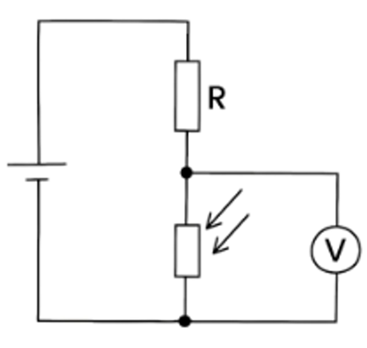
How is a potential divider circuit set up with a variable component? (3)
- This can look like the graph : -
- The variable component is one of the components in the potential divider circuit, when an event occurs that causes the variable components resistance to change the share of potential difference between the components change.
- In the diagram there is a light-dependent resistor (LDR), in bright light the resistance will decrease so the p.d across the LDR will decrease and across the resistor the p.d will increase.
What is the potential divider equation? (2)
This is given by: V_out = R_2 / R_1 + R_2 x V_in where V_in is the input terminal p.d, R1 is the resistance of the other component, R2 is the resistance of the component being measured and V_out is the p.d of this component.
How is the potential divider equation derived? (3)
- In a series circuit, the potential difference is split in a ratio directly proportional to the resistances of the components in the circuit:
V_1 / V_2 = R_1 / R_2
- This can be rearranged to: V_1 / R_1 = V_2 / R_2
- Considering the ratio for the resistance of one component to the current in the circuit, the potential difference across this component (with a resistance of R2) is:
V_out = R_2 / R_1 + R_2 x V_in where V_in is the input terminal p.d.