CSE3310 Midterm 1
5.0(2)
5.0(2)
Card Sorting
1/105
Earn XP
Description and Tags
Study Analytics
Name | Mastery | Learn | Test | Matching | Spaced | Call with Kai |
|---|
No study sessions yet.
106 Terms
1
New cards
Software Engineering
Engineering discipline that is concerned with all aspects of software production from conception to operation and maintenance
2
New cards
Differences between CS and SE
CS: Theories and methods/fundamentals of software systems
\
SE: Practicalities of developing software
\
SE: Practicalities of developing software
3
New cards
Confidentiality
Engineers should respect confidentiality irrespective of whether or not an agreement was signed
4
New cards
Competence
Not knowingly accept work that is outside their skill level
5
New cards
4 fundamental activities of SE
1. Requirements/specifications
2. Dev/Design and Implementation
3. Verification/Validation
4. Maintenance/Evolution
6
New cards
Requirements/specification
Where customers and engineers define software to be produced and constraints
7
New cards
Development/Design and Implementation
where software is designed and programmed
8
New cards
Verification/Validation
Where software is checked to ensure that it’s what’s required
9
New cards
Maintenance/Evolution
where software is modified to reflect changing customer and market requirements
10
New cards
Why not base project on prototype?
Prototype is to simply answer a question, not part of whole project since it’s build quickly w/ little care
11
New cards
Work products used for/created from REQUIREMENTS
artifacts, specifications
12
New cards
Work products used for/created from IMPLEMENTATION
source code
13
New cards
Work products used for/created from VALIDATION
Test cases, software w/ defects removed
14
New cards
Work products used for/created from EVOLUTION
artifacts, specifications, source code, test cases, software w/ defects removed
15
New cards
Steps of waterfall diagram
1. Requirements definition
2. System & software design
3. Implementation and unit testing
4. Integration and system testing
5. Operation and maintenance
16
New cards
Waterfall
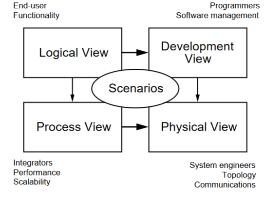
plan driven process that requires the previous step to finish b4 starting next one
17
New cards
incremental
based on idea of developing initial implementation, getting feedback, and evolving versions until required system has been developed
18
New cards
integration and config
Dev process focuses on configuring components for use in new setting and integrating them to the system.
19
New cards
Waterfall Pros
* Good for hardware development/high manufacturing costs.
* Predictable
* Good for stuff that requires planning
* Good for minimal change
* Predictable
* Good for stuff that requires planning
* Good for minimal change
20
New cards
Waterfall Cons
* Does not adapt to change well
* Lots of documentation
* If a step is incorrect, redo from said step
* No visibility
* Product isn’t ready until after completion
* Lots of documentation
* If a step is incorrect, redo from said step
* No visibility
* Product isn’t ready until after completion
21
New cards
Incremental Pros
* Parts are working earlier
* Deliver to customer earlier
* Get feedback during the design
* Not as document heavy
* Better than a waterfall approach for systems whose requirements are likely to change during the development process
* Deliver to customer earlier
* Get feedback during the design
* Not as document heavy
* Better than a waterfall approach for systems whose requirements are likely to change during the development process
22
New cards
Incremental Cons
* Refactoring problems: Redo structure of the code
* Lots of rework
* Erosion in clarity and quality
* More requirements
* System structure tends to degrade as new increments are added
* Lots of rework
* Erosion in clarity and quality
* More requirements
* System structure tends to degrade as new increments are added
23
New cards
Given these: which SDLC best describes this?
* Requirements known
* Requirements unchanged
* Customer desire
* No visibility
* Requirements known
* Requirements unchanged
* Customer desire
* No visibility
Waterfall method
24
New cards
Given these: which SDLC best describes this?
* Most functionality
* Short budget
* Short schedule
* Most functionality
* Short budget
* Short schedule
Integration and Configuration
25
New cards
Prototype
An early version of a software system that is used to demonstrate concepts, try out design options, and find out more about the problem and its possible solutions.
26
New cards
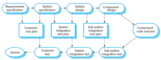
V-Model (photo)
\
27
New cards
V-Model
shows the software __validation__ activities that correspond to each stage of the waterfall process model.
28
New cards
Requirement
Fundamental to software engineering endeavors. Determine what the customer needs/wants and a basis of your product. Are what the functionality a program needs to have.
29
New cards
Functional Requirement
Something that the system will be able to do. Can you test it?
30
New cards
Nonfunctional Requirement
How the system will do something, and how well it does it.
1. applies to entire system
2. not in place
3. ility: readability, availability, security, efficiency
1. applies to entire system
2. not in place
3. ility: readability, availability, security, efficiency
31
New cards
Elicitation and analysis
Range of system stakeholders to find out about the application domain, services that the system should provide, required system performance, hardware constraints, other systems, etc.
32
New cards
Stages of elicitation and analysis
* Requirements Discovery
* Requirements classification and organization
* Requirements prioritization and negotiation
* Requirements specification
* Requirements classification and organization
* Requirements prioritization and negotiation
* Requirements specification
33
New cards
Validation
Concerned with demonstrating that the requirements define the system that the customer really wants
* Requirements error costs are high so validation is very important.
* Fixing a requirements error after delivery may cost up to 100 times the cost of fixing an implementation error.
* Prototyping is an example of this
* Requirements error costs are high so validation is very important.
* Fixing a requirements error after delivery may cost up to 100 times the cost of fixing an implementation error.
* Prototyping is an example of this
34
New cards
Management
Process of managing changing requirements during the requirements engineering process and system development.
* New requirements emerge as a system is being developed and after it has gone into use.
* New requirements emerge as a system is being developed and after it has gone into use.
35
New cards
Critiques for requirements
a. Vague
b. Conflicting
c. Not written as a requirement
d. Not testable
e. Non precise
f. More than one requirement in one sentence
b. Conflicting
c. Not written as a requirement
d. Not testable
e. Non precise
f. More than one requirement in one sentence
36
New cards
Purpose of software process
The activities and processes that are involved in developing and evolving a software system.
37
New cards
Steps of SEI Capability Maturity Model (SEICMM)
1. Initial
2. Managed
3. Defined
4. Quantitatively managed
5. Optimizing
Single arrow from each step pointing to the next one
38
New cards
SEICMM Initial
no process at all, free
39
New cards
SEICMM Managed
Basic schedule and planning, free
40
New cards
SEICMM Defined
Software process is defined, training of individuals
41
New cards
SEICMM Quantitatively managed
Measuring thing and use results to make things better, expensive
42
New cards
SEICMM Optimizing
Able to handle large changes with minimal hiccups, expensive
43
New cards
Stakeholder
Include anyone who is affected by the system in some way and so anyone who has a legitimate interest in it.
44
New cards
user requirements
1. Client managers
2. system end users
3. client engineers
4. contractor managers
5. system architects
45
New cards
System requirements
1. System end users
2. client engineers
3. system architects
4. software developers
5. stakeholders
46
New cards
problems with natural language specification
1. Lack of clarity
1. Precision is hard w/o making doc hard to read
2. Requirements confusion
1. Functional and Non-functional requirements tend to be mixed-up.
3. Requirements amalgamation
1. Several different requirements may be expressed together.
47
New cards
advantages of natural language specification
1. Expressive, intuitive, universal
2. Understandable by users and customers easily
48
New cards
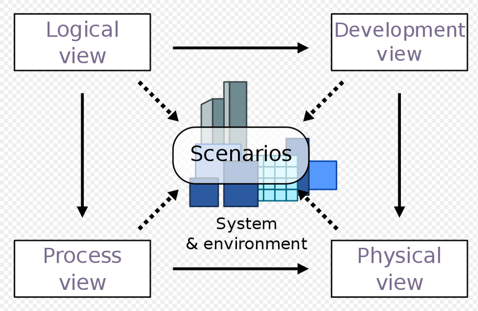
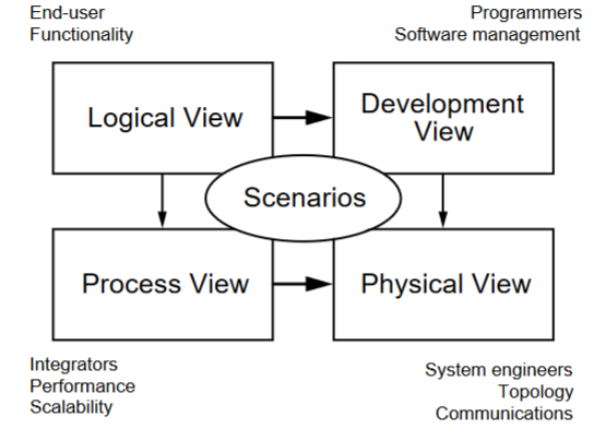
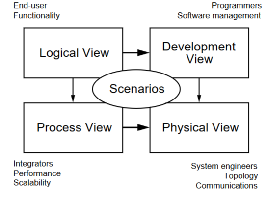
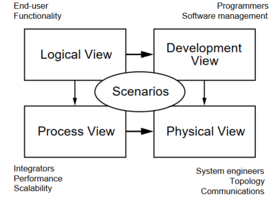
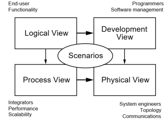
4+1 Model (image)
49
New cards
Way of writing system requirement specs: Natural language
The requirements are written using numbered sentences in natural language.
Each sentence should express one requirement.
Each sentence should express one requirement.
50
New cards
Way of writing system requirement specs: Structured Natural Language
The requirements are written in natural language on a standard form or
template. Each field provides information about an aspect of the requirement.
template. Each field provides information about an aspect of the requirement.
51
New cards
Way of writing system requirement specs: Graphical Notation
Graphical models, supplemented by text annotations, are used to define the
functional requirements for the system. UML (unified modeling language) use
case and sequence diagrams are commonly used.
functional requirements for the system. UML (unified modeling language) use
case and sequence diagrams are commonly used.
52
New cards
Way of writing system requirement specs: Mathematical Notation
These notations are based on mathematical concepts such as finite-state
machines or sets. Although these unambiguous specifications can reduce the
ambiguity in a requirements document, most customers don’t understand a
formal specification. They cannot check that it represents what they want, and
they are reluctant to accept it as a system contract.
machines or sets. Although these unambiguous specifications can reduce the
ambiguity in a requirements document, most customers don’t understand a
formal specification. They cannot check that it represents what they want, and
they are reluctant to accept it as a system contract.
53
New cards
Requirements Validation checks
Validity, Consistency, Completeness, Realism, Verifiability
54
New cards
Requirements Validation checks (in depth)
* Requirements reviews
* Systematic manual analysis of the requirements
* Verifiability, Traceability, Comprehensibility
* Prototyping
* Test-case generation
* Systematic manual analysis of the requirements
* Verifiability, Traceability, Comprehensibility
* Prototyping
* Test-case generation
55
New cards
Requirements spreadsheet
never reuse requirements ID, each one has a unique ID (UID)
56
New cards
How to determine if requirement ID is active
active flag will be on, or off (strikethrough), test cases for each of the requirements at the bottom
57
New cards
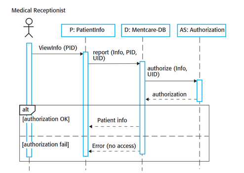
Sequences diagram
Shows interactions between actors and the system and between system components.
58
New cards
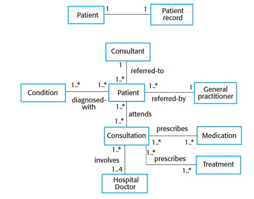
Class diagram
Shows the object classes in the system and the associations between these classes
Static type of diagram
Static type of diagram
59
New cards
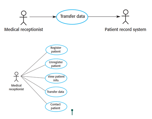
Use case diagram
Show interactions between system and it’s environment.
60
New cards
Be familiar with the following diagrams.
Use Case, Sequence, Class, Generalization, Aggregation, State, Process, Data Flow
61
New cards
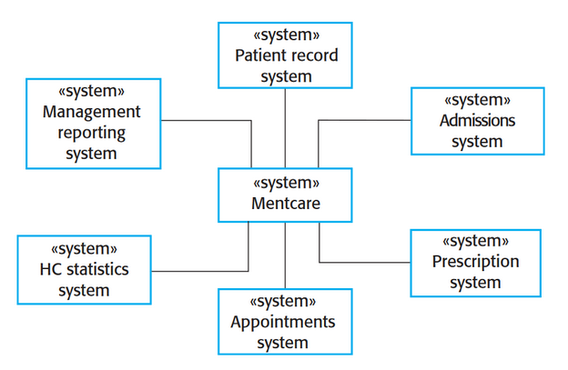
context diagram
Illustrates the separational context of a system
Shows what lies outside of system boundaries
based on perspective of center system
Shows what lies outside of system boundaries
based on perspective of center system
62
New cards
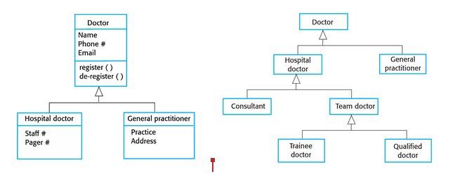
Generalization diagram
Rather than learn the detailed characteristics of every entity that we experience, we place these entities in more general classes (animals, cars, etc) and learn the characteristics of these classes. (OOP)
63
New cards
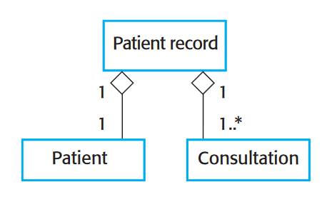
Aggregation diagram
shows how classes that are collections are composed of other classes
similar to part-of relationship in semantic data models
similar to part-of relationship in semantic data models
64
New cards
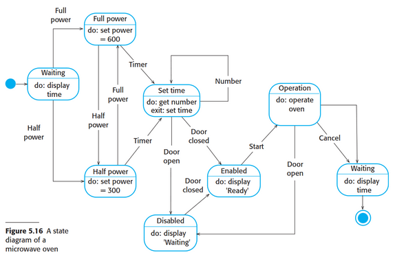
State diagram
shows how system reacts to internal and external events
65
New cards
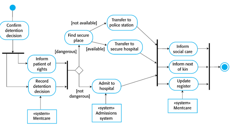
Process diagram
reveal how system is used in broader business processes
66
New cards
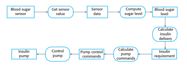
Dataflow diagram
Tracking and documenting how data associated with a particular process moves through the system help analysts and designers understand what is going on in the process
67
New cards
When to use: context diagram
Simple, shows dependencies and connections to others systems. Are good to show to managers and clients who don't know about the inner workings of the system.
68
New cards
When to use: use case diagram
Demonstrate the different ways that a user might interact with a system.
69
New cards
When to use: sequence diagrams
where it is important to understand how different objects or components interact with each other over time
70
New cards
When to use: class diagrams
When developing an object oriented system model. Objects are to be used to represent something in the real world
71
New cards
When to use: generalization diagrams
Specifically represent the inheritance hierarchy of classes in a system
72
New cards
When to use: aggregation diagrams
A big object that uses smaller objects but the smaller objects are independent of that big object and can be amongst different big objects.
73
New cards
When to use: state diagrams
Used to show system states and events that cause transitions from one state to another.
74
New cards
When to use: process diagrams
Whenever there is a need to understand, analyze, design, document, or communicate a process. Visualize the steps involved when designing a new process and the relationships between the steps.
75
New cards
When to use: data flow diagrams
Used to show how data flows within the system between processing steps. Simple and intuitive and so are more accessible to stakeholders.
76
New cards
Software Architecture
Concerned with understanding how a software system should be organized and designing the overall structure of the system.
Affects the performance, robustness, distributability, and maintainability of a system
Affects the performance, robustness, distributability, and maintainability of a system
77
New cards
Architectural Quote
"architecture is where non functional requirements are realized"
78
New cards
Why is architecture important?
* Architecture is where non-functional requirements are realized.
* The critical link between design and requirements engineering.
* Identifies main components in a system and relationships between them.
* Output is an architectural model that describes how a system is organized.
\
* The critical link between design and requirements engineering.
* Identifies main components in a system and relationships between them.
* Output is an architectural model that describes how a system is organized.
\
79
New cards
Example of non functional requirements being met by architecture
If system has to be fast, the architecture has to have low overhead.
80
New cards
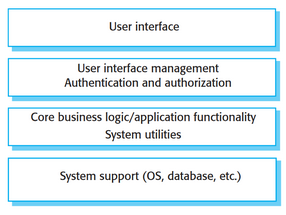
Layered Architecture
* Each layer only talks to the layer directly above and directly below it.
* Easy to switch layers out, only affects adjacent layers.
* Able to change one layer without touching other layers.
* Easy to switch layers out, only affects adjacent layers.
* Able to change one layer without touching other layers.
81
New cards
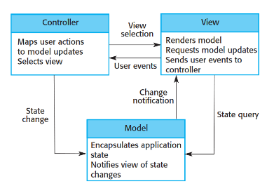
Model View Controller
* Breaks software into 3 pieces (Model, View, and Controller)
* View is highly changeable. Can easily swap the interface without touching anything else.
* View is highly changeable. Can easily swap the interface without touching anything else.
82
New cards
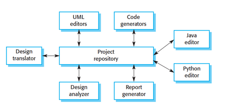
Repository Architecture
* Generally used for databases.
* Everything (data/info) goes into a center project repository.
* Minimizes coupling, components are independent of each other.
* Single point of failure.
* May be inefficient.
* Everything (data/info) goes into a center project repository.
* Minimizes coupling, components are independent of each other.
* Single point of failure.
* May be inefficient.
83
New cards
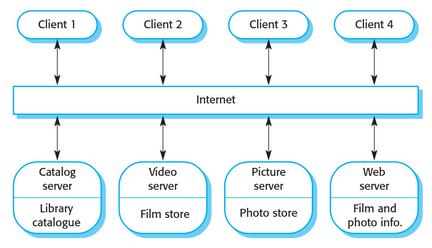
Client Architecture
* Client connects to many servers (many to one).
* Each service is a single point of failure, but multiple servers allows it to be robust.
* Modularity benefits and fault tolerant.
* Each service is a single point of failure, but multiple servers allows it to be robust.
* Modularity benefits and fault tolerant.
84
New cards
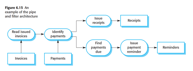
Pipe and Filter Architecture
* Output of 1 stage goes in as the input of another stage.
* Batch processing.
* Really easy to add another stage of processing, you only need to know what goes in and what is going out.
* Not good for things that demand responsiveness.
* Compilers are an example.
* Batch processing.
* Really easy to add another stage of processing, you only need to know what goes in and what is going out.
* Not good for things that demand responsiveness.
* Compilers are an example.
85
New cards
types of client architecture
* Thin: Client doesn’t have a lot of code/functionality
* Thick/Fat: More functionality (more JavaScript in a webpage), more responsive
* Thick/Fat: More functionality (more JavaScript in a webpage), more responsive
86
New cards
4+1 Diagram: Logical View
Concerned with the functionality that the system provides to end-users.
Class and state diagrams
End user functionality: connects to scenarios and development and process view
Class and state diagrams
End user functionality: connects to scenarios and development and process view
87
New cards
4+1 Diagram: Development view
Illustrates a system from a programmer's perspective and is concerned with software management.
Package and component diagram
Programmers, software development: connects to scenarios and physical view
Package and component diagram
Programmers, software development: connects to scenarios and physical view
88
New cards
4+1 Diagram: process view
Deals with the dynamic aspects of the system, explains the system processes and how they communicate, and focuses on the run time behavior of the system.
Addresses concurrency, distribution, integrator, performance, and scalability, etc.
Sequence/communication/activity diagram
Integrators, performance scalability: connects to scenarios and physical view
Addresses concurrency, distribution, integrator, performance, and scalability, etc.
Sequence/communication/activity diagram
Integrators, performance scalability: connects to scenarios and physical view
89
New cards
4+1 Diagram: Physical view
PoV of a system’s engineer. Concerned with the topology of software components on the physical layer as well as the physical connections between these components.
Deployment diagram
System engineers, topology, communications: connects to scenarios
Deployment diagram
System engineers, topology, communications: connects to scenarios
90
New cards
3 tiered layered web app architecture
In descending order: Display, business logic, database
Display usually at top and database at bottom, rest are interchangeable
Display usually at top and database at bottom, rest are interchangeable
91
New cards
Starting point
Base initial design on a generic application architecture. Specialize later for the system being developed.
92
New cards
Design checklist
compare design to generic app architecture, check for consistency
93
New cards
Organizing work
Assign work to people to implement different components within the architecture.
94
New cards
Accessing components for reuse
If there are components that may be reused, compare with generic structures to see whether there are comparable components in the application architecture.
95
New cards
Vocab for discussion
Use the concepts identified in the generic architecture to discuss and compare applications.
96
New cards
4+1 Diagram: Scenarios
Serve as a starting point for tests of an architecture prototype.
Use case diagram
Every other part connects to this, the “+1” part of the 4+1 diagram
Use case diagram
Every other part connects to this, the “+1” part of the 4+1 diagram
97
New cards
Integration & Config Pros
* Cheaper
* Available right away (faster)
* Reliable
* Available right away (faster)
* Reliable
98
New cards
Integration & Config Cons
* Does not do exactly what you want it to do.
* Evolution of the system is harder to do, some components are not controlled by you, so newer versions may not be in sync with what you want to accomplish.
* Evolution of the system is harder to do, some components are not controlled by you, so newer versions may not be in sync with what you want to accomplish.
99
New cards
Step 1 of 4 Fundamental Activities of SE
Requirements/Specifications
100
New cards
Step 2 of 4 Fundamental Activities of SE
Development/Design and Implementation