Unit three image production study guide
1/85
There's no tags or description
Looks like no tags are added yet.
Name | Mastery | Learn | Test | Matching | Spaced |
|---|
No study sessions yet.
86 Terms
§Anode Bevel
§The angle of the target surface of the anode in relationship to a vertical line drawn perpendicular to the long axis of the x-ray tube
§Affects:
§Effective Focal Spot (Line Focus Principle)
§Distribution of x-ray intensity within the beam (Anode Heel Effect)
Line Focus Principle
§Sharpness of details:
§Size of projected/effective focal spot is crucial for sharpness
§Focal Spot is determined by:
§Size of the filament (Cathode side)
§Angle of the Anode Bevel
§If anode bevel was 45 degrees, the effective focal spot would be identical to the beam of electrons from the filament would be
§In diagnostic x-ray it is MUCH steeper than that @ 15 - 17 degrees
§Goal: Achieve maximum sharpness while maintaining good heat dispersion
§mA Station selection depends greatly on the heat produced
Focal Spot Sizes
§Diagnostic X-ray
§Anode Bevel 15 -17 degrees
§Large Effective Focal Spot Size 1 – 2 mm
§Small Effective Focal Spot Size 0.5 – 1 mm
§Special procedures like Angiography & Cardiac Cath:
§Anode Bevel as shallow as 7- 10 degrees
§Fractional Focal Spot Size of 0.2 mm
§Even sharper images!
Effective focal spot
§Only 1 area
§The apparent size of the focal spot as perceived in a line perpendicular to the long axis of the x-ray tube (perpendicular to the electron beam)
§Projected focal spot
§Multiple numbers of projected focal spots which vary at angles to which they are perceived from any point along the IR
§Anode end is actually sharper (more detailed) than the Cathode side because of this
focal spot size
§The SMALLER the FSS the SHARPER the recorded detail on the image
§The Focal Spot is inversely proportional to image sharpness
§Larger FSS result in increased spreading of penumbra – the edges of the object are recorded several times from various locations
§More penumbra the more blurry the image
§The FFS is directly proportional to penumbra
§Double the size of the FS = doubles the spread of penumbra
§Reminder: as penumbra grows outward AND inwardinvading the umbral shadow (the good sharp portion of the image gets blurred too)
§3 variable control the projected geometrical sharpness:
1)FSS
2)OID
SOD
Anode Heel Effect
§Anode Side is USUALLY to the Radiographers LEFT as you would approach the table as it was installed
§Defined as the variation in the x-ray intensity along the longitudinal tube axis
§The x-ray intensity diminishes fairly rapidly from the central ray toward the anode side
§Anode acts as inherent filtration
§Heel of the anode = lower back corner of the anode disc
§Pronounce during:
§Steeper Anode Angles
§Larger Field Sizes see this effect more
§More pronounced on Large FSS
§Short SIDs amplify the problem
Using the Anode Heel Effect to our Advantage:
§Place the THINNEST portion of the anatomy toward the ANODE side of the tube
§Often we lay our patients with their heads to our left…
§Thorax – Shoulders to anode
§Thoracic Spine – Shoulders to the anode
§Reverse:
§Femur Feet nearest Anode
§Humerus- Elbow nearest Anode
§Foot – Toes on Anode end
§If thick body parts are placed on the anode side, they may be underpenetrated and thus mottle with be displayed on this portion of the image
Magnification
§The penumbra shadow gets recorded as magnification giving the entire image the impression that it has spread out larger
§The human eye locates the object’s edge as the middle of the penumbra
§Focal Spot Size DOES NOT affect TRUE MAGNIFICATION of the image
oIt is the primary controlling factor for sharpness ONLY
oSource to Image Distance
oDistance from the ANODE FOCAL SPOT to the IR
o3 Image Qualities it influences:
oUse the maximum feasible SID to improve
1)Exposure Level (follows the inverse square law)
2)Magnification
3)Sharpness (Recorded Details)
Measurements
uRed + or x engraved onto the anode end of the x-ray tube marks the exact location of the Focal Spot
uSID and SOD should be measured from here
uElectronic, Detents, or Tape measures
uTape measures somehow take the mounting position into consideration of adjustments from the anode’s FS
u6 foot tall Human’s Wingspan is 180 cm (72”)
uTheir opposite armpit to the tips of their fingers is then 100 cm (40”)
uMany companies are increasing their table their default SIDs to 110 or 115 cm
uThe 180 cm (72”) was established because the heart is represented only 3% magnified
Effect on Sharpness:
uWhen the SID is increased (moved farther away) the amount of blur/penumbra at the edges is reduced
uThe longer the SID the sharper the recorded detail
uIn reality it is the SOD that is directly responsible for the sharpness as in the sharpness calculations:
Sharpness = SOD/OID
SID Effect on Magnification:
uIncreasing SID reduces magnification of the image size
uWhen a longer SID is utilized the umbral portion of the image is reduced
uMagnification is usually wanted to be kept to a minimum
uTherefore, maximize to a feasible SID
uThe thicker the body part the higher risk of magnification to occur
uUsing bucky trays in the table/upright wall bucky, can pose a problem… increase SID
Effects on Exposure:
uInverse Square Law
uIf SID increases by a factor of 2, the area increases by 22 or 4 times
uIntensity of the radiation has spread out such that its concentration is now ¼ as much per square inch…
uCompensate the mAs by a factor of 4
uAny change greater than 15% of the SID should be compensated for in technique (changing the mAs)
uThe quality of the beam has not changed (kVp), so adjusting mAs for quantity is better in this instance
ØOr Vice Versa… if SID is cut in half = reduce to ¼ the mAs
Effect of reducing patient dose
uEven if you compensate for the increase in SID by increasing your mAs, the Entrance Skin Exposure (ESE or ESD – Dose) on the patient is reduced
uBecause Source to Skin Distance (SSD) is changed by a greater ratio than SID
u
uExample:
•A pt. 20 cm thick
•Increase SID from 100 cm to 125 cm (25% change)
•The SSD changes from 80 cm to 105 cm (31%)
•31% SSD vs 25% in SID bigger ratio of savings of dose to the patient… see page 346 for more info.
OID: Object to Image Distance
uEffect on Subject Contrast:
uSID = has no effect
uOID Does
uIncreases in OID has a positive effect on the subject contrast of an image
uReduces scatter (Air Gap Technique)
uThus reduces noise on the image
uThe intensity of the scatter radiation reduces drastically
uIt is beneficial to the DR system to start with the best SNR, so the system has the best chances at correcting issues… increasing OID reduces Noise
u= subject contrast by the remnant beam is increased
uBUT we don’t routinely increase OID for this purpose
Effects on Exposure:
uTo the IR:
uIncreasing the OID will result in a reduction in total exposure to the IR
uIf you needed to maintain the original exposure (technique) you should adjust the mAs by 35% when an increased OID is warranted (like during trauma radiography)
uTo the Patient:
uFollowing the inverse square law… increasing OID without increasing SID – the patient dose would increase due to being closer to the source
Effect on Sharpness & Magnification
uBucky trays always mess with both, no object can ever have 0 OID
uSharpness:
oThe larger the OID, the less sharpness of recorded detail
o
uMagnification:
oFor true magnification to be present the umbra must increase in size, not just the penumbra
Magnification Radiography or Macroradiography
uThe intentional use of long OIDs
uOID can be as larger as ½ of the SID
uResults in doubling of the image size (like a magnifying glass does)
uSmall details are made more visible, yet sharpness is decreased
uBecause of the undesirable blur that would come with this increase in mag – a much smaller “fractional focal spot size” needs to be used (0.2 mm)
Used inAngiographic procedures often
Magnification Ratio:
SID Image size
SOD or Object size
uRatio between the size of the image and the size of the object
uIf the SID:SOD ratio is 2 = the image is twice as large as the object
uIf the ratio is 1.5 the image has 50% magnification
uMagnification is always expressed as a ratio (% counts as a ratio)
uIf the increases in SID and OID are identical the magnification will be identical too
Sharpness Ratio:
SOD
OID
uIf SID and OID are again changed identically, the sharpness will not change either… it is maintained
uThey contain cancelling effects on each other for Sharpness and Magnification, but sharpness and magnification are not related!
off centering
•Divergence of X-Rays (Fanning out of the beam)
•Off centering has identical types of effects that angling has on the beam or part
•CR is the ONLY beam that is perpendicular to the IR
•A typical IR (17” =43 cm) at maximum can be off-centered by 20 cm
•@ 20 cm from the CR the beam divergence is 16 degrees
•We can correct for divergence by exchanging AP and PA projections
•If hand can not be laid flat, perform an AP projection rather than the PA
•Angles are also adjusted
üBe Careful to include the entire shadow in the projection
beam divergence con
•Beam is isotropically diverged in ALL directions
•At the following SID each centimeter away from the CR on the tabletop position adds about:
•100 cm – 0.7 degrees of angle for every cm away
•180 cm – 0.4 degrees of angle for every cm away
üTherefore a shorter SID can exaggerate distortion effects which are already present in the projection, although the SID, SOD, and OID are never the cause of the distortion, just can exacerbate the effects of the divergent ray!
üWe are used to routinely seeing the distortion present, so if it is off “norm” is when there are issues
SID AS A CONTRIBUTING FACTOR
•Once an object is already being distorted from off-centering, as shown below, reducing the SID places it in more divergent beams, increasing distortion
•SID does not cause distortion, but becomes a contributing factor once it is present
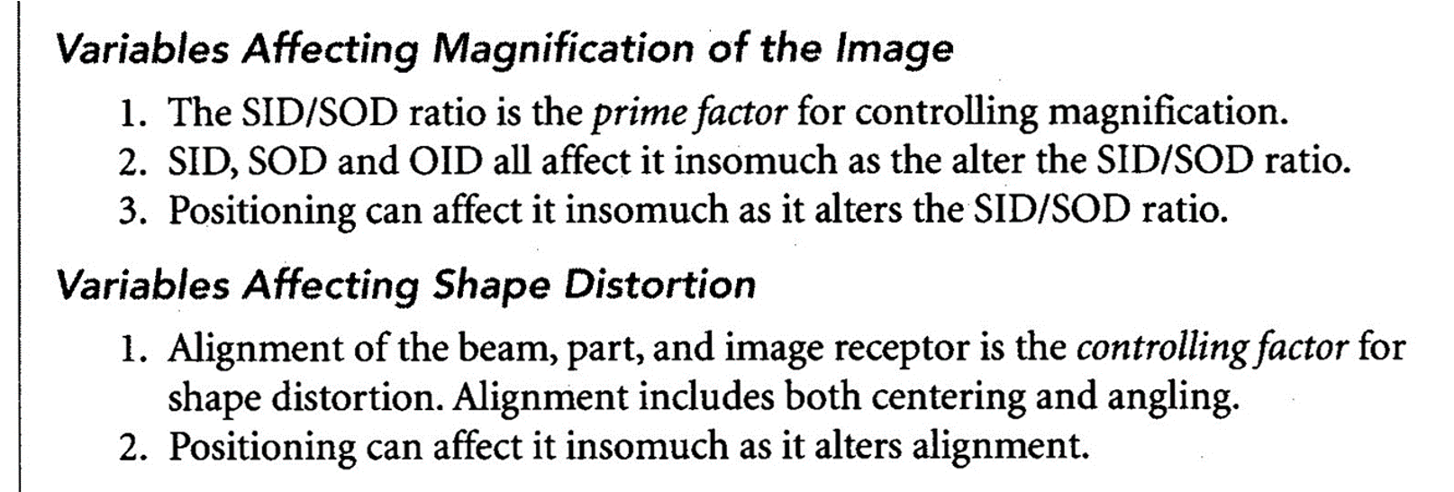
POSITION, SHAPE, AND SIZE OF THE ANATOMICAL PART
•Traditional rule:
•Keep the part parallel to the IR and the CR perpendicular to both the part and the plate to minimize distortion
•Not always possible
•De-superimposing
•The requirement of implementing angles to separate overlying anatomy of interest
•Shape Distortion must still be minimized
•Thicker anatomy causes more distortion than flat, tubular ones
•Spherical or cubical anatomy: Cranium, Femoral heads and condyles, Humeral heads, Vertebral bodies, and Tarsal bones
•Flat and/or tubular anatomy: Sternum, Scapular blades, Sacrum, Front teeth, Shafts of long bones, and Ureters
•Do not distort easily as long as their long axis is parallel to the plane of the IR
Foreshortening
•The image recorded is shorter in the axis of the tilt than the real object is
•Elongation:
•The image recorded is longer in the axis of the tilt than the real object is
CEISZYNSKI’S LAW OF ISOMETRY
•An isometric angle, equal to one-half the angle formed between the long axis of the object and the plane of the receptor plate, will eliminate or minimize distortion effects
•Compensates for tilted/angled anatomy in the patient while achieving minimal distortion of the image
•AP Sacrum:
•Sacrum is relatively flat bone that lies about 30 – 35 degrees angled to the IR in AP projection
•Yet, you angle only 15 degrees to compensate for the curvature
•This isometric angle allows one-half the anatomical angle of the sacrum to minimize shape distortion
(It also allows de-superimposition of the symphysis pubis
MAINTAINING EXPOSURE WITH ANGLING OF THE CR
•Angulation of the CR increases SID (Be sure to measure to put back to the wanted SID because…)
•Longer SIDs require more technique (Inverse Square Law)
•Rule of Thumb: Any time the Table Top Distance (TTD) is increased due to CR angulation more than 15 degrees you need to adjust your technique
•An angle of 15 degrees increases an SID by about 5% (100cm SID to 104cm SID for example)
•Or for every 5 degrees of angulation, reduce the TTD by 2.5 cm (remeasure your SID to get 40”!!!)
üAlso, be sure to think about how anatomy thickness could have changed?! Usually increases in thickness are seen with angulation
THE POSITIONING WHYS
•Positioning is based on these factors
1)Increase Sharpness
2)Reduce Magnification
3)Minimize Distortion
4)Increase visibility of the anatomy of interest by de-superimposing anatomy (This is a form of noise)
üProjections become routines
üThey set a standardization of quality of images
What would happen if a radiographer didn’t follow the standardization of projections?
MOTION
•Blurs sharpness
•Can be voluntary or involuntary
•Means of controlling motion on our images:
1)Patient cooperation (EDUCATE your patient – give clear instructions EVERY TIME)
2)Immobilization (sandbags, clamps, compression bands, sponges)
3)Short exposure times (involuntary motion, inebriated(drunk or high on something, not cooperating) , or pediatric patients)
•Peristalsis of the intestines (10 cm per second in the small bowel) and esophagus
•Gall bladder contractions can last 5 – 30 minutes
•Urinary tract (3 – 6 contractions per minute)
Breathing is considered voluntary in radiology as we can suspend their breathing!
MOTION DESTROYS SHARPNESS AND SUBJECT CONTRAST:
Sharpness
•Even small amounts of motion destroy sharpness of the image
•Immobilization can help
•Full cooperation of patient
•Good professional judgement when choosing when and what immobilizing devices to utilize
•Reduce exposure time: 0.033 seconds (1/30th of a second) can freeze motion for our images
Subject Contrast
•Can lighten or darken areas
•Motion can create false images that do not represent the real image at all (Noise)
resolution
•The ability of an imaging system to bring out the maximum number of details in an image
•The most visible information on an image
•Computer algorithms in digital processing can enhance these (Next fall semester!)
overall resolution
•The ability to distinguish the overall parts of an object or closely adjacent objects on an image
•Need to be able to be recognized as distinct and separate from each other
•Image Contrast (Contrast Resolution)
•Essential to make out their differences
•Measured in Modulation Transfer Function (MTF)
•Image Sharpness (Spatial Resolution)
•Essential to visually separate them
•Measured in spatial frequency
SPATIAL RESOLUTION/SPATIAL FREQUENCY
•Tested by imaging a lead foil line-pair template and measuring spatial frequency
•Measured in line pairs per millimeter (LP/mm)
•(Note: in digital systems pixel and dexel size are limiting factors)
•Produces alternating black and white lines in the image
•The observer scans the image until a point where the black and white lines are no longer distinguished as separate… the last recognizable line pair is the spatial frequency of that image
•The smallest absolute object that can be reproduced in this imaging system is proportional to ½ the spatial frequency
•(The smallest object that can be images is the size of one of the last stripes – black or white)
CONTRAST RESOLUTION/MTF
•Comparing how pitch dark each black line is with how blank white each white line is
•Penumbra disrupts contrast and spatial resolution
•Modulation Transfer Function (MTF) is the ratio of recorded contrast of an image to the real object’s subject contrast
•MTF is between 0 – 1
•1.0 would be perfect MTF
LATENT IMAGE
is the image that is unenhanced/unchanged/unprocessed by the computer
•We never really see it, as the computer algorithms change it prior to displaying our image for viewing
•In the past (Film Screen) the latent image was what appeared on the film prior to processing it in the dark room
SIX VARIABLES FOR THE REMNANT BEAM
1)Exposure
2)Subject Contrast
3)Noise
4)Sharpness of Detail
5)Magnification
6)Shape Distortion
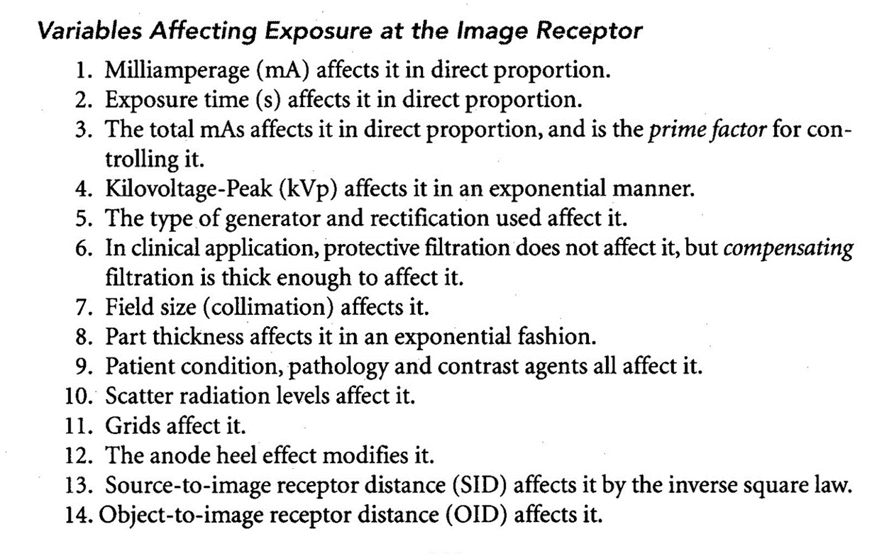
EXPOSURE

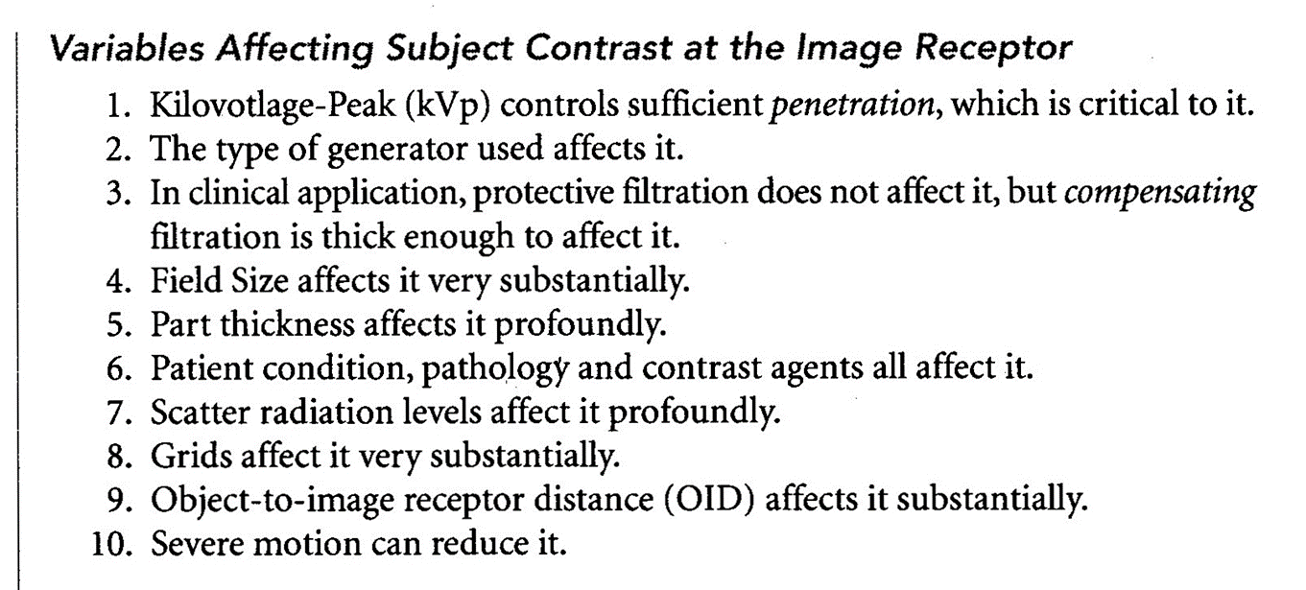
subject contrast


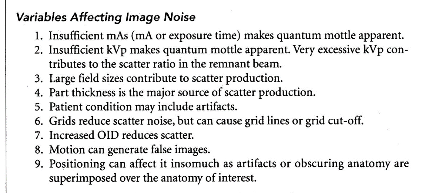
IMAGE NOISE
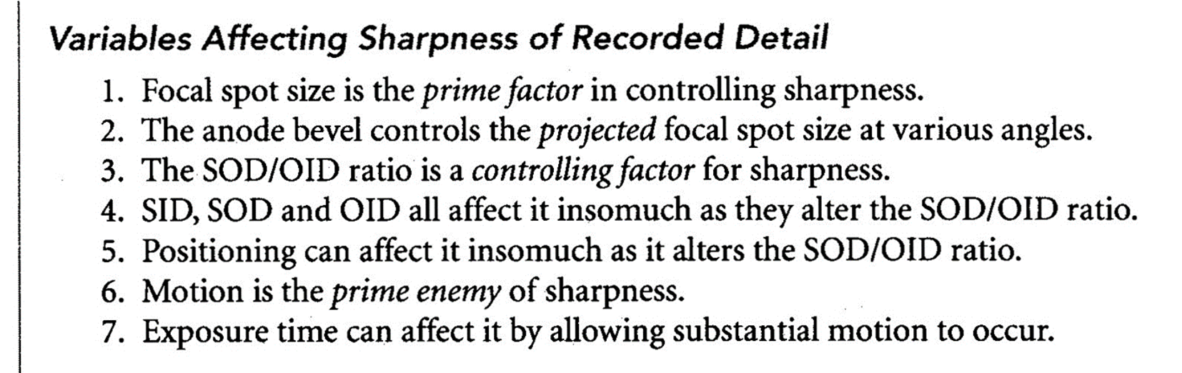
SHARPNESS

MAGNIFICATION AND SHAPE DISTORTION

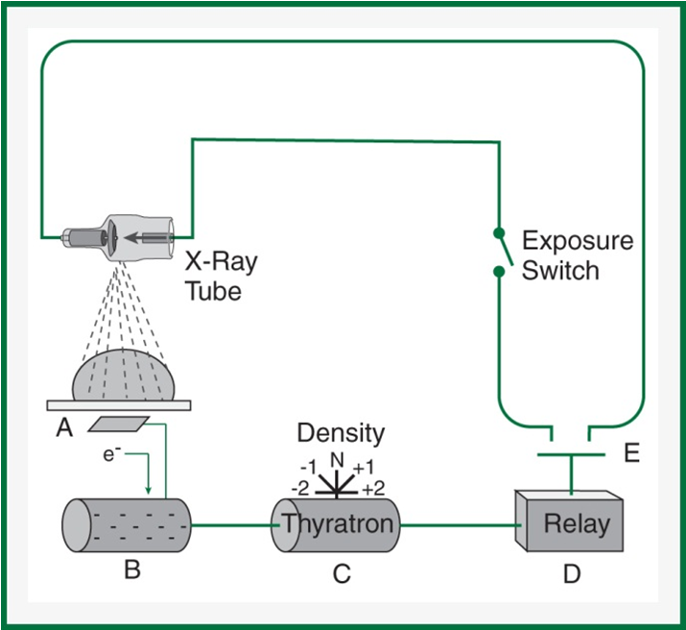
Automatic Exposure Controls -- AEC
■Created for achieving a more consistent exposure, and reducing retakes
■Saving radiation exposure to the patient
■Phototimer – named because we used to utilize the fluorescent screen with emitted light photons that was amplified by a photomultiplier to make an electric current
■Now we use: Gas ion chambers
created by Russell H. Morgan
1942
Aka… Phototimer
■Gas ion chambers
–Flat, rectangular, double-plated aluminum or plexiglass with a layer of gas encased in it
–The ion chamber induces an electrical current when the gas atoms are ionized by impinging radiation, freeing electrons from the gas atoms
–These electrons are attracted to and strike a positively-charged anode plate in the chamber change into an electrical charge
–This electrical charge is stored up on an electrical capacitor that reaches the preset threshold amount that corresponds to an ideal amount of exposure
–The Thyratron – releases the charge in a surge of electricity that activates an electromagnet.
–The electromagnet pulls open a switch to terminate the exposure
(are after the patient) OID grows
Minimum Response Time -- MRT
■The time is takes for a circuit to detect and react to the radiation received
■MRT range from 0.002 seconds (state of the art units) – 0.02 seconds (older units)
■Timing of exposure cannot be less than this
–Overexposure would result
–Radiographer needs to decrease mA to increase the seconds needed
Back–up Timer or
Back–up mAs
■AEC circuits can fail
■Need to prevent
–Excessive heat to tube (damage to the anode)
–Excessive and unnecessary radiation exposure to the patient
■Back up Timer
–Usually in older equipment
–Usually set at 1 ½ times (50%) the expected seconds needed
■So… 150% or up to 200% (Double expected timing of exposure)
–Never set longer than 2x the time
■Back up mAs
–Usually in newer equipment
–Usually 2x the expected mAs
–USUALLY 600 mAs MAXIMUM
Caution: Be sure to select correct bucky as bucky selection also activates the AEC for that specific location
AEC intensity (density) controls
■May still be labeled density controls
■Should be called intensity controls
■They are used to increase or decrease the preset sensitivity of the thyratron extending the time they are on
–Either reducing or increasing
qSmall, Average, and Large options
q½, ¾, N, 1 ½, and 2 options
q7 setting options: -3, -2, -1, N, +1, +2, and +3
üUsually represent a decrease or increase of 25%
5 Limitations of AECs
1)AEC should never be used on anatomy that is too small or narrow to completely cover at least 1 detector cell
2)Peripheral anatomy – proper positioning should never be compromised to allow use of the AEC
3)The tissue of interest, not just any anatomy, should cover most of the detector cells used
üPA CXR example – heart vs. lungs
4)The x-ray field must be well collimated to the anatomy of interest – scatter radiation will cause the AEC to shutoff prematurely
5)Radiopaque surgical prothesis/orthopedic devices (and other metal artifacts) will cause a much longer exposure than necessary
–Do not use AECs on patients known to have them
Detector Cell Configuration
■3 or 5 cells drawn on the bucky
■Some machines have a plastic insert that is placed in the collimator for easier location
–Needs to be used in a certain focal range
■Detector location
–Behind the tabletop or wall bucky
–Before the grid, imaging plate, and bucky tray
■Positioning
–Cover the activated cells with tissue of interest and the thickest portion of that anatomy
–Anatomy and patient size may change from “normal” detector selection
AEC Technique Charts
■Appropriate kVp
■Optimum mA
–Consider minimum response time for the system
■Back – up Timer or mAs
■Detector Selection
■Density Setting
■SID (sometimes)

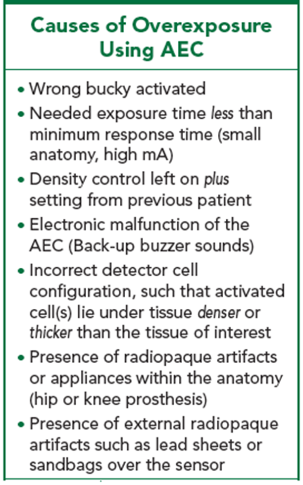
causes of overexposure using AEC
wrong Bucky activated
needed exposure time less than minumum response time (small anatomy, high mA)
density control left on plus setting from precious patient
electronic malfunction of the AEC (backup buzzer sounds)
incorrect detector cell configuration, such that activated (cells) lie under tissue denser or thicker than the tissue of interest
presence of radiopaque artifacts or appliances within the anatomy (hip or knee prosthesis)
presence of external radiopaque artifacts such as lead sheets or sandbags over the sensor
causes of underexposure using AEC
backup time shorter than needed exposure time (esp. on large patient)
density control left on minus setting from previous patient
inadequate collimation (excessive scatter radiation reaching sensors)
incorrect detector cell configuration such that activated cell(s) lie under tissue less dense or thinner than the tissue of intersst
detector cells not fully covered by the tissue of interest
anatomy too peripheral
anatomy part too small
specific tissue area too small
specific tissue area not centered over selected detector cells
15-17 degrees
What is the typical anode bevel angles for a general purpose x-ray tube?
left
x-ray tubes are conventionally installed with the anode to the R.Ts ….. as we approach the x ray table?
right
with the above information in mind, you should position the patient for an AP non-weight bearing foot with the patients head to your ….
increases
at a shorter SID, the collimator must be opened up to cover the same field size, so the anode hell effect: increases or decreases?
using a small focal spot with high mA could damage the anode because it can’t handle the heat load
why is the small focal spot not available when high mA stations are engaged?
the sharpness would increase and the spatial resolution would double
if the size of the focal spot is cut exactly in half, the sharpness of the image carried by the remnant x ray beam will change in which direction AND by how much
decreases
decreasing SID increases/decreases penumbra?
list 4 benefits of increases SID
reduces magnification
increases field of view
reduces entrance skin exposure (ESE)
improves spatial resolution
the SID was cut in half
if a change in SID (and all other factors the same ) has resulted in the exposure increasing by 4 times, the SID must have changed how:
15%
for any changes greater than …..% in SID, radiographic technique factors should be adjusted to compensate and maintain exposure
longest
in the interest of image sharpness, the ….. feasible SID should be used
shortest
in general x-ray, the …. possible OID should always be used to keep the imaged object closest to its original state
less
the greater the OID, the … sharpness/detail of the image
more
at a greater OID,…. rsidaiot is allowed to spread out more, this the air gap technique works
the same
an original magnification ratio is 50%. If the SID and OID are both tripled, the new magnification ratio is….
decreased
the distorting effects of off-centering are worsened when the Sid is increased/decreased
the cranium distorts more because it is thicker than the head of the femur. it is more round, making it further from the IR, causing more distortion
why does the cranium distort more than the head of the femur during angled projection?
alignment of the x ray tube
alignment of anatomy
alignment of ir
centrail ray direction
list the four aspects of beam-part receptor alignment with impact shape distortion
patient cooperation (give clear instructions)
immobilization (sandbags0
short exposure times
list three methods of minimizing motion during exposure
0.033 sec
to freeze motion, exposure time should not exceed … sec
lp/mm
what is the unit for spatial frequency
2 cms, and 1
a well developed technique chart will have a thickness measurement columns for every… cms of thickness change and alter only … technique variable from one view to the next within a radiographic series
optimum mA
the mA setting that provides the required quality of x-ray photons for adequate image quality while minimizing patient dose
mAs
exposure to the IR
kVp
penetration of the x ray beam
focal spot size
sharpness of detail in the latent image
sid and SOD
magnification of the latent image
alignment of beam, part, IR
shape distortion
correct patient position guidelines
appropriate detector cell selection
mAs settings
recommended kVp for each body part
4 items that should be included on an AEC technqiu chart
25% increase
what percent change does the +1 setting on the intensity/density controls do?
thickest
during AEC exposure, those detector cells activated should be covered by the … portion of anatomy