CP411- Graphics Programming
1/168
Earn XP
Description and Tags
Final Exam Prep
Name | Mastery | Learn | Test | Matching | Spaced | Call with Kai |
|---|
No analytics yet
Send a link to your students to track their progress
169 Terms
Graphics Hardware
What are the basic hardware components of computer graphics?
Display devices (monitors)
Video controllers
Memory
CPU
System bus
What are Display Devices used for?
They exist to display computer generated images to a screen. Some examples include CRTs, LCDs, and LEDs. There are two main approaches of displaying images on a screen: vector and raster
Vector Displays
Directly putting dots of objects onto the screen, dot by dot. We control the X/Y with the vertical/horizontal plat voltage and Z as the intensity.
Pros: as intuitive as drawing an image on paper with a pen, fast for simple images
Cons: needs to compute the position and colour of the next dot at the time of displaying the current dot, is expensive on devices and slow for complex images
Raster Display
Put all dots of objects into an image memory, then map the image in image memory to the screen - the image representation is created by dividing each image into lines, and each line into dots.
Pros: images are generated/stored ahead in raster which avoids displaying incomplete images, and since image generation and display are separated image display is independent of complexity
Cons: requires a separate memory for raster to store the image, requires high performance video controllers to scan raster to display, slow to render complex images and for interactive applications
Raster Pattern
Rectangular array of dots (pixels)
Scan Line
Row of pixels
Bitmap
Image represented by a raster pattern
Resolution
Number of pixels in an image, typically represented as the number of pixels per scan line times the number of scan lines.
e.g. 640×480 (640 pixels per row, 480 rows)
Color Depth
The number of bits stored in the frame buffer representing to the value of the pixel (its colour according to a specific colour model)
Video Controller
Scans each line of the raster in the frame buffer, sets the dot colour on the screen according to the value stored at the position in the frame buffer
Framebuffer
Memory block used to store data of all dots of a raster pattern line by line. It is a part of RAM and can be part of main memory or on a separate video card
Framebuffer Size
Determines the maximum resolution and colour depth of an image. It is equal to the resolution times the colour depth.
e..g 640×480×8 bits = 2 457 600 bits
Frame
A full scan and display of an image on a screen. These must be refreshed to draw new images since as new pixels are struck by electron beams, others are decaying - electron beams must hit all pixels frequently to eliminate image flickering
Frequency
Number of frames per second on the screen. e.g. 60 frames/second
Approaches to Scanning a Frame
Progressive scanning (scan lines sequentially)
Interlaced scanning (scan odd lines one by one, then scan all even lines sequentially)
Approaches to Rendering Objects to Framebuffer
Rasterization
Ray Tracing
Rasterization
For each object, compute and set the visible pixels of the object to the frame buffer.
Pros: faster and more efficient for real-time rendering. Widely used in GUI, video games and graphics applications
Cons: less accurate for complex lighting and reflection effects
Ray Tracing
For each pixel, create a ray from the eye to the pixel, compute the colour of an object that the ray hits, then set the colour of that pixel.
Pros: produces highly realistic lighting, reflections, shadows, global illumination effects. Widely used in film visual effects
Cons: computationally intensive, traditionally slower for real-time applications (but as GPU technology advances this becomes less of a problem)
Hybrid Rendering Approach
Utilizes rasterization for primary visibility and basic shading, and ray tracing for specific effects like reflections, shadows and global illumination
Video Cards
Hardware component whose function is to rasterize images in frame buffer and output images to the display. Its major components are the GPU and Video Memory
CPU vs GPU
CPU: does the model computing by sending graphic object model data to video memory and instructions to the GPU, which it process and rasterizes to generate pixel data that it stores in framebuffer
GPU: separate, self-contained computing devices dedicated for graphics computing that was much more computing power
Graphics Pipeline & Graphics Software
Scenes
virtual world made of objects that can be viewed; composed of instances of 2D/3D model objects
Primitives
Primary: supported by the hardware. Vertexes, line segments, and triangles
Basic: line strips (connected line segments), polygons (more than three vertices)
Extended: piecewise polynomial (spline) curves and surfaces with specific applications
Models
Representation of graphics objects (like cubes, triangles). Composed of primitives like vertexes, lines, triangles, and polygons
Rendering
Convert primitives from a scene to an image in frame buffer
Graphics Pipeline
Finer steps of the conversion from model to scene and to image in frame buffer
Rendering 3D Scenes
View the model objects in 3D Scenes
Rendering
Graphics object geometry
Modeling transformation
Lighting calculations
Viewing transform
Culling, Clipping
Projection transform
Rasterize
Framebuffer
Display
Coordinate Systems
Modeling (MCS): local, represent an object model
World (WCS): global, represent all object instances in a scene
Viewer (VCS): local coordinate of the viewer
Normalize device (NDCS): internal system
Device/Screen (D/S CS): external system
Transformations
Model (MCS to WCS): scale, translate, rotate and their composite to put each model instances into its position in a virtual world or scene
View (WCS to VCS): bring objects into viewer coordinates
Projection (VCS to view plane, NDCS): projects objects into a view plane from 3D to 2D
Display (NDCS to DCS): mapping the clipping window to the display window
Projections
Parallel: projecting a vertex to view plane along one direction. Everything follows the same view plane. Usually used in 2D graphics
Perspective: projecting a vertex to view plane by ray from eye to the vertex. Mimics real-life perspective. Usually used in 3D graphics
Culling and Clipping
Culling: remove hidden primitives, e.g. objects or parts covered by other primitives
Clipping: remove or modify primitives if they are not within the viewing portions
Lighting and Shading
Lighting: determines the colour intensity of vertices of a primitive based on light models. This can be added in the rendering process according to the light sources and reflection features of objects
Shading: determines the colour of each pixel of a primitive, using the vertex colour or a texture and shading model, i.e. what colour to make an object
Scan Conversion
Step in the graphics pipeline that converts primitives to pixels on screen. Determines the coordinates and colours of all pixels of these graphic primitives. They are implemented in either hardware (primary primitives) or software (basic or extended primitives)
Algorithms in Graphics Pipeline
Fundamental: transformation, culling & clipping, lilting & shading, scan conversion
Advanced: animation and interactive graphics
Graphics Software
Package consisting of implementation of the graphics algorithms for certain graphics purposes
OpenGL Programming
What is OpenGL?
Standard specification defining a cross-platform Application Program Interface (API) for writing 2D and 3D graphics application programs. Includes necessary APIs for graphics pipeline operations.
What does OpenGL Cover?
Covers certain operations of the graphics pipeline:
Geometry transformations, projections
Culling, clipping
Lighting, shading
Scan conversion (rasterization)
Why is OpenGL a Standard?
Does just enough for graphics pipeline operations
Relatively stable without many changes, extensible
Open sourced, well managed and supported
OpenGL Extended Libraries
OpenGL utility Library (GLU)
OpenGL Utility Toolkit (GLUT)
OpenGL Extension Wrangler Library (GLEW)
OpenGL Utility Library (GLU)
Functions to simplify the routines from OpenGL in more human-friendly terms. Features include setting up viewing and projection, describing complex objects with line and polygon approximations, and provides additional primitives for use in OpenGL applications.
OpenGL Utility Toolkit (GLUT)
Primarily performs system-level I/O with the host operating system. Functions include window definition, window control, and monitoring of keyboard and mouse input. Features include routines for drawing geometric primitives and routines to create and interact with pop-up menus.
OpenGL Extension Wrangler Library
Cross-platform open-source C/C++ extension loading library that provides efficient run-time mechanisms for determining which OpenGL extensions are supported on the target platform.
Characteristics of OpenGL Application Programs
Model-view-control (MVC)
Event-driven
Client-server model
State machine
Model-View-Control
2D/3D models, rendering and display as view, change of graphics as control. Commonly used for developing GUI interactive applications
Event-Driven
The flow of an OpenGL program is determined by events such as user actions. The event loop is used to check for new events and dispatches them to the appropriate event handlers
Client-Server Model
Application program code used OpenGL commands act as the client, serve is the OpenGL implementation running on the GPU
State Machine
OpenGL maintains a collection of state variables that define how it should currently operate. State changes are made through OpenGL API calls. The current state affects how subsequent drawing commands are executed.
Scan Conversion for Lines & Circles
Simple Algorithm for Coordinates
Use the same colour for all pixels in a line
Interpolate the colours of the lines’s end points
Incremental Algorithm
Calculate the next pixel by using the current one
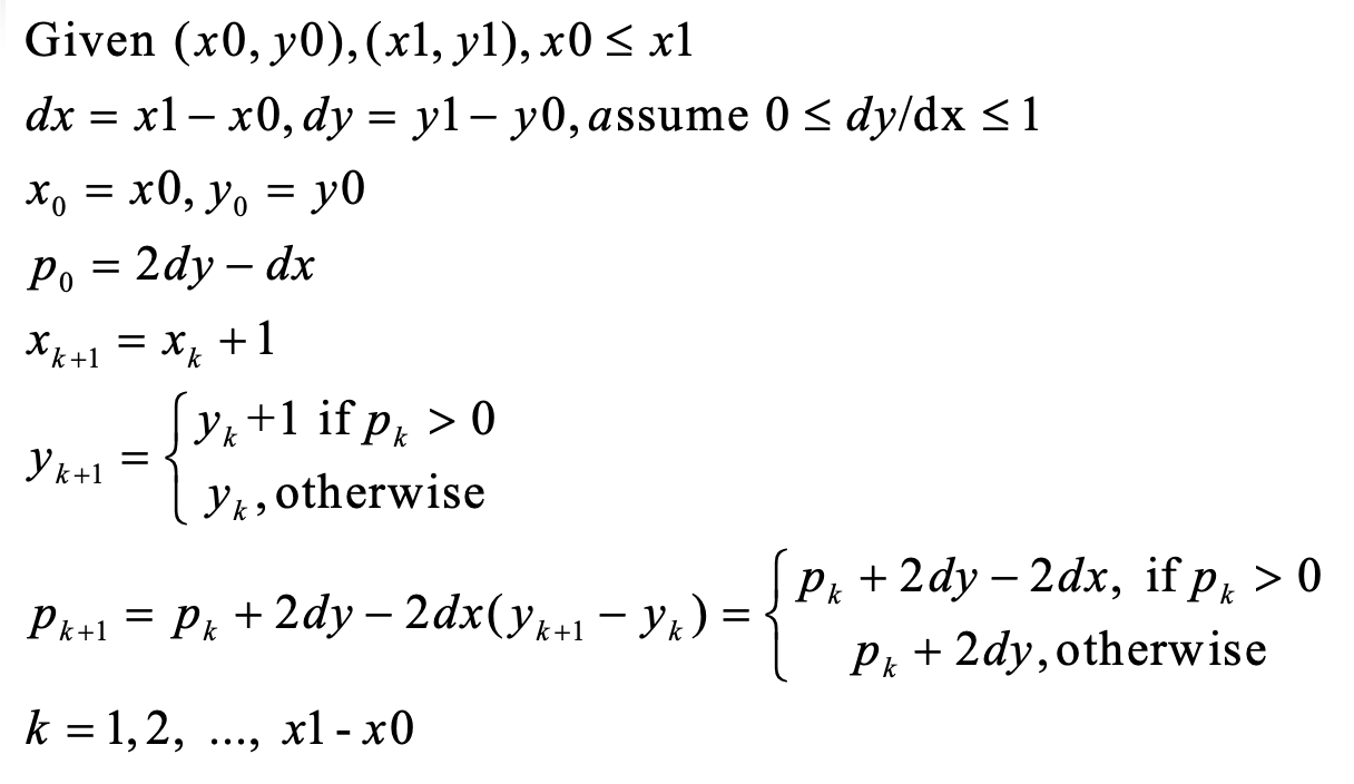
Bresenham Algorithm
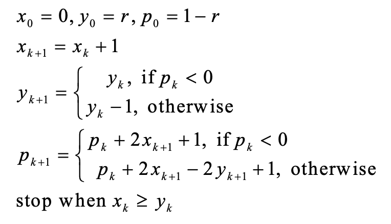
Midpoint Algorithm for Circles
Scan Conversion for Triangles
Edge-Walking Algorithm
Use edge pairs to determine the pixels inside the triangle:
Determine the top point P0, bottom point P2 and break point P1. Walk down pixels from P0 to P1 from each pixel to pixel on P0P2
Fill in horizontal spans for each scan line
Interpolate colours down edges
Pros: fast by using incremental algorithm
Cons: many special cases, not a simple algorithm
Edge Equation
Equation of a line containing the edge, it’s a linear equation of the form: Ax + By + C = 0.
Given a point on the plane, if Ax + By + C = 0 the point is on the edge. If it is positive, then the point is to the right of the edge. If it is negative, then the point is to the left of the edge.
Edge Equation Algorithm
Use edge equations to determine if a pixel in the bounding box is inside the triangle.
Compute the bounding box of a triangle
For each pixel inside the bounding box, set the pixel colour is the three edge equations are greater than zero
Barycentric Coordinates
Use barycentric coordinates to determine if a pixel in a bounding box is inside the triangle given three points not on the same line
Compute the bounding box of the triangle
For each pixel in the box, compute its barycentric coordinates (a, B, y). If all are positive, create a fragment
All fragments are further processed parallel by GPU, writing pixel colour and depth to frame buffer
Rendering General Polygons
Done by decomposing the polygons into a collection of triangles, then rendering the triangles. The two main methods are the triangle fan or triangle strip.
Graphics File Formats
Two main methods of storing images in a file: geometric (vector file format, e.g. SVG, PDF) or raster (raster file format, e.g. BMP, JPG)
2D Transformations
Basic 2D Transformation
Basic transformations are primitive transformations, used to build other transformations by compositing a sequence of basic transformations (translation, rotation, scaling)
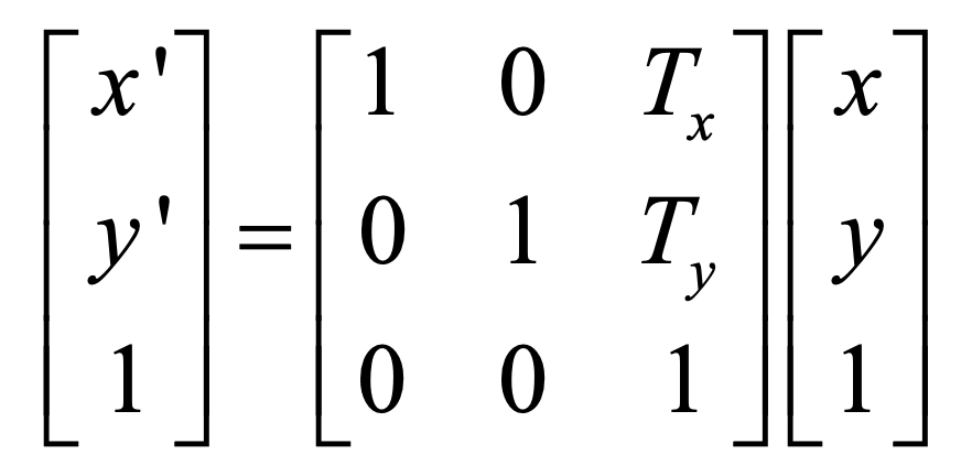
2D Translations
Moves a vertex to a new position by adding a displacement vector (translate vector).
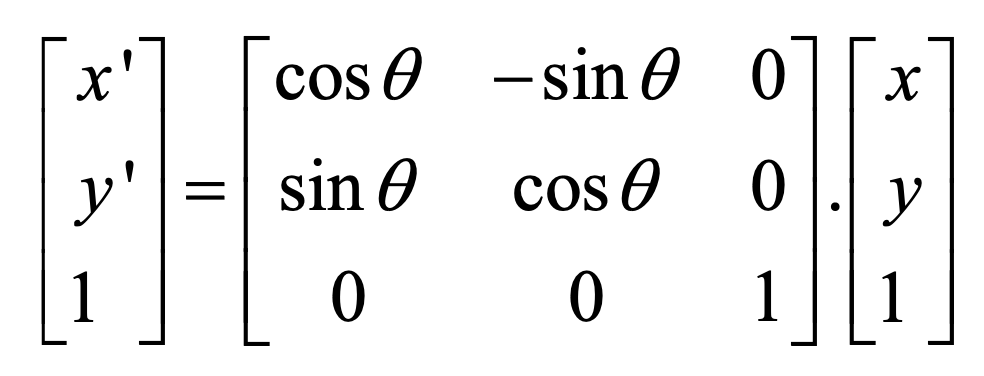
2D Rotations
Rotates a vertex anti-clockwise theta degrees with respect to the origin
2D Scalings
Transforms a vector by multiplying by a scaling factor

Composite Transformations
A sequence of transformations. The formula used gets bigger as the sequence gets longer
Homogenous Coordinates
Adds a new dimension. A point in homogenous coordinates (x,y,w) where is non zero corresponds to the 2D vertex (x/w, y/w) in Cartesian coordinates. The Cartesian coordinates axes lies on the plane of w=1.
Unifying Point and Vector Representations
(x, y, 1) - a point (x, y) in Cartesian coordinates
(x, y, 0) - a vector (x, y) in Cartesian coordinates
Composite Transformations in Homogenous System
In homogenous coordinate systems, each basic transformation is represented in the form of transformation matrices multiplying coordinate vectors. Then the transformation matrix of a composite transformation can be derived by the multiplications of the sequence of transformation matrices of its basic transformations. We then apply this matrix to all vertices to get the transformed vertices
Advantages of using composite transformation matrix
It is more efficient since matrix multiplication is associative, so we can compute the transformation matrix M in advance to save on computing time, and it only needs to store M which saves on memory.
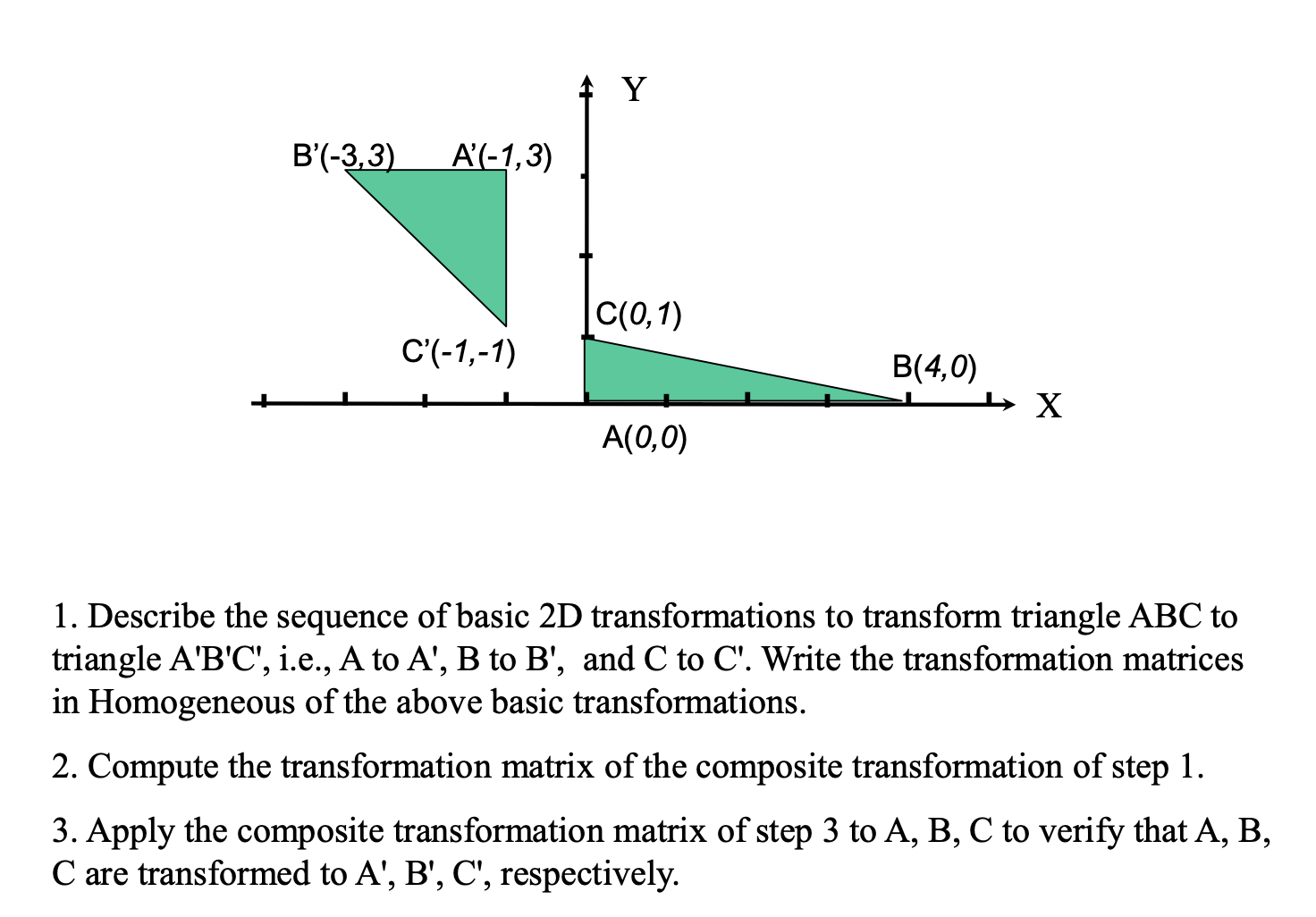
S(0.5, 2), R(180), T(-1, 3)
TRS
A’ = [-1 , 3, 1]’, B’ = [-3, 3, 1]’, C’ = [-1, 1,1]’
Viewing, Projection, Clipping
Clipping
Any procedure that identifies those portions of a primitive that are either inside or outside of a specified region of space. There are several algorithms depending on the primitive type (point, line segment or polygon clipping)
Point Clipping
Given a clipping window position in WCS defined by (LRBT), a point P=(x,y) is within the clipping window is two inequalities are satisfied:
left <= x <= right
bottom <= y <= top
Line Clipping
Render a portion of a line segment that falls in the clipping window. There are four possible relationships between the line and the window:
Totally in (fully contained)
Totally out (does not meet the window at all)
In and out (line starts in the window but ends outside)
Out and out (line starts and ends outside the window, but passes through it at some point)
Cohen-Sutherland Algorithm
Divides the view plane into 9 coded regions by the relations of P(x,y) with the clipping window
Polygon Clipping
Clipping the edges one after another to determine the portion of the polygon inside the clipping window
Object Modelling and Representation
Object Modelling
Mathematical representation of 2D/3D objects
Normal of a Plane
Vector perpendicular to the plane. If a plane is defined by Ax+By+Cz+D=0, then (A,B,C) and (-A, -B, -C) are normals.
Two vectors are perpendicular iff their dot-product is 0.
Calculating a Normal of a Plane
If a Plane is defined by P1, P2, P3, then the Normal is:
(P2-P1)X(P3-P1)
Polygon Modeling
A polygon is determined by a sequence of vertices on a plane. The half space containing the object is inside the surface, the other half is the outside (which we represent using the normal of the plane)
Polygonal Meshes
Collection of polygons that approximate the surface of a 3D object
Why use polygons?
Easy to represent by a sequence of vertices and easy to transform
Simple properties (single normal, well-defined inside/outside)
Easy to draw using polygon-line, polygon-fill or mapping texture routines
Why use a polygon mesh?
A mesh approximates the surface to any degree of accuracy by making the mesh finer or coarser, and can model both solid shapes (polygonal faces fit together without spaces) and thin skins (spaces between polygons)
Properties of Meshes
closed meshes represents a solid object (encloses a volume)
if there is an unbroken path along the edges of the mesh between any two vertices, the mesh is connected
a mesh is simple if it has no holes
a mesh is planar if every face is a plan polygon
a mesh is convex if the line connecting any two interior points is entirely inside the mesh
thin-skin meshes represent non-solid objects
some meshes are not possible irl but can still be rendered
Polyhedron
Connected mesh of simple planar polygons that encloses a finite volume.
every edge is shared by exactly two faces
At least 3 edges meet at every vertex
faces to not interpenetrate
Euler’s formula: V + F - E = 2
Regular Polyhedrons
All the faces are of the same number of vertices, and each is a regular polygon (same length of edge, and same angle by each consecutive pairs of edges). There are only five regular polytopes
Prism
Formed by moving a regular polygon along a straight line. When the line is perpendicular to the polygon, the prism is a right-prism
Culling (Hidden Surface Removal)
Culling
Determining which polygon or parts of polygons are visible from the eye position. There exists two major methods:
object-space (computing at the primitive level)
image-space (computing at the pixel level)
Important Metrics Visibility Computing
Accuracy: result should look right and behave well when chasing eye positions
Complexity: should reduce the complexity by focusing on few primitives
Efficiency: object-space method is fast while image-space method is slow
Factors that Affect Visibility
Direction of a polygon face (if it’s facing away from eye it is not seen)
Distance from a point to the eye
Pixels with smaller depth should cover pixels with larger depth
Distance Between Points
Measured by Euclidean distance
Depth of a Point
Distance between the point and the eye position
Depth of a Primitive
Distance between the eye and the centre of the primitive
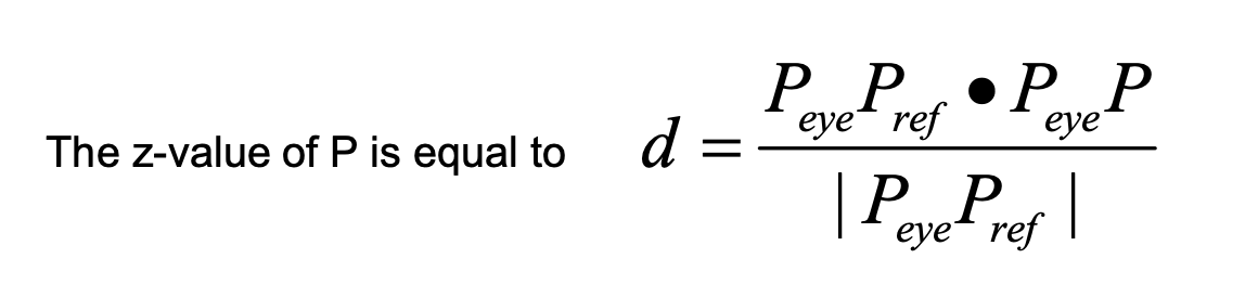
Depth of a Polygon
The z-value of view in coordinate system, which is equal to the length of the projection PeP on PePr
Computing the Z-Value