Cisco Packet Tracer with complete verified solutions already graded A+
1/32
There's no tags or description
Looks like no tags are added yet.
Name | Mastery | Learn | Test | Matching | Spaced |
|---|
No study sessions yet.
33 Terms
Cisco 1841
This is an Integrated Service Router (ISR) having two Fast Ethernet ports, two slots for High Speed WAN Interface Cards (HWICs), and one slot for Advanced Integration Module (AIM)
Cisco 1941
This is similar to the previous model but runs on Cisco IOS Version 15. It has two ports that operate at Gigabit Ethernet speeds. Cisco 2621XM: This is similar to the previous model, except that
Cisco 2620XM
This is a multiservice router with one Fast Ethernet port, two slots for WAN Interface cards, and one slot for AIM.
Cisco 2621 XM
This is similar to the Cisco 2620, except thatthis router has two Fast Ethernet ports.
Cisco 2811
This ISR comes with two Fast Ethernet ports, four WIC slots, and a dual slot for AIM.
Cisco 2901
This router has two Gigabit Ethernet ports, four WIC slots, and two Digital Signal Processor (DSP) slots. This router uses Cisco IOS Version 15
Cisco 2911
This router has three Gigabit Ethernet ports and all the other features of the previous router. It runs on IOS Version 15. G: This is a custom router running on Cisco IOS. It contains 10 slots and has separate modules with a naming convention beginning with PT.
Generic Router-PT
This is a custom router running on Cisco IOS. It contains 10 slots and has separate modules with a naming convention beginning with PT.
A switch, also called a multiport bridge, connects more than two end devices together. Each switch port is a collision domain. The following switches are available in Packet Tracer: Cisco 2950-24: This managed switch comes with 24 Fast Ethernet ports. Cisco 2950T-24: This switch is a member of the Catalyst 2590 Intelligent Switch family and has two Gigabit Ethernet ports in addition to the 24 Fast Ethernet ports. Cisco 2960-24TT: This is another 24 port switch; the previous switch has Gigabit Interface Converter (GBIC) for Gigabit Ethernet ports, whereas this switch has Small Form-factor Pluggable (SFP) modules for the same. Note that this is a difference only on real switches, it has no impact on Packet Tracer. Cisco 3560-24PS: This switch is different from the others because it is a layer 3 switch that can be used to perform routing in addition to switching. The PS suffix implies support for Power over Ethernet (PoE), which can be used to power up IP phones without using power adapters. Bridge PT: This is a device used to segment a network and it has only two ports (which is why it is a bridge; if it had more, it'd be called a switch). Generic Switch PT: This is a Packet-Tracer-designed switch running on Cisco IOS. This is the only customizable switch with 10 slots and several modules. Like the generic router, the switch section also includes a generic switch with 10 slots that can be customized with the required modules. Except for the generic switch, other Cisco modelswitches cannot be customized and do not have a power switch. This is because that is how real switches of the same models are designed.
Accessing the CLI The Command-line Interface of a device in Packet Tracer can be accessed in two ways: The CLI tab Console port Although it is possible to access a device through SSH or Telnet, these are Cisco methods and are not exclusive to Packet Tracer. The CLI tab This is the simplest way of accessing the Command-line Interface of a device; click on a network device, navigate to the CLI tab, and you'll see the booting process. The Console port There is no difference between what is seen and controlled in this method and the previous one, but the Console Port can be used to make the topology look similar to the real world. Follow the steps to configure the console port: Add a PC or a laptop to the workspace. Choose connections, and then click on the console cable. Connect the console cable of the network device to the RS-232 port of the PC/laptop. Open the PC/laptop, navigate to the Desktop tab, open Terminal, and then with the default settings, click on OK to view the console. The following screenshot displays a router's console through its terminal: In step 2, if you use the Automatically Choose Connection Type option, the Ethernet ports of both of the devices will be connected. Configuring network devices In this section, you'll learn how to configure Cisco routers and switches without using a single command! Yes, it is possible; Packet Tracer provides a Config tab that contains GUI options for the most common configurations. What's more, as you tinker with the GUI, its equivalent Cisco IOS command is also displayed. Take a look at the following screenshot: From the Config tab of the switch, we will set the Interface option to FastEthernet0/1 and uncheck the On checkbox for Port Status. So the Equivalent IOS Commands section displays the following command to achieve this process: Switch>enable
Switch#configure terminal
Switch(config)#interface FastEthernet0/1
Switch(config-if)#shutdown
Using the Config tab, the following can be configured: Global settings Routing (on a router and a layer 3 switch) VLAN database (on a switch) Interface settings Let's see what options are offered under each of these sections. Global settings The first part of Global settings allows you to change the Display name and Hostname of the device. The display name can also be changed by clicking on the name below the device icon. The configuration file for the device can also be saved, erased, or exported for later use. The Algorithm Settings section contains settings meant for advanced users who want to minutely tweak their device to see how it responds to certain situations. These settings can also be globally set for all network devices by navigating to Options | Algorithm Settings, or by using the shortcut Ctrl + Shift + M. Routing This section has options for configuring Static and dynamic routing (RIP). To configure static routing, enter the network address, netmask, and its next hop address, and then click on Add. Here is some sample network information: Network: 192.168.30.0 Mask: 255.255.255.0 Next Hop: 10.0.0.6 To configure Routing Information Protocol (RIP), it is enough to add only the network IP. Please note that the GUI uses RIP Version 1, so classless routing is not supported. Routing will be discussed in detail in Chapter 6, Configuring Routing with the CLI. Apart from routers, routing can also be configured on the 3560-24PS switch, as it is a layer 3 switch. The VLAN Database This section will teach you how to create and remove VLANs. VLANs and trunking are discussed in Chapter 10, Configuring VLANs and Trunks. Only the VLAN database can be modified from these options; adding interfaces to these VLANs is what we'll see in the next section. Interface settings This section slightly differs from the switch and the router. Switches have options for modifying the speed and duplex setting and for assigning a port to VLAN. On routers, the VLAN section is replaced by the IP address configuration. While changing the speed and duplex settings, if you are setting it to anything other than auto, make sure that the settings are the same on both ends. For example, if you set it to 100 MBps on one end and 10 MBps on the other, the link won't come up. Summary In this chapter, we learned a lot about network hardware devices and their modules, along with each one's features, limitations, and their naming convention. We have also seen the methods through which the CLI can be accessed. By now, you will have been able to configure these devices with just the GUI. If you are the adventurous kind, go ahead and try creating a simple topology with a couple of routers and PCs residing in different logical networks.
True or False: PC s have a lot of utilities under the Desktop tab that match the ones you have on your real computer!
True
Desktops and Laptops
Desktops and laptops Desktops and laptops form the highest level of configurable and usable client devices in Packet Tracer. There is no difference between them when it comes to usability; only the naming conventions of the modules are different. The following modules are available for desktops and laptops. Similar to routers (as seen in the previous chapter), these devices too have to be switched off before adding/removing modules. Linksys-WMP300N: This provides a wireless interface for configuring WLAN on a WiFi network. PC-HOST-NM-1AM: This provides an RJ11 interface that can be used as a dial-up modem. PC-HOST-NM-1CE, PC-HOST-NM-1CFE, PC-HOST-NM-1CGE: These three modules provide an Ethernet, FastEthernet, and GigabitEthernet connection, respectively. PC-HOST-NM-1FFE, PC-HOST-NM-1FGE: This is the fiber Ethernet version of the previous module. PC-HOST-NM-1W, PC-HOST-NM-1W-A: Both of these modules provide a wireless interface for WLAN. The first one has a frequency of 2.4 GHz and the second 5GHz for 802.11a networks. PC-HEADPHONE, PC-MICROPHONE, PC-CAMERA, PC-USB-HARD-DRIVE: These modules serve the purpose of representing each of their respective devices. They do not have any functionality associated with them. On laptops, the same modules are available with a different name. Instead of HOST, LAPTOP is used. So, a PC-HOST-NM-1AM module is named PC-LAPTOP-NM-1AM.
Servers
Servers Servers are an entirely different breed when compared to other end devices. They have various functionalities and also have space for two network interfaces. The modules available for servers are the same as PC modules, except that the servers do not have the PC-HOST-NM-1AM module. Looking under the Config tab of a server, you can see that the following services are available. Let us look at what each of these offers. HTTP The HTTP service offers a web server that runs both HTTP and HTTPS protocols. A textbox below the HTTP section provides options to create and edit static HTML pages. These are displayed when this server is accessed through the web browser utility of other end devices. This service is on by default. DHCP The DHCP service can be used to assign IP addresses to routers. This section has options to create and edit DHCP pools of IP addresses. It has a default pool called serverPool, which cannot be removed or edited. This service is off by default. TFTP The TFTP service can be immensely useful when learning about backing up and restoring Cisco IOS images and configuration files. This section lists several IOS images from routers and switches available in Packet Tracer. If any file is copied from a network device to the TFTP server, that too will be displayed. A sample is available at Cisco Packet Tracer 6.0.1\saves\Server\TFTP\TFTP.pkt. This service is on by default. DNS The DNS service is for resolving domain names to IP addresses. The DNS service offers the following record types: A, CNAME, SOA, and NS. Though this interface looks simple and complete, multilevel DNS setups can be configured. A sample is available at Cisco Packet Tracer 6.0.1\saves\Server\DNS\Multilevel_DNS.pkt. A DNS cache button allows you to view cached DNS requests and has a feature that clears this cache. This service is off by default. SYSLOG This protocol provides a centralized logging service. Setting the Syslog server's IP to point to the configured server's IP from a network device fills the table in the Config tab with all of the logging messages generated by the device. This service is on by default. AAA AAA stands for Authentication, Authorization, and Accounting. This service is used for centrally managing the credentials of all network devices. It supports the RADIUS and TACACS authentication protocols. The options in this section allow you to create users and configure the network credentials to be used. Several samples are available at Cisco Packet Tracer 6.0.1\saves\Server\AAA\. This service is off by default. NTP Network Time Protocol ensures that the clocks of all devices are synchronized properly. This section has a calendar to set the date and time. Optionally, NTP authentication can also be configured. Once the server has a proper time set, all of the network devices can be configured to synchronize their clocks from this server. This service is on by default. EMAIL This section incorporates SMTP service and POP3 service. A domain name can be set and users created so that users can communicate by using the EMAIL option under the Config tab of a PC or laptop. Only one domain is allowed per server, and either SMTP or POP3 can be switched on or off as desired. FTP FTP has more features as compared to TFTP. Users can be created and permissions can be granted to each one of them. This section also lists files that have been uploaded. There is no GUI client for accessing the FTP server. But the command line under the Desktop tab provides the FTP command-line client. A sample is available at Cisco Packet Tracer 6.0.1\saves\Server\FTP\FTP.pkt. Firewall/IPv6 Firewall Because the server has two network interfaces now, the firewall feature has been introduced in PT Version 6. This section allows you to configure inbound rules that match source/destination IP addresses and local/remote port numbers. Based on the match, the connection can either be allowed or denied.
Creating a simple topology
Creating a simple topology Now that you're familiar with the GUI of Packet Tracer, you can create your first network topology by carrying out the following steps: From the network component box, click on End Devices and drag-and-drop a Generic PC icon and a Generic laptop icon into the Workspace. Click on Connections, then click on Copper Cross-Over, then on PC0, and select FastEthernet. After this, click on Laptop0 and select FastEthernet. The link status LED should show up in green, indicating that the link is up. Click on the PC, go to the Desktop tab, click on IP Configuration, and enter an IP address and subnet mask. In this topology, the default gateway and DNS server information is not needed as there are only two end devices in the network. Close the window, open the laptop, and assign an IP address to it in the same way. Make sure that both of the IP addresses are in the same subnet. We'll be learning more about end device configuration in Chapter 3, Generic IP End Devices. Close the IP Configuration box, open the command prompt, and ping the IP address of the device at the end to check connectivity. Pinging Laptop0 from PC0 What is a network topology without a single network device in it? Add an Ethernet switch to this topology so that more than two end devices can be connected, by performing the following steps: Click on Switches from the device-type selection box and insert any switch (except Switch-PT-Empty) into the workspace. Remove the link between the PC and the laptop using the delete tool from the common tools bar. Choose the Copper Straight-Through cable and connect the PC and laptop with the switch. At this point, the link indicators on the switch are orange in color because the switchports are undergoing the listening and learning states of the Spanning Tree Protocol (STP). Once the link turns green, as shown in the previous screenshot, ping again to check the connectivity. The next chapter, Chapter 2, Network Devices, will deal with the configuration of network devices. To save this topology, navigate to File | Save As and choose a location. The topology will be saved with a .pkt extension, with the devices in the same state.
A, Jesin. Packet Tracer Network Simulator (Professional Expertise Distilled) . Packt Publishing. Kindle Edition.
Console
This is a console cable that is used to view the network device's console from a PC/laptop. One end of the cable connects to the console port of a network device while the other one connects to the RS-232 port on a PC/laptop.
Copper straight-through:
This is a standard Ethernet cable that is used to connect two devices that operate in different layers of the OSI model (such as hub to router and switch to PC). It can be used with Ethernet, Fast Ethernet and Gigabit Ethernet port types..
Copper cross-over:
This Ethernet cable connects devices operating in the same OSI layer (such as hub to hub, PC to PC, PC to router, and PC to printer). This cable can also be used with Ethernet, Fast Ethernet and Gigabit Ethernet port types.
Fiber Cable
This cable connects Fast Ethernet and Gigabit Ethernet ports of a fiber port.
Phone Cable Connection
This RJ11 cable connects the analog phone to a VoIP phone or a PC's modem to a cloud. It also connects the modem interface of routers.
Coaxial Cable Connection
The coaxial cable connects the cloud with a cable modem and a TV with the cloud.
Serial DCE and DTE
Serial cables connect routers together and connect routers to the cloud. The DCE (Data Circuit-terminating Equipment) end has a clock symbol on it. Clocking must be enabled on this end using the clock rate <300-4000000> command to bring the line protocol up. If Serial DTE (Data Terminal Equipment) is chosen, the first device connected with this cable will be the DTE end and next device will be the DCE end. For the Serial DCE cable, this is just the opposite.
Automatically choose connection type:
If you are confused about the cable to use, choosing this option automatically connects two devices with the best cable. We say best cable because if you have two routers with serial and Fast Ethernet interfaces on both of them and want to connect both of their Fast Ethernet interfaces, choosing this option will connect only their serial interfaces together. Similarly, console ports cannot be connected using this option.
Octal:
This cable was introduced in PT Version 6. It has a high-density connector on one end and eight RJ45 plugs on the other.
What connection cable do you use to setup like cable connections?
Copper cross-over: cable
What's another name for FastEtherne0/1
Fa 0/1
What's another name for FastEtherne0/2
Fa 0/2
True or False you need to open port status on Router to to make connect to switch
True
Static Routing
The methos for configuring routing. With Packet Tracer, statci routing can be configured using GUI. In this method we configuer a router with a destination and a gateway to reach it
Click on a router icon, got o th Config tab select an innterface, and configure the IP address. Make sure I select the On checkbox in this section to bring the port state up.
Step 2 of assigning IP address to Router
Under the ROUTING section, click STATIC.
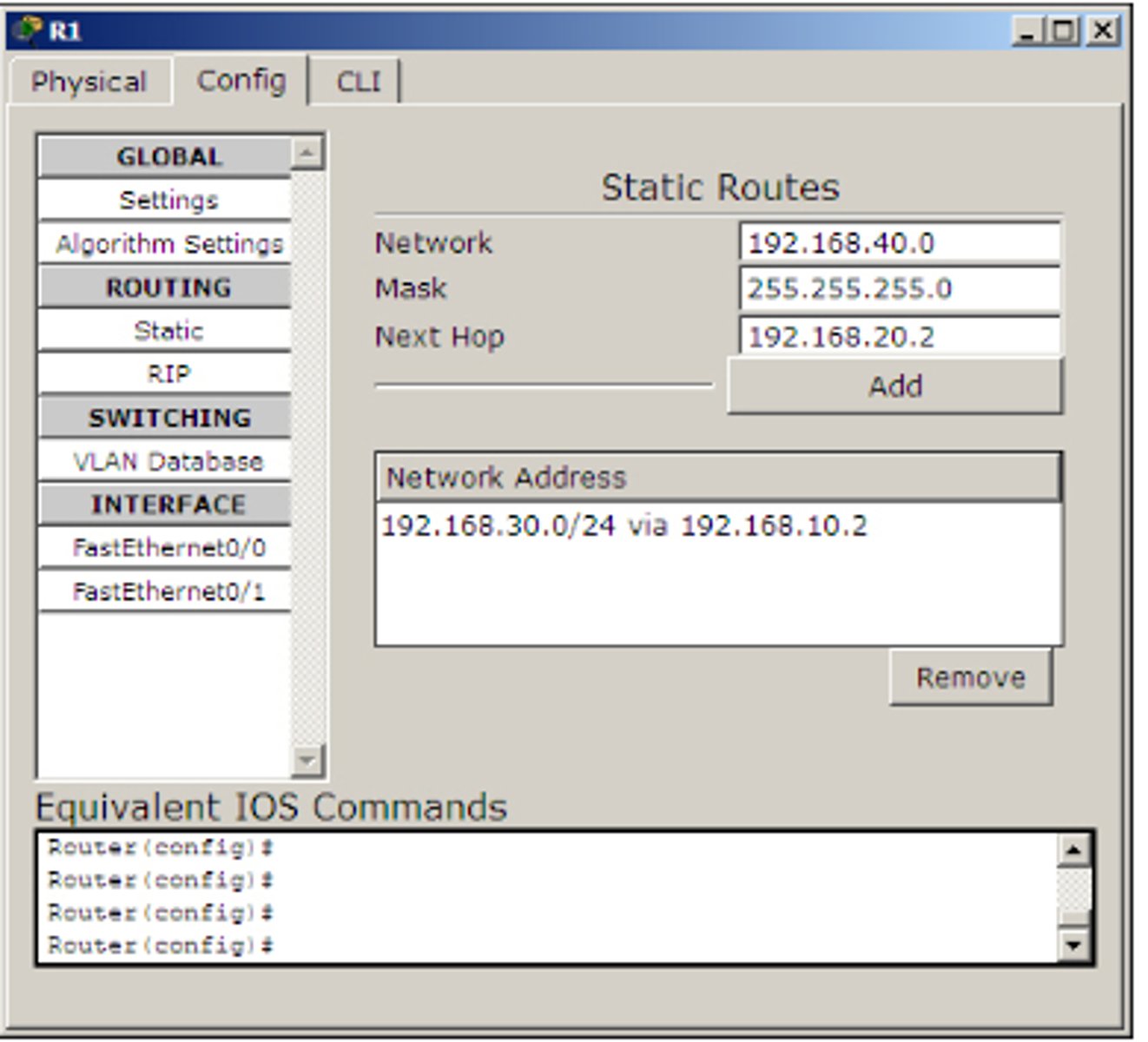
Generally what is the mask(subnet mask for router)
255.255.255.0
Step 3 to of assigning IP address to Router
Use simple PDU and test the connectivity between the router. Then use the simulation mode to find the route taken by the packets
Stating Routing with the CLI
of assigning IP address to Router