Control Systems - My Latest Edit
1/17
Earn XP
Description and Tags
Name | Mastery | Learn | Test | Matching | Spaced | Call with Kai |
|---|
No analytics yet
Send a link to your students to track their progress
18 Terms
Plant
Component/Factor you want to control
Sensor
Detects change in factor
Controller
Adjusts the signal to the plant
Setpoint
Desired value, compared to measured value
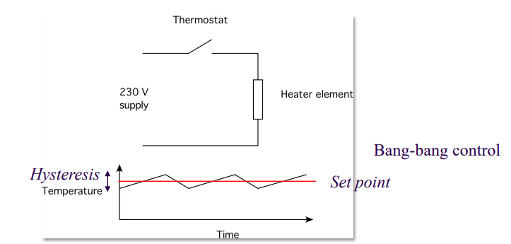
Hysteresis
The difference between the measured value and the setpoint value.
{Essentially shows that the actual change lags behind the desired ideal change}
Laplace operator
s = jω
Operations in the s domain
Change in Time domain ≡ Equivalent change s domain
Integrating by dt ≡ multiplying by 1/s
Differentiating by dt ≡ multiplying by s
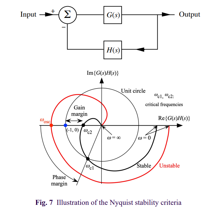
Single-Loop feedback system
Fraction of output signal (Vo) is measured and subtracted from the input signal (Vi) to create an error signal (Ve).
Ve = Vi - kVo → where k is a fraction {determined by the components on the feedback loop}
Open Loop transfer function (OLTF)
No feedback loop connection
OLTF = Forward loop combination
OLTF = G(s)*H(s)
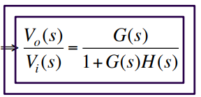
Closed-Loop transfer Function (CLTF)
Vo / Vi = G(s) / (1 + G(s)*H(s))
G(s) is the transformation on the forward loop
H(s) is the transformation on the feedback loop
Determining theType of a control system
Determined by the number of poles at the origin in the s domain, in an open-loop transfer function (OLTF)
Also seen as the number of integrators in feedback the system
{Essentially where the denominator of an open-loop trasnfer funtion of a control system = 0, and the number of times where s = 0}
Example:
G(s)H(s) = 1/s(s+1)(s+2) → Type 1
ALWAYS USE OLTF TO DETERMINE TYPE
MUST ALSO BE IN A NEGATIVE UNITY FEEDBACK {H(s) = 1}
Determining the Order of a Control system
The greatest order of power of s in a closed-loop transfer function (CLTF).
{Also can be stated as the total number of poles of a system}
Example:
CL(s) = G(s)/ (1+G(s)H(s)) = 2s/(s2+2s+1)
→ Order of this system is 2 as largest power of s in the denominator is 2.
CLTF [1+G(s)H(s)] or OLTF [G(s)H(s)] can be used
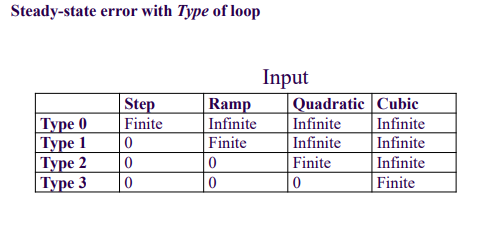
Type Zero Control System
Proportional loop (Kp)
No integrators in control loop
Finite steady-state error (SSE) to a step input
Type I control system
Integral loop
One integrator in control loop
Zero steady-state error (SSE) to step input

Type II control system
Integral Loop
Two integrators in control loop
Zero steady-state error to ramp input
Stability of a control system that can vary with Frequency
Gain margin → Difference in magnitudes of the OLTF of the control system and at unity.
Phase margin → Phase difference of the control system at unity, measured from the negative Real axis on the argand diagram
Type of a system and its SSE to an input
(Notice the pattern regarding type, and finite/infinite SSEs)
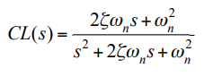
Classic Second order type 2 system
CL(s) = (2ζωns +ωn2) / (s2 + 2ζωn +ωn2)
where ζ is the damping factor