X-ray Imaging System
1/53
There's no tags or description
Looks like no tags are added yet.
Name | Mastery | Learn | Test | Matching | Spaced |
|---|
No study sessions yet.
54 Terms
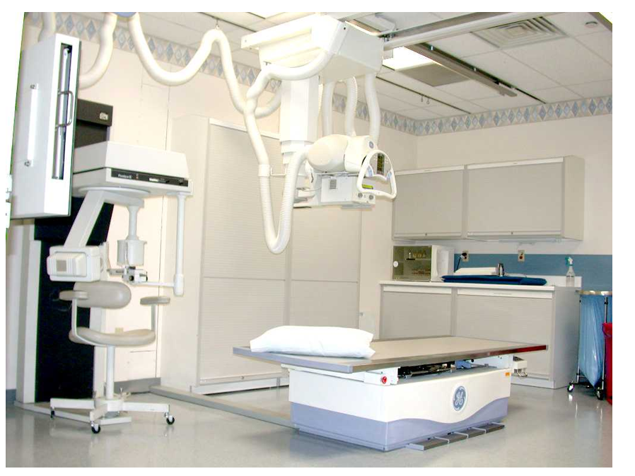
Parts of an X-ray Room
X-ray Tube
Collimator
Shutters (it is in the collimator. It retricts the light field where we are going to aim the x-ray on)
Light field (where the x-ray is gonna go)
Gauges (measure the distance from the tube to the patient)
angles (gauges measure the angles)
field sizes
(both angles and field sizes are the primary ones)
Table (one of the most important part)
carbon fiber (the material that we normally use)
(most table can hold up to 450 to 500 pounds)
floating (type of table we have)
tilting (some people need to be in an upright position)
bucky tray (where we put the cassette or the image receptor)
Windows/door/walls- Lead lined (avoid the radiation leakage to the public)
Console (the machine that we control the amount of x-ray)
(digital, touch screen, icons)
•on/off
•line compensation
•mA (quantity) (how much x-ray being produced)
•automatic timers
•time
•exposure switch (dead man switch)
•kV (quality) (the quality of x-ray is produced and controlled or manipulated by the kV)
•bucky (table v. wall) (primary what we use for standing x-ray)
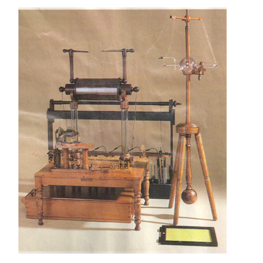
Roentgen’s X-ray Machine
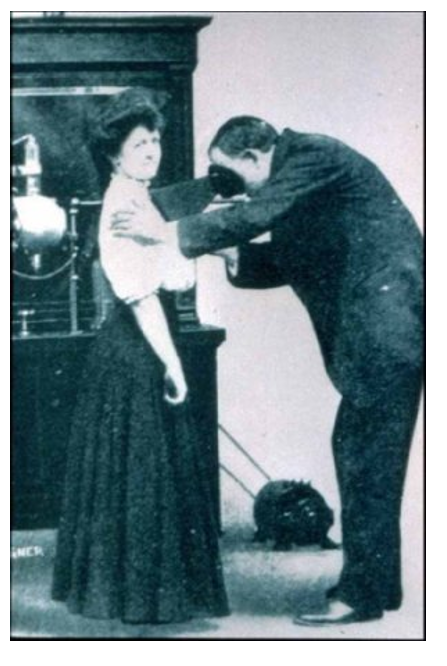
exam on the patient’s heart They have scope because it has to be darkness.
Those are numbers. It will tell the distance of the tube to the bucket itself or to the table or the bucket. It is the one that controls the collimator.
No wire
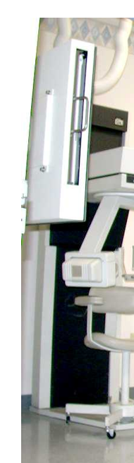
wall bucky. You can pull and put the image receptor in and bring it back. We can put it high and down
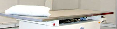
table bucky where you can pull and put the cassette or image receptor

The pedals that can either bring the table up or down, then release the lock so you can float the table
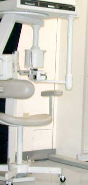
This is panoramic x-ray or panorex. Determine how much damage on their jaw. This is what dental office uses for those who want to have braces
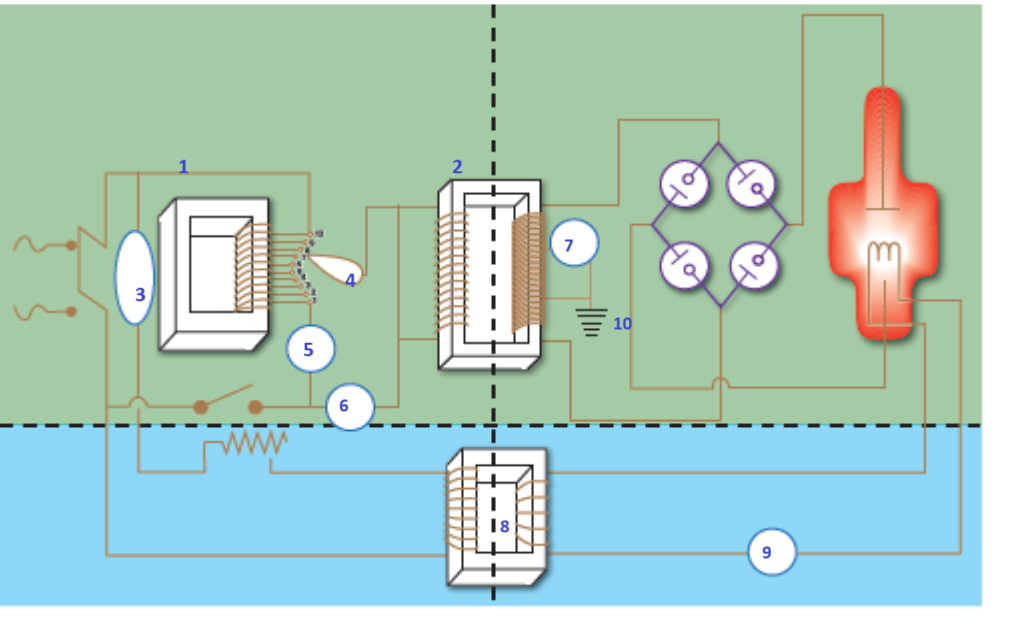
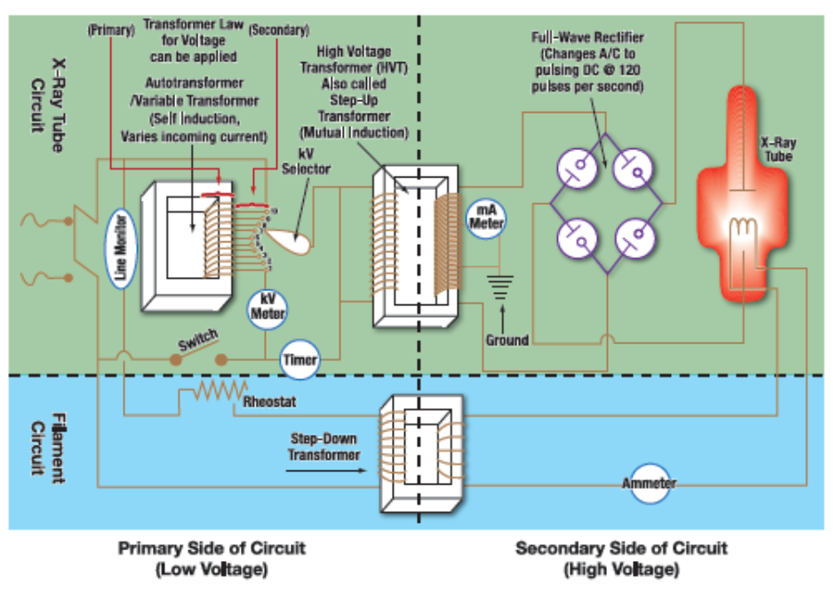
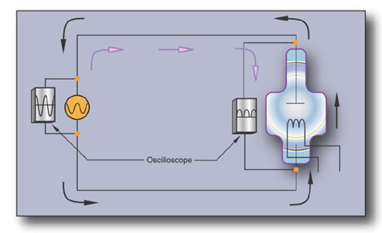
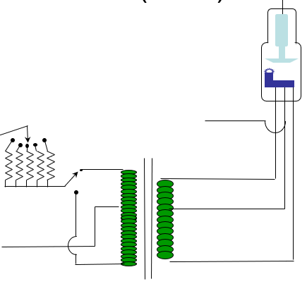
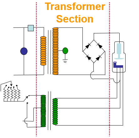
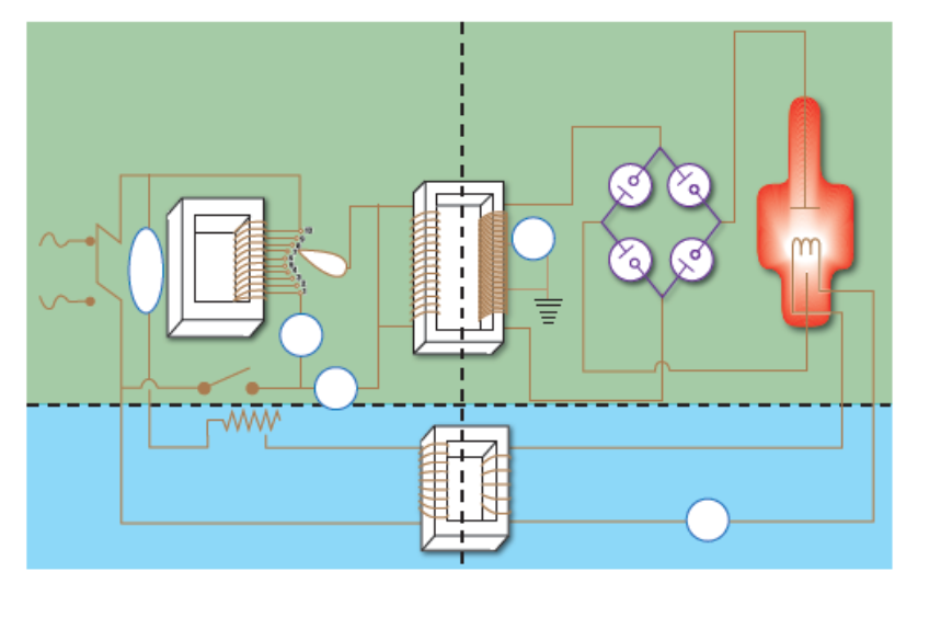
the whole circuitry that is needed to produce x-ray
X-ray tube circuit on the top (red area)
Filament circuit on the bottom (green area)
left side is the primary side which is low voltage
right side is the secondary side of the circuit or high voltage side
Primary side and x-ray tube circuit
line voltage compensator (3) (keeps 220 V go inside the circuit)
autotransformer (1) (self induction produce maximum of 220 volts. This controls the amount of electricity that is going through the x-ray circuit)
kV selector (4) (transfer the voltage all the way to the step up transformer) (from primary side to secondary side, the ratio is 1 to 1000)(turn to kilo voltage)
kV meter (5)
timer (6)
Primary side and secondary side and x-ray tube circuit
step up transformer (2)
Primary side and secondary side and Filament circuit
Step down transformer (8)
secondary side and x-ray tube circuit
mA meter (7)
ground (10) (step up transformer grounded)
Autotransformer
• Variable Transformer
• Operates by self Induction
• Selects a portion of the incoming line
voltage (because kV selector)
– Line Voltage compensator:
• Measures the voltage and adjusts to precisely
220 V
what device measures the voltage and adjust ot or keeps it constant at 220 volts?
Line Voltage compensator
kV Control
• Determines the penetrating quality of the beam
• Primary side of HVT (50 kV - 120 kV max)
• Pre-reading kV meter (it reach how much voltage it will give off to the high voltage transformer)
the higher kV the higher penetrate
mA Control
• Determines the # of e boiled off at filament (thermionic emission)
• Quantity
• Controlled by filament current (3-6A)
• mA meter- secondary side of HVT
mA Meter & Ground
• mA Meter Location
– Secondary side of HVT
• Ground Location
– Secondary side of HVT
– Transformer is grounded
due to the high voltage
– For safety
Exposure Timers
• Allows the e- to flow from cathode to anode for a specific period of time (measure in millisecond)
• Located on primary side of HVT
Mechanical Timers
– Spring action
– Inexpensive
– Inaccurate for times less than 1/20 s
– Used in portable, dental units
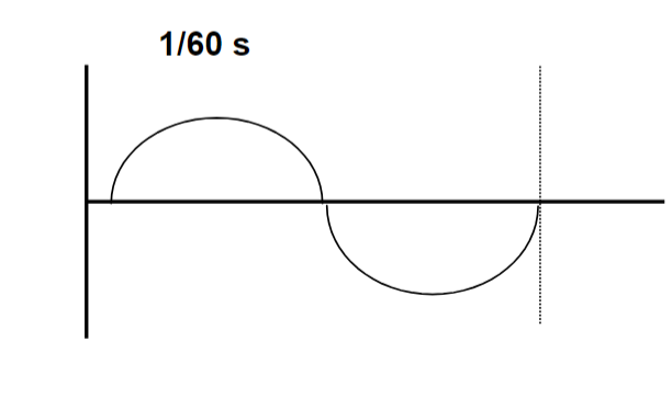
Synchronous Timer
– start/stop with AC cycle
– 60 Hz = 60 start/stop positions
– shortest time = 1/cycle = 1/60 s
1/60 (basic cycle)
• 1/60 + 1/60 = 2/60= 1/30 (2 cycles)
• 1/60 + 1/60 + 1/60 = 3/60 = 1/20
• 1/60 + 1/60 + 1/60 + 1/60 = 4/60 = 1/15 (4 cycles)
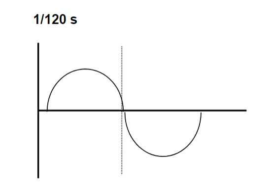
Impulse Timer
– 60 Hz = 120 pulses
– shortest time = 1/pulse = 1/120 s
1/120 s
• 1/120 + 1/120 = 2/120= 1/60 (2 cycles)
• 1/120 + 1/120 + 1/120 = 3/120 = 1/40
• 1/120 + 1/120 + 1/120 + 1/120 = 4/120=1/30 (4 cycles)
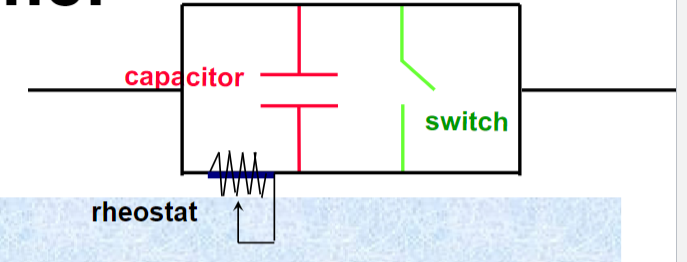
Electronic Timer
Operation:
when a precise voltage is reached in capacitor, the switch opens & terminates the exposure
shortest time = 1 ms = .001 s = 1/1000 s
(electronic timer is not associated with the sine wave)
mAs Timer
Exposure is terminated when desired mAs is attained
– Highest mA, shortest time (avoid motion)
– on secondary side of HV transformer
Timer Comparison
• 1 phase
– mechanical shortest = 1/20 s 250.0 ms
– synchronous motor shortest = 1/60 s 16.6 ms
– impulse shortest = 1/120 s 8.3 ms
• 3 phase
– electronic shortest = 1/1000 s 1.0 ms
(require more electricity)
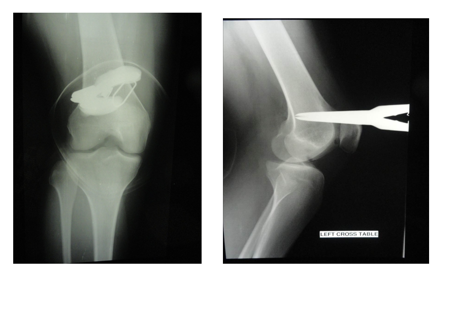
need to take x-ray 2 side
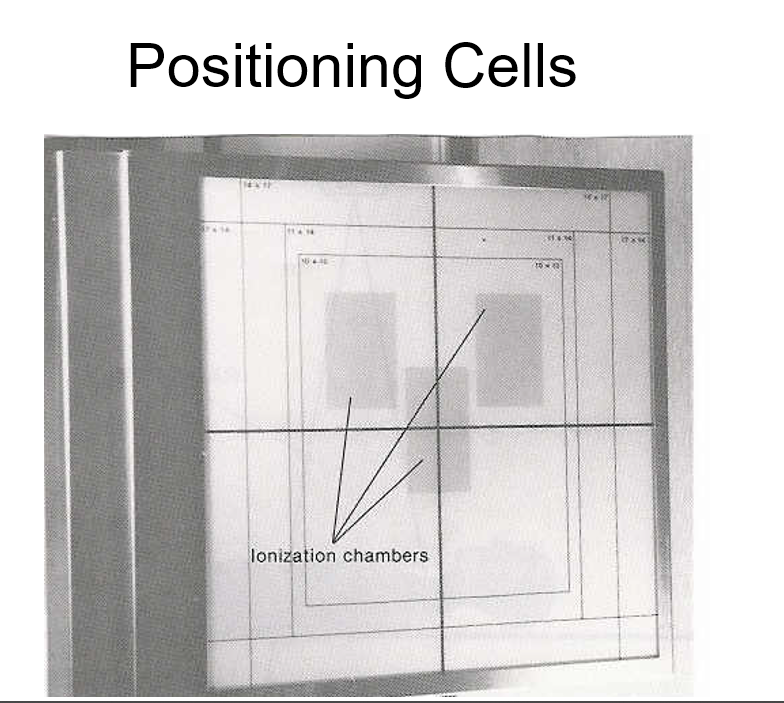
Automatic Exposure Control
(AEC)
– detects radiation that has passed through the patient
– terminates exposure after set amount of radiation reaches sensing device
– based on the ionization caused
(it is not consider timer of machine)
(ionization chamber gains or loss the electrons)
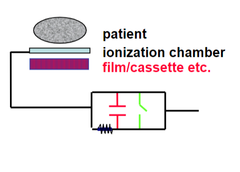
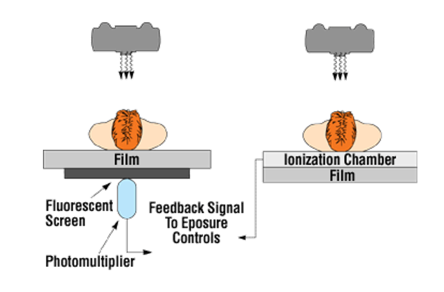
convert radiation into an electrical signal which will be used to automatically stop the exposure when the image receptor has reached the proper density.
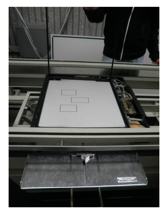
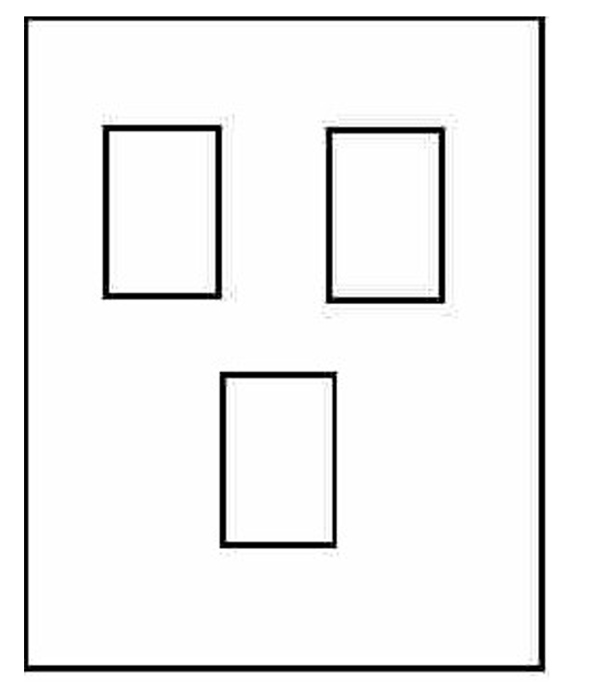
AEC
• Positioning cells
• Back up time
Chest X-ray with a Wall Bucky
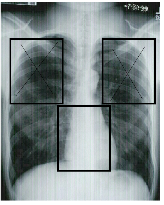
Activate 2 top (ladeside) but not active the bottom because it has a heart.
front to back of patient (AP) (chest x-ray)
back to front (PA)
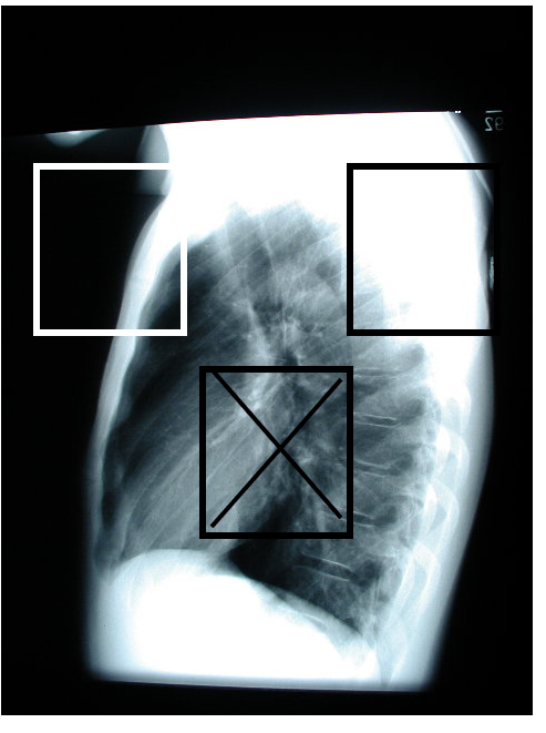
Activate the bottom because it only has one shoulder.
if we activate the left top side, it will under exposure.
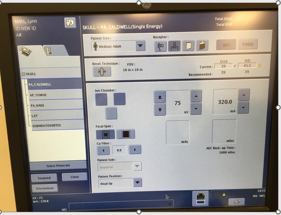
Skull AEC Demonstration
150 mA
60 kV
select the middle part
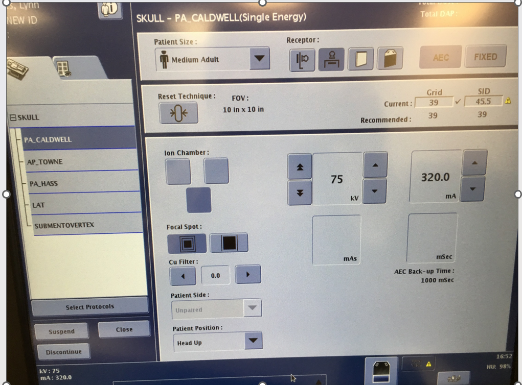
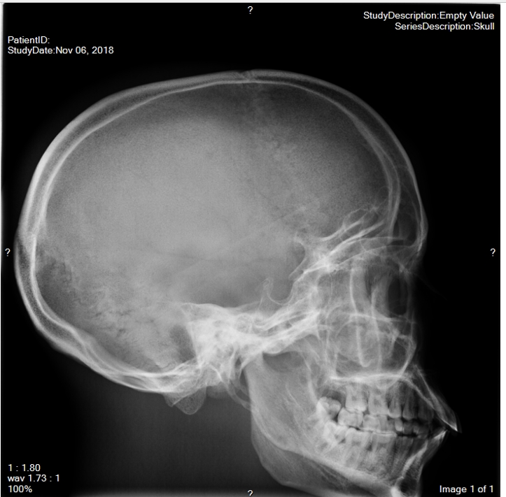
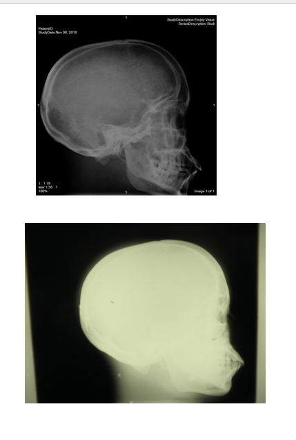
raw image. Right AEC

choice 2 top
the top is better than bottom
bottom is under exposure
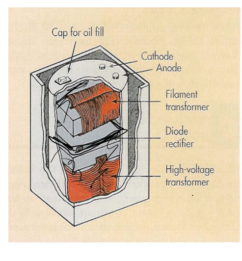
High Voltage Generator
• Contains
– HVT (step up) (high voltage transformer)
– Filament transformer (step down)
– Rectifiers
• Immersed in oil for insulation (reduce the heat)
Rectification
• Purpose
– convert AC to pulsed DC for x-ray tube
• Location
– between HVT & x-ray tube
• Types
– full wave -- most common
– half wave -- limited use
– self -- rarely
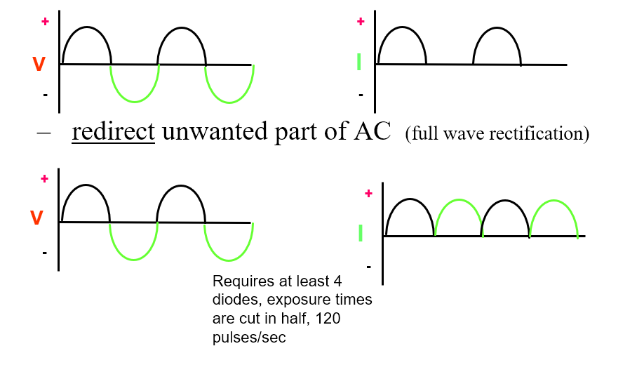
Rectification Process
• Methods
– suppress unwanted part of the AC (half wave rectification)
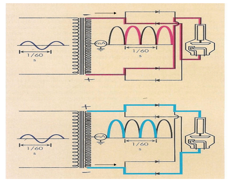
– redirect unwanted part of AC (full wave rectification) (4 exposures)
Requires at least 4 diodes, exposure times are cut in half, 120 pulses/sec
(if half wave require the 120 pulses then full wave require the 60 pulses)
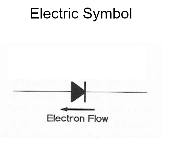
this is diodes rectification
device has positive and negative sign
x-ray tube also the rectification device
electrons flow opposite sign of the tip of the arrow of the diode
Half Wave Rectification
pink arrow can’t pass the diodes
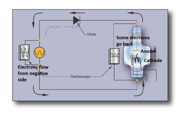
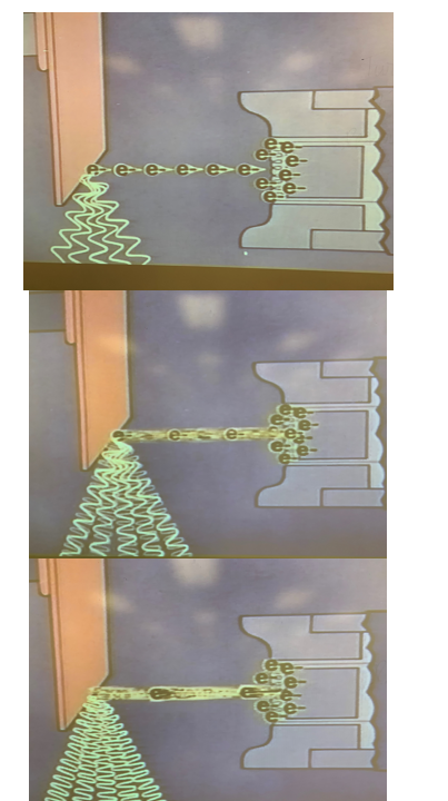
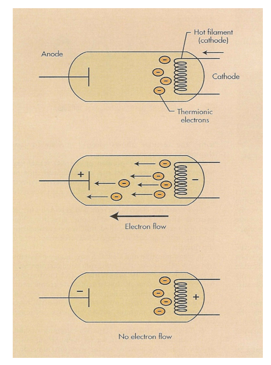
Self Rectification
Produces Half Wave
electrons go from negative to positive then go backward and stop at anode
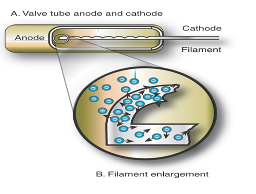
Valve Tubes
• Glass tube
• Filament
• Vacuum tube
Valve Tubes & X-ray Tube (self rectification)
negative current can not go through the anode
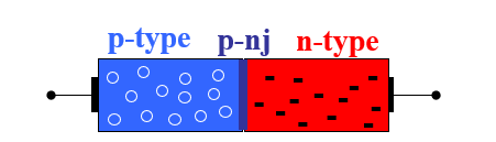
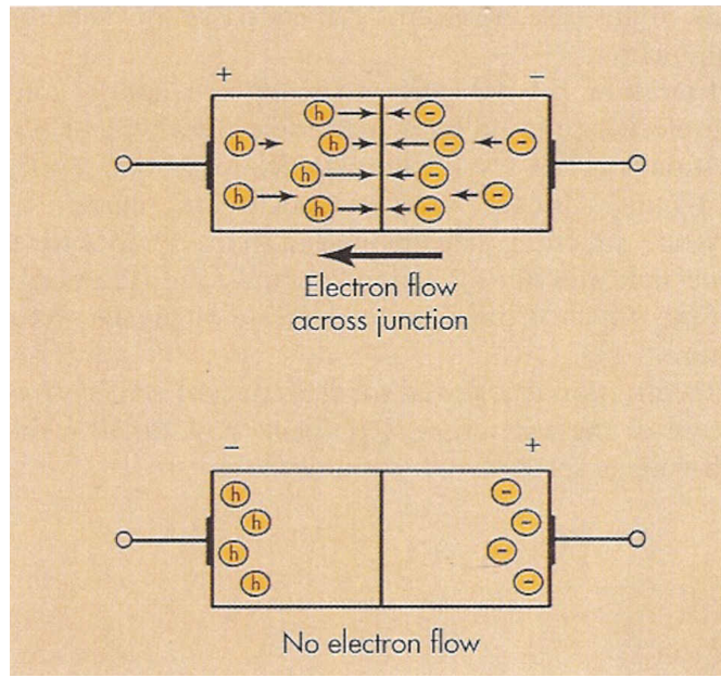
Solid State Rectifier
1) "n-type" material ArseNic (negative) (semiconductor)
2) "p-type" material gallium (p) (positive)
3) p-n junction
– union of the two types of materials
Solid State
• Rugged
• Durable
• Small
Solid State Rectifier
h is the hole that need to be fill during electrons flow
Full-Wave Rectification
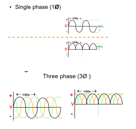
Single vs. Three Phase Power
form AC to rectification
1Ø vs. 3Ø HV Transformers
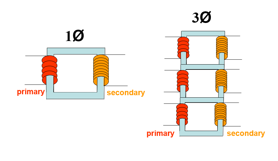
3Ø comparison to 1Ø
• 3Ø more efficient than 1Ø
• 3Ø requires more complex circuitry
• 3Ø more expensive to install
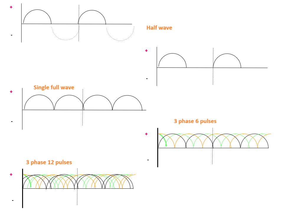
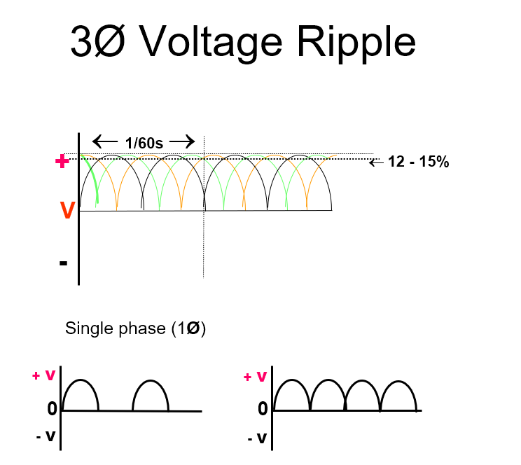
Voltage Ripple
• 100% ripple
– voltage fluctuation in waveform
• Variation in peak voltage waveform
• Single phase- 100% ripple
• 3 phase/6 pulse- 14% ripple
• 3 phase/12 pulse- 4% ripple
• High frequency- 1% ripple
• Less ripple- greater efficiency
• shorter exposure times may be used with 3 phase
Step-Down (Filament Circuit) Transformer
• purpose
– adjust current to cathode filament to produce the heat required for thermionic emission of e-
– control # x rays
Increase IF = increase heat =increase # e- = increase # x rays
(need only 3A to 6A to boilt off electrons from filament)
Operation
– Rheostat
– Choke Coil
– current increase to 3 to 6
A required for thermionic emission boiling off e-
Variable Rheostat
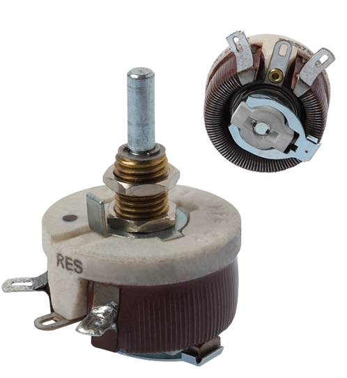
Choke Coils
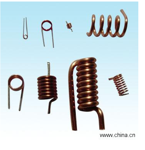
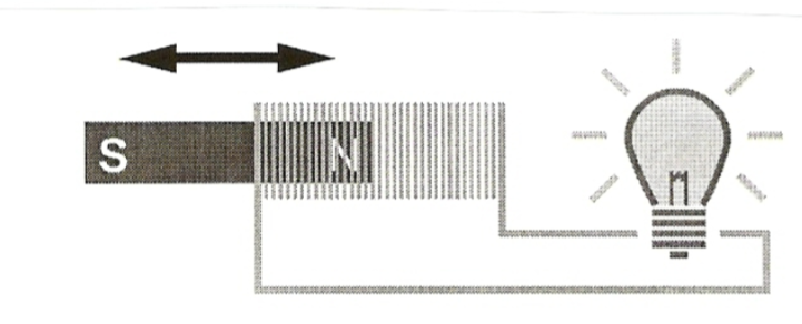
when a magnet moves through a coil (choke coils). induced current flows
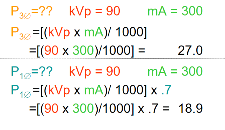
Power Rating
mA X kV = W
(mA X kV) /1000= kW
Single Phase
mA X kV X 0.7
Exposure Power Problem
• An x-ray machine is set for an exposure to use 90 kVp, 300 mA and 0.1 s. What is the power used for this exposure? (3 phase & 1 phase)
tube current measures in mA
fiflament current measures in A