Grade 10 Physics - Optics
1/36
There's no tags or description
Looks like no tags are added yet.
Name | Mastery | Learn | Test | Matching | Spaced |
|---|
No study sessions yet.
37 Terms
An image
a reproduction of an object produced by an optical device like a mirror
An optical device
any technology that uses light
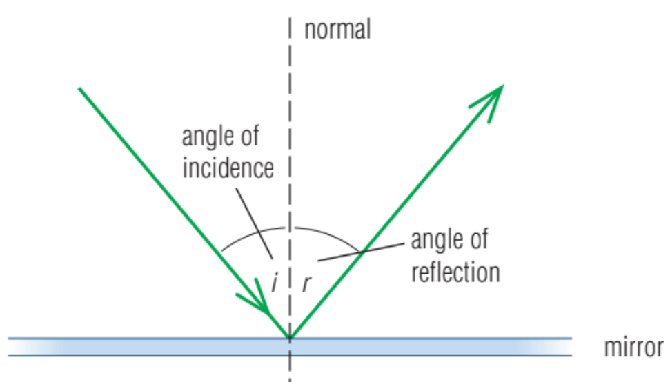
the normal
The dashed line drawn perpendicular to the mirror at the point of reflection
the incident ray
the incoming ray
The angle of incidence
The angle between the incident ray and the normal, labelled i
the angle of reflection
The angle between the reflected ray and the normal, labelled r
the law of reflection
When light reflects off a surface, the angle of incidence is always equal to the angle of reflection.
Written as θi = θr
the reflection of a single ray of light in a ray diagram
a plane mirror
Any mirror that has a flat reflective surface. When you look into a plane mirror, your image appears to be as far behind the mirror as you are in front of it. It is a virtual image.
A virtual image
any image formed by rays that do not actually pass through the location of the image
Types of curved mirrors
Concave (converging) and convex (diverging).
The focal point
The common point where lights rays meet, or appear to meet, in a curved mirror, represented by an F.
Parts of a curved mirror
The middle point of a curved mirror is called the vertex. The principal axis is an imaginary line drawn through the vertex, perpendicular to the surface of the curved mirror. The distance between the vertex and the object is represented by do. The distance between the vertex and the image is di. The height of the object is ho, and the height of the image is hi. The focal length, f, is the distance from the vertex to the focal point of a curved mirror.
A real image
an image formed by light rays that converge at the location of the image. If you place a piece of paper at the spot where a real image forms, a focussed image would appear on the paper or screen.
A concave mirror
also called a converging mirror, has a surface that curves inward like a bowl. If the object is far away from the focal point, the reflected rays form an inverted image. The closer the object gets to the focal point, the larger the image becomes. If the object is between the focal point and the mirror, the image becomes upright, enlarged, and virtual. When the object is exactly at the focal point, all rays that leave the object reverse direction at the mirror and are reflected away from the mirror parallel to each other, so no image is formed.
Drawing a Concave Mirror Ray Diagram
1. The first ray of a concave mirror ray diagram travels from a point on the object parallel to the principal axis (ray 1). Any ray that is parallel to the principal axis will reflect through the focal point on a converging mirror.
2. The second ray travels from a point on the object toward the focal point (ray 2). Any ray that passes through the focal point on a converging mirror will be reflected back parallel to the principal axis.
3. You can also draw a ray that hits the vertex and reflects back at the same angle, as a check.
4. Draw the real image where the rays intersect.
Convex mirrors
Also called diverging mirrors. Instead of collecting light rays, a convex mirror spreads out the rays. A convex mirror produces a virtual image that is upright and smaller than the object.
Drawing a Convex Mirror Ray Diagram
1. The first ray of a convex mirror ray diagram travels from a point on the object parallel to the principal axis (ray 1). Any ray that is parallel to the principal axis will appear to have originated from the focal point on a diverging mirror.
2. The second ray travels from a point on the object toward the focal point (ray 2). Any ray that is directed at the focal point on a diverging mirror will be reflected back parallel to the principal axis.
3. You can also draw a third ray toward the vertex, which will be be reflected back at the same angle and can be extended into the virtual side of the mirror.
4. You can also draw a fourth ray from a point on the object all the way to C, which is the centre of the mirror and is the length of 2 focal points.
5. Draw the virtual image where the rays appear to intersect.
An optical fibre
a thin, transparent glass tube that can transmit light even around corners
A medium
a material that is being used or is undergoing a process
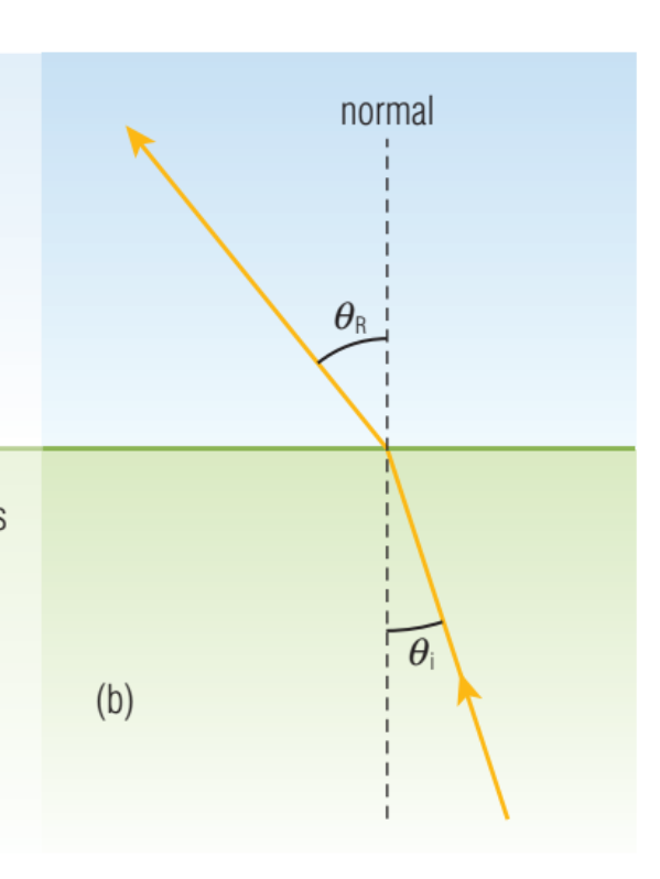
Refraction
The bending of light rays as they pass between two different media. due to changes in the speed of light.Light refracts only at the boundary when it is entering or leaving a medium.
Speed of light
3.0 × 10⁸ m/s in a vacuum. however, it is impossible for light to move at top speed when particles get in the way.
the index of refraction
also called the refractive index
the amount by which a transparent medium decreases the speed of light
the larger the refractive index, the more the medium decreases the speed of light
indicated by a number
1.00 in a vacuum - 1.003 in air technically, but we round to 1.000 since the 4th digit doesn’t matter
Caculating the index of refraction
The refractive index of a medium, n, is determined by comparing the speed of light in the medium, v, with the speed of light in a vacuum, c. n has no units, while v and c are measured in m/s

index of refraction diagram
Dispersion
the refraction of white light into separate wavelengths, or colours.
Snell’s law
a formula that uses values for the index of refraction to calculate the new angle that a ray will take as a beam of light strikes the interface between two media
the indices of refraction of the two media are n1 and n2 and the angles of incidence and the angle of refraction are θ1 and θ2

total internal reflection
light reflects completely off the inside wall of a denser medium (higher index of refraction) rather than passing through the wall into a less dense medium (lower index of refraction).
The critical angle
The angle where the refracted ray of light follows a path exactly along the surface of the medium. Where θ2 = 90 degrees.
A mirage
an image of a distant object produced as light refracts through air of different densities.
A lens
a curved transparent material that is smooth and regularly shaped so that when light strikes it, the light refracts in a predictable and useful way.
By shaping both sides of the lens, it is possible to make light rays diverge or converge as they pass through the lens.
The most important aspect of lenses is that the light rays that refract through them can be used to magnify images or to project images onto a screen. Relative to the object, the image produced by a thin lens can be real or virtual, inverted or upright, larger or smaller.
Types of lenses
converging lenses and diverging lenses
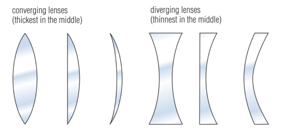
Lens Terminology
The principal axis is an imaginary line drawn through the optical centre perpendicular to both surfaces.
The axis of symmetry is an imaginary vertical line drawn through the optical centre of a lens.
Two principal focuses. The focal point where the light either comes to a
focus or appears to diverge from a focus is given the symbol F, while that on the opposite side of the lens is represented by F’
The focal length, f, is the distance from the axis of symmetry to the principal focus measured along the principal axis. Both types of thin lenses have two equal focal lengths.
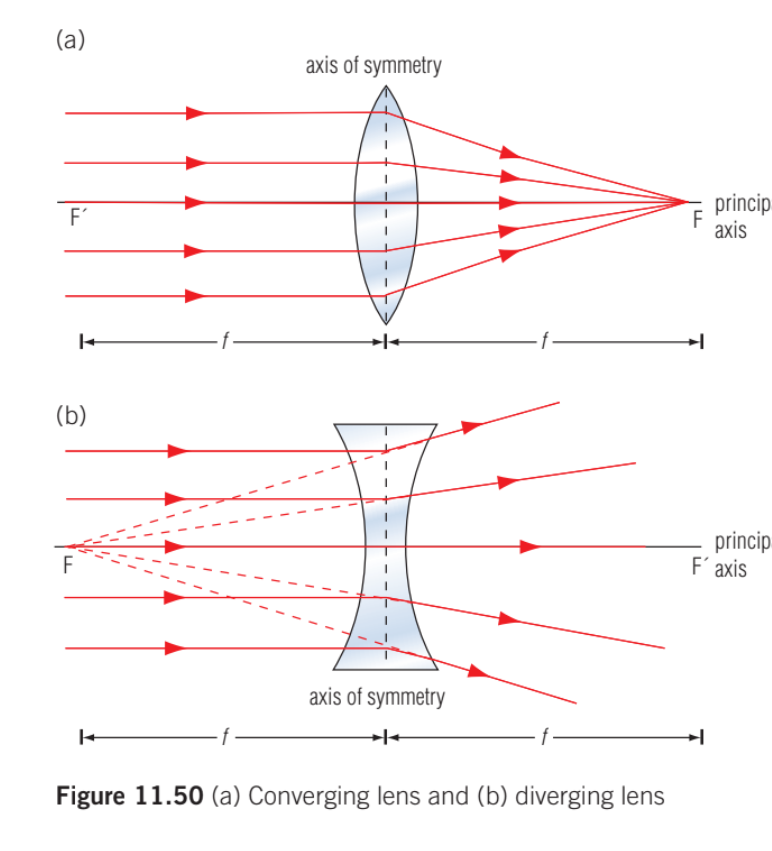
Concave lens
Otherwise known as a diverging lens. is thinner in the centre than at the edges. As parallel light rays pass through a concave lens, they are refracted away from the principal axis. This means the light rays diverge and they will never meet on the other side of the lens. The image formed is always upright and smaller than the object.
Drawing a Concave Lens Ray Diagram
1. The first ray of a concave lens ray diagram travels from the tip of the object parallel to the principal axis (ray 1). When it emerges from the lens, it appears to come from the principal focus.
2. The second ray travels from the tip of the object through the optical centre of the lens and is not refracted (ray 2).
3. Draw the virtual image where the rays appear to intersect.
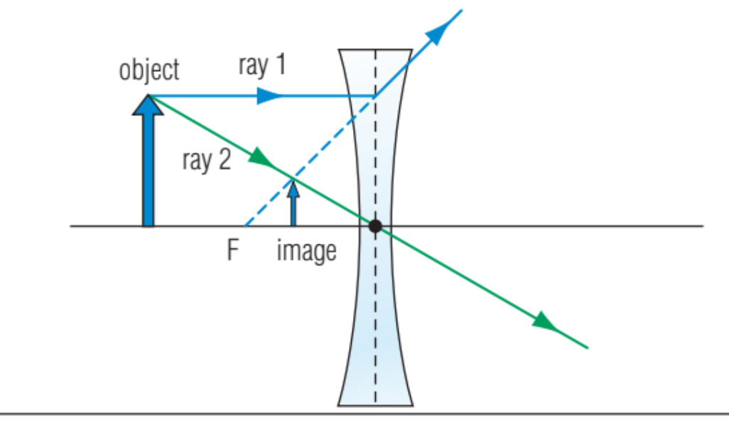
Convex lens
Also called a converging lens. thicker at the centre than at the edges. As parallel light rays travel through a convex lens, they are refracted toward the principal axis. This causes the rays to move toward each other. The light rays cross at the focal point of the lens. The image it creates is usually real and inverted unless the object is placed less than one focal length away, in which case the image is upright and virtual.
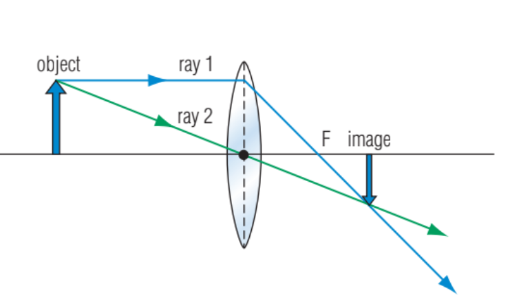
Drawing a Convex Lens Ray Diagram
1. The first ray of a convex lens ray diagram travels from the tip of the object parallel to the principal axis (ray 1). When it emerges from the lens, it passes through the principal focus.
2. The second ray travels from the tip of the object through the optical centre of the lens and is not refracted (ray 2).
3. Draw the real image where the rays appear to intersect.
