Chapter 4-Electricity and Magnetism
1/66
There's no tags or description
Looks like no tags are added yet.
Name | Mastery | Learn | Test | Matching | Spaced | Call with Kai |
|---|
No analytics yet
Send a link to your students to track their progress
67 Terms
the origin of magnetic force
any moving charged particle creates a magnetic field perpendicular to the motion of the particle
spin magnetic moment
magnetic field created from spin of electrons (or any charged particle) on their own axes
Magnetic dipoles
materials that have a spin in a dominate direction, exhibit magnetic domain. In other words, groups of atoms with their net magnetic field moving in the same direction
nonmagnetic dipoles
pairs of electrons (spin-up and spin-down) cancel each others force
flux lines
lines of force or induction, force field between N and S poles of a magnet. Stronger the magnet, more lines of flux, always flow north to south
flux density
concentration of number of lines of magnetic force (flux). Greater density, stronger magnetic field
SI unit for flux density
measured in Weber
SI unit for magnetic flux density
1 tesla = 10,000 Gauss
1 T = 1Wb/m2
Laws of magnetism
Repulsion and attraction
Inverse square law-Magnetic force is directly proportional to the product of the magnitude of the field strength, and inversely proportional to the square of the distance between them
Magnetic poles-break a bar magnet and they each still have two poles
Types of magnets
natural magnets, artificial permanent magnets, electromagnets
Natural magnets
Created when iron oxide remains in the Earth’s magnetic field for ages, slowly orienting magnetic dipoles in the same direction
Artificial permanent magnets
manufactured from steel alloy called alnico, composed of aluminum, nickel, and cobalt
Electromagnets
temporary magnet produced by moving electric current
Characteristics of magnetic materials
Permeability: ease with which a material is magnetized
Retentivity: the ability to retain magnetization
magnetic classifications of materials
ferromagnetic
Paramagnetic
Diamagnetic
Nonmagnetic
ferromagnetic
a material with high magnetic permeability
Paramagnetic
materials weakly attracted to magnetic fields
Diamagnetic
Diamagnetic materials are weakly repelled by magnetic fields and do not retain magnetism when the field is removed
Nonmagnetic
materials not affected by a magnetic field and cannot be magnetized
Solenoids
a coil consisting of a series of loops, which serve to increase flux density.
Electromagnets
solenoids with an iron core to enhance flux density (ferromagnetic core)
Requirements for generating electrical energy (3)
Conductor
Magnet field
Motion between the conductor and the magnet
electromagnetic induction
a magnetic field is induced by current flow, and likewise, current is induced when a conductor passes through a magnetic field. Presence of magnetic field isn’t enough, must have motion
Ways to create motion between lines of force
move conductor through a stationary, unchanging strength magnetic field
move magnetic lines of force through a stationary conductor with an unchanging strength magnetic field
Vary the magnetic flux strength from a stationary magnet through a stationary conductor
Mutal induction
two coils of wire placed in close proximity. AC in the primary coil “induces” a similar current flow in the secondary coil. Used in transformers
Primary coil
coil supplied with the current first
Secondary coil
the coil in which the current is induced
Self induction
Self-induction is the phenomenon where a changing current in a coil induces an electromotive force (EMF) in the same coil that opposes the change in current. Allows direct current to flow while at the same time hindering alternating current
Inductive Reactance
Opposition to the flow of alternating current produced by an inductor. measured in ohms and varies in direct proportion to frequency
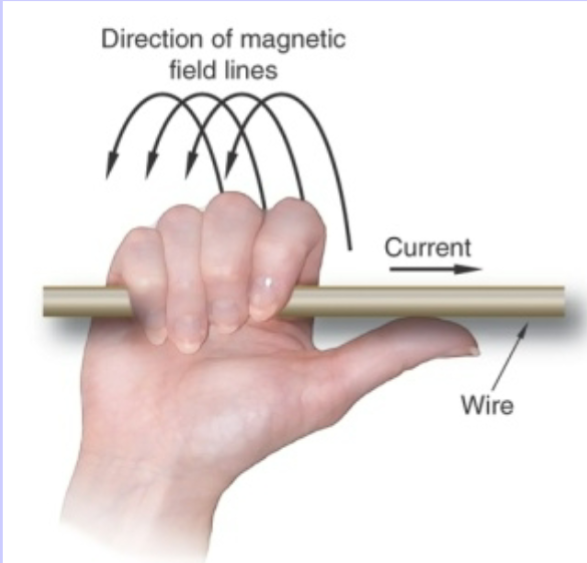
Flemmings right hand rule
The direction of the current and its associated magnetic field
Faradays law: 1st law of electromagnetics
Four factors influence induced currents:
-Strength of magnetic field
-Speed of motion
-Angle between rotating conductor and lines of force. Max at perpendicular
-Number of turns in the conductor
Generator
Converts mechanical energy (from motion) to electrical energy (current)
Armature
the rotating coil of wire at the core of an electric generator
Slip rings
To conduct electricity of an electric generator, slip rings provide contact, while turning on brushes. Whole slip rings are used for AC generators
Brushes
In contact with slip rings, current is conducted from the armature of a generator through brushes
commutator ring
a slip ring cut in half, which each half connected to one end of the armature wire. The gaps in the commutator ring create a change in the direction of current in a motor or generator. The gap eliminates reversal of polarity. used for DC generators
Motors
opposite of a generator. Same principles, simply in reverse. Motors use electrical energy to produce mechanical motion
DC motor
commutator rings provide the change in polarity for a DC power supply
AC synchronous motor
rotates at the same frequency as the AC generator
AC induction motor
an electromagnet in the stator produces the magnetic force that spins the rotor
Rotor
Spins inside the motor
Stator
The stationary part, stationary magnets around the rotor. Supplied with multiphase current, energized in sequence to turn rotor, no slip rings and brushes
Motor force principle
describes opposing magnetic fields. When a magnetic field is produced by a conductor moving in a magnetic field, the two fields will repel each other. This is what turns the rotor in an induction motor
Oscilloscope
electronic test instrument that displays voltage signals as waveforms. Root is oscillate
Ammeter
Measures current in a series circuit, in amps
volt meter
measures potential difference (voltage) across a parallel circuit
Revolutions and pulses per second
60 Hz, 120 pulses per second
Transformer
take energy and transfers energy between circuits, changing the voltage levels, either step-up or step-down.
Mutual induction
two coils of wire placed in close proximity. AC in the primary coil “induces” current flow in secondary coil. Current must be AC to induce current in secondary coil.
Primary Coil
The energized coil in an AC transformer. If number of turns in primary coil is greater than number in the secondary, it is a step-down transformer
Secondary coil
The coil in which current flow is induced in an AC transformer. If number of turns in secondary coil is greater than primary coil, it is a step-up transformer.
Transformer Law
Voltage and number of turns (N) are directly proportional, whereas volts and amps are indirectly proportional. Number of turns are inversely proportional to amps.
Vs/Vp = Ns/Np
(s = secondary, p = primary)
Autotransformer
single coil of wire with multiple taps. Controls low voltage
I2R losses (copper losses)
Impedance in a transformer due to resistance
Hysteresis losses
loss due to remagnetization of the core. Constant changing of the magnetic field causes lag in the dipoles aligning in the proper direction
Eddy Current
Impedance in a transformer due to the reversal of current. Current is working against itself as it changes direction. Eddy currents cause power loss because much of the energy is wasted as heat. Laminated cores lessen loss
Air core transformer
simple primary and secondary coil
Open core transformer
simple primary and secondary coil with iron core in coils
Closed core transformers
coil wrapped on sides of square core
Shell type transformer
primary and secondary coil share an iron core in the middle of a double square configuration. Most efficient, used in X-ray generators
Rectification
changing of AC to pulsed DC, converting alternating current into a unidirectional current, by removing or inverting that part of the wave laying on one side of the zero amplitude axis. Used in high voltage circuit to maintain current flow from the cathode to the anode
Thermionic emission
When mA heats a filament (cathode) excited electrons rise to higher orbits, forming a space charge cloud
Space Charge
a cloud of electrons surrounding the cathode, formed when mA heats a filament causing electrons to raise higher orbitals
diode
semiconducting rectifier used in the high-tension circuit of an Xray machine. Replaced vacuum (valve) tube rectifiers to produce half wave
p-n junction
p (positive) side of the diode rectifier crystal contains electron holes receptive to electron flow. n (negative) side provides electrons when half of AC cycle is in n-p direction, current flows. The other half of the cycle, in p-n direction , opposes the current flow
Thyristor (silicon controlled rectifier, SCR):
extra p-n junctions provide faster switching of current flow
Capacitors
Stores electric charges temporarily on two insulated foil strips, one strip positively charged, one negatively charged. Used in capacitor discharge portables. Unit of capacitance is the farad, which is 1 coulomb/volt