Imaging QA: Image Eval Errors
1/33
There's no tags or description
Looks like no tags are added yet.
Name | Mastery | Learn | Test | Matching | Spaced | Call with Kai |
|---|
No analytics yet
Send a link to your students to track their progress
34 Terms
Every Image MUST include (may be in DICOM header)
Required by law…
Patient Name
Patient DOB
Date of Exam
Location of Exam
Rt or Lt Markers
NOT required by law on images...
MR#
Tech’s ID (initials, etc..)
EI Number
Referring Physician
Reading Radiologist
Common Errors …
Wrong Patient - may have x-rayed correct pt, but send under wrong ID
Wrong Body Part - sent under wrong body part, wrong accession # = Hard for physician to locate
Wrong side - Wrong marker, but correct side OR wrong accession # for bilateral examinations
Wrong Annotation - Upright vs. Supine; PA vs. AP
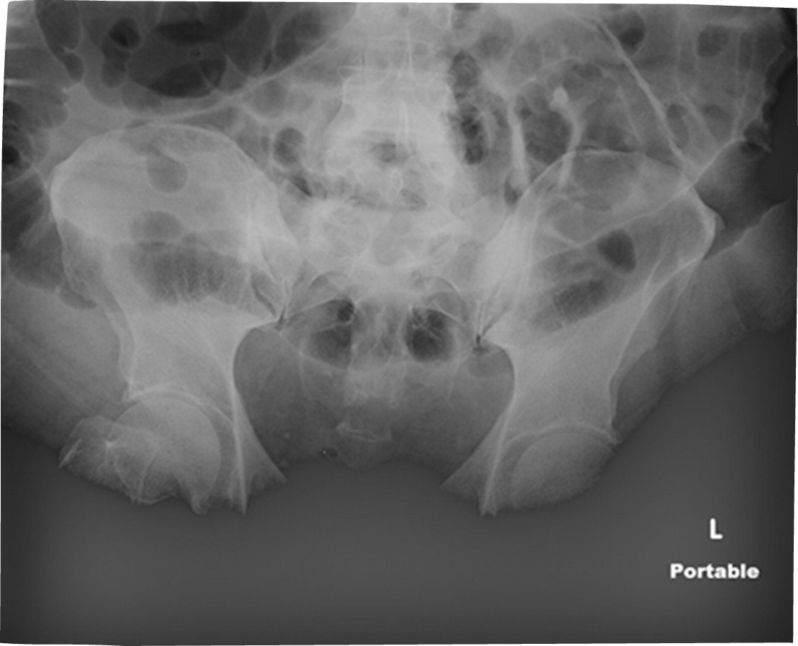
Receptor Exposure
The amount of radiation striking the receptor
Mottle
Saturation - soft tissues eliminated
patient and technical factors need consideration
S#s and EI#s are brand specific and will not be assessed on the ARRT Exam
(Image shows saturation - Maybe Big Belly? )
Processing Errors
Histogram Analysis
* Histogram analysis error- need to collimate
Values of Interest
Rescaling - Modifying image to what the computer things it should look like
LUTs - processed with the right amount of brightness and contrast
Correct Collimation is crucial - lowest exposure regions of a histogram can represent collimated borders
Asymmetrical collimation causes problems in CR b/c CR is processed looking for 2 or 4 borders
Artifacts
Any part of an image that does not accurately represent the anatomic structures present within the subject being evaluated
Damages:
Receptor physical damage to the receptor
Hyperdense artifacts
DR dexel malfunctions (Dead dels)
Damages:
Pixel Malfunctions - malfunctions with the screen
Dead or damaged pixels
Located in the exact same location every image
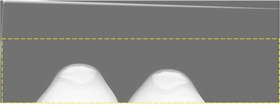
Detector Calibration Errors
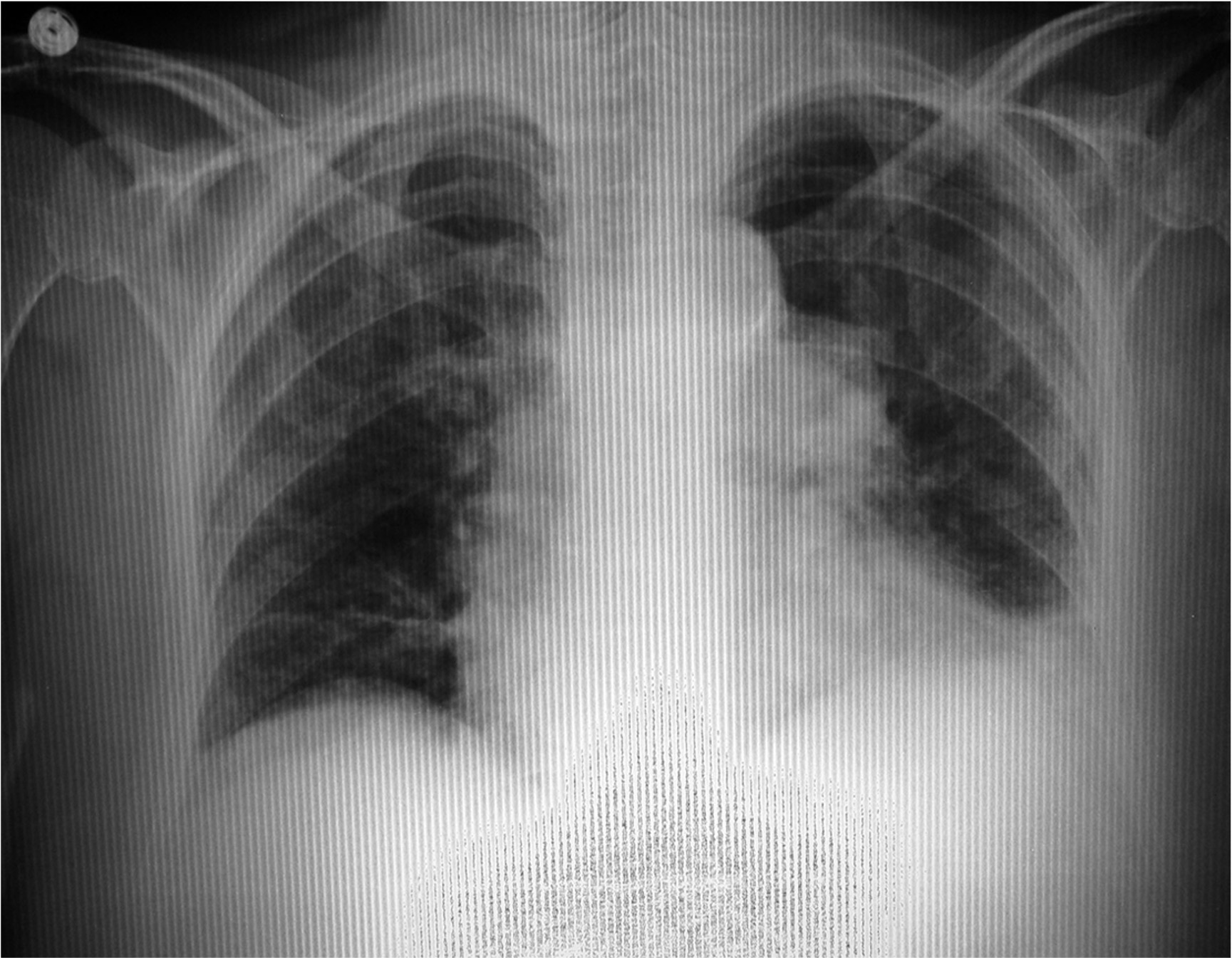
Grid Line Suppression Artifact
Dexel Drop - Out Effects
In DR systems, dead detector elements (dexels) can fail = not produce a gray square = broken
Entire rows or columns of dexels can also drop out due to electronic failure
Mild - moderate issues are compensated for
Many rows (severe), the detector plate will need to be replaced
* the most common way to correct these is using a software Kernel in which the values of the 8 pixels surrounding a dead pixel are averaged, then this value is inserted into the dead pixel
Steps
SUM eight surrounding pixels
AVERAGE these values
INSERT result into centered
Software can compensate for moderate cases of Dexel Drop-out, but not for severe cases like this (image), where whole sections of rows have dropped out
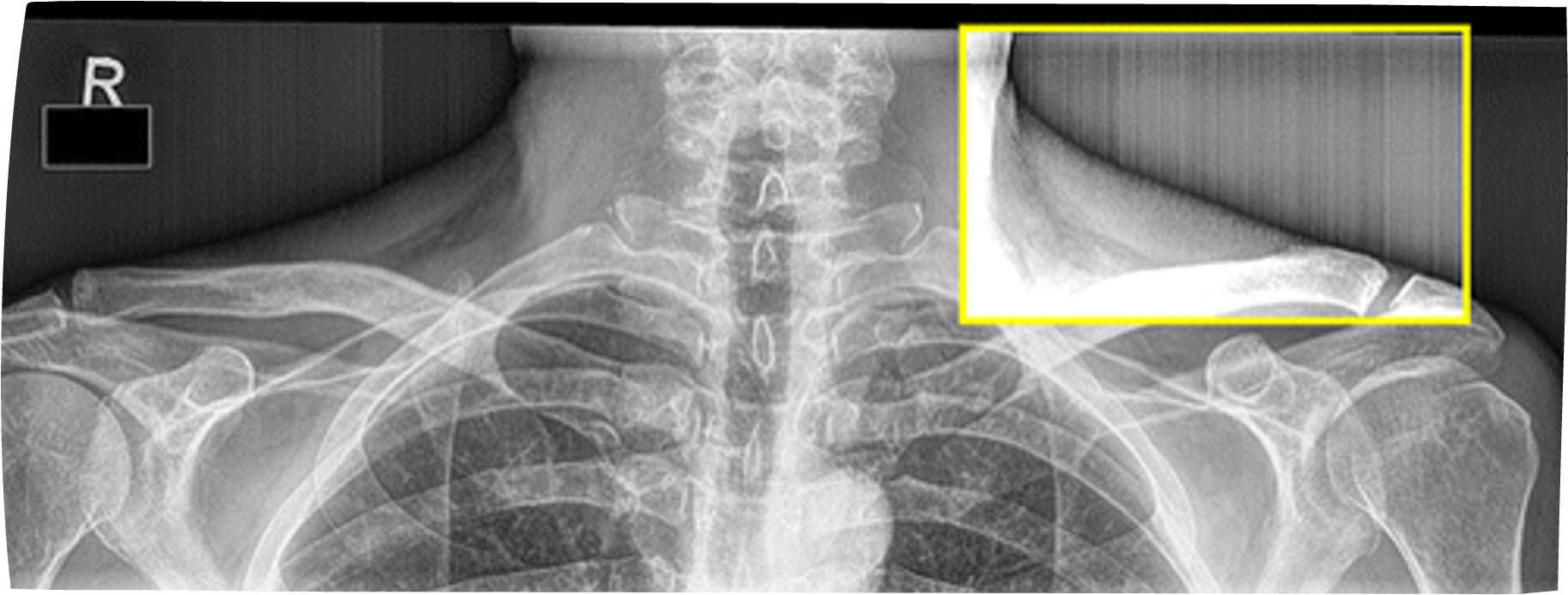
Data Clipping
If the dynamic range or bit depth of a digital processing system is too limited, it is possible for data clipping to occur when either brightness or contrast is adjusted.
The dynamic range of the software, supported by the bit depth of the computer hardware, must extend sufficiently above and below typical input values to allow for all probable adjustments to the image.
Would restrict the amount of data shared to the Radiologist and therefore limit their windowing ability.
Mid - Gray Clipping - its usually bright whites and dark blacks and that would be ok
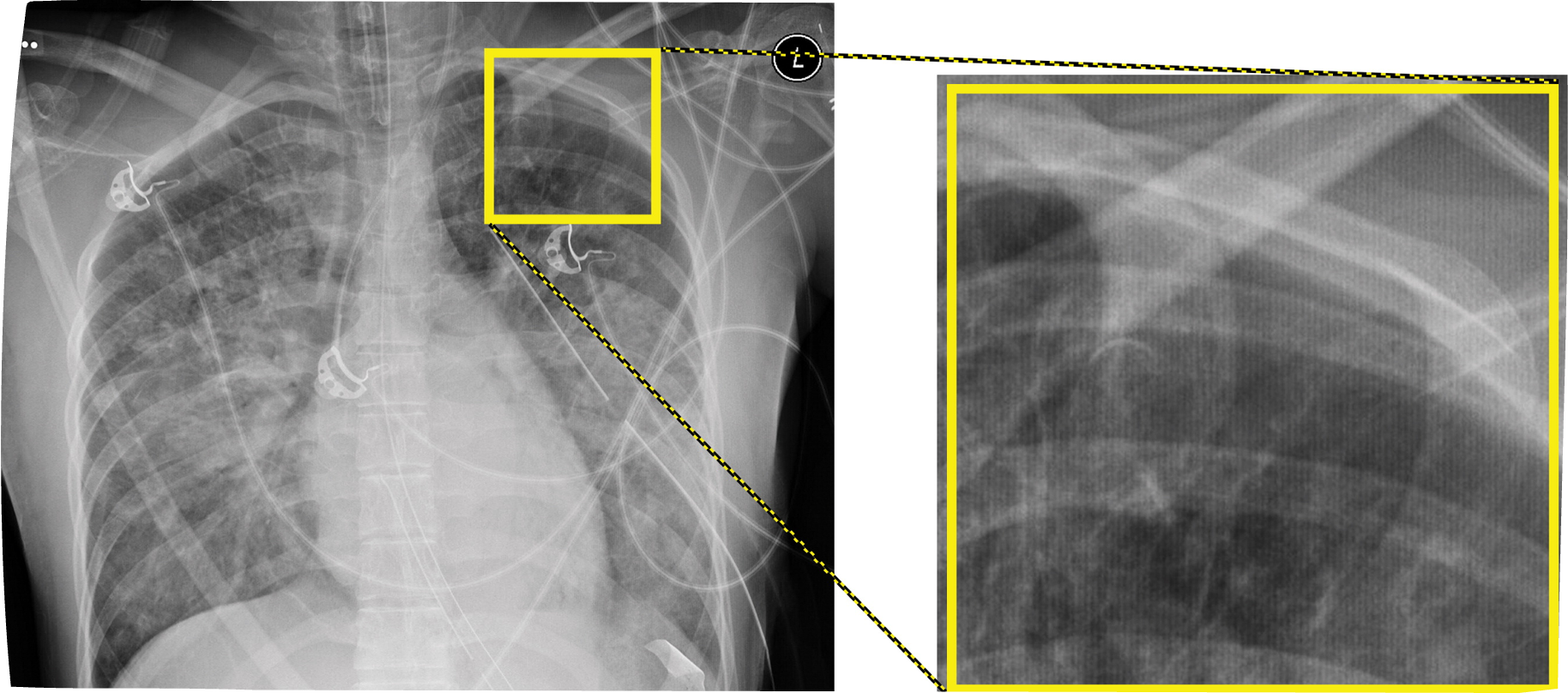
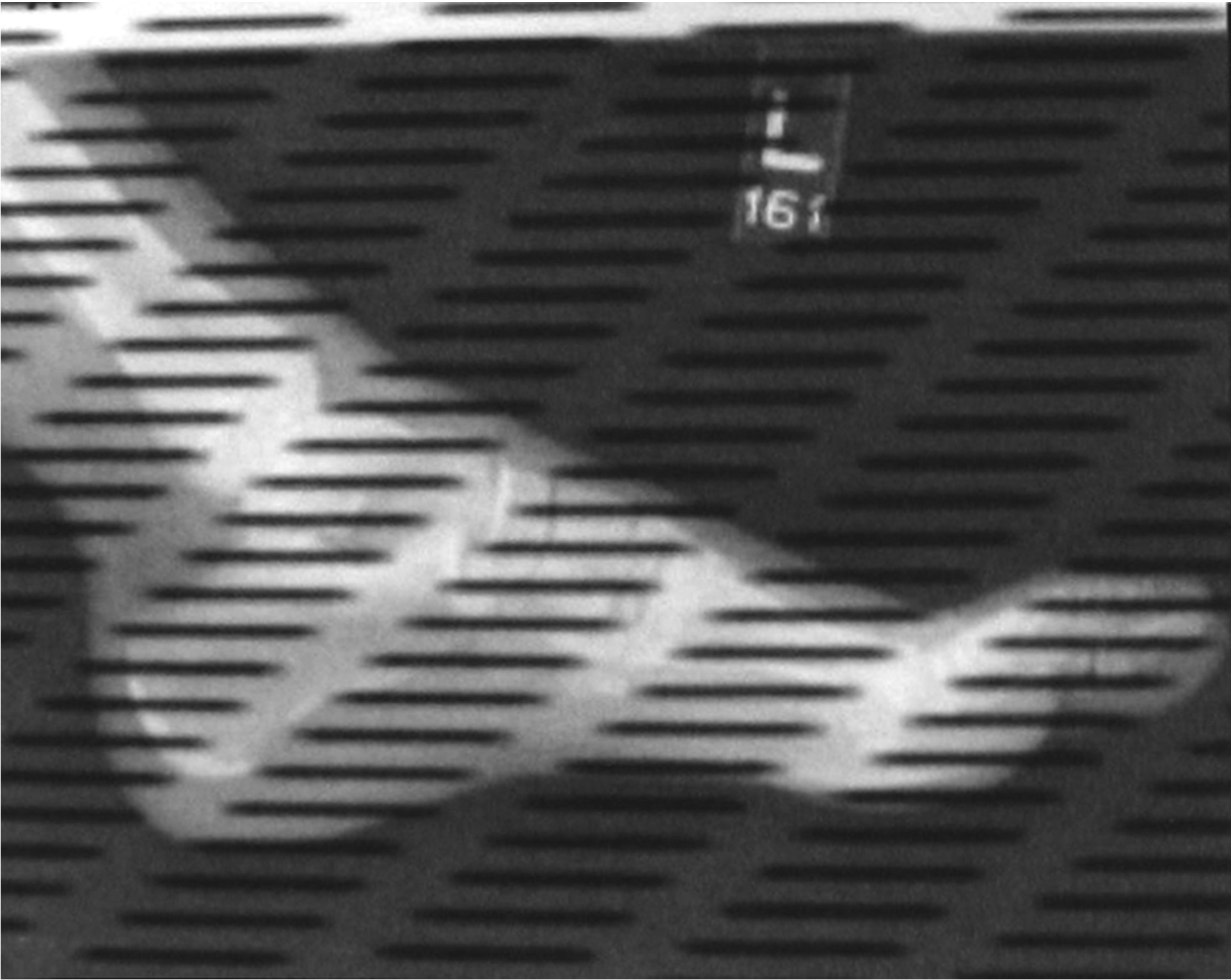
Aliasing (Moire Artifact)
An interference pattern
A false presentation of artefactual lines
One way is to overlap two similar patterns of alternating, periodic structures, especially high contrast structures, such as grid lines from two overlapping grids.
In CR Processing, an electronic version called “aliasing” is much more likely to occur if…
A stationary grid is used, and the grid lines run parallel to the scanning lines of the CR Reader
If the frequency of the grid lines is close to the scanning frequency of the CR reader and they run parallel to each other, what may occur?
Artifact
*Older grids often have a frequency of 40-50 lines/cm
TO Prevent aliasing artifacts…..
Use high - frequency grids at >50 lines per cm (expensive)
Use new multi-hole grids
Use short-dimension (SD) grids positioned such that the grid lines run perpendicular to the CR scanning lines
Long Dimension vs. Short Dimension
Lead strips run parallel vs. perpendicular
17 inch vs. 14 inches
Alignment Issues
For CR, exposure indicator errors are likely unless at least 30 percent of imaging plate is exposed
Therefore, for tightly-colllimated views of digits, it is recommended that two or three views be taken on one imaging plate.
Use at least 1/3 of the CR plate for an exposure
CR IRs come in different sizes
NOTE-
*Because they scan the receptor plate in sections, DR systems are not subject this 30% rule for plate coverage
Bilateral Projections
When “manual” technique is used, CR sytems generally have no difficulty processing bilat views without processing errors
However, when AEC is used, special care must be taken to active the two side detector cells and ensure that the anatomy is positioned directly over the energized cells, to avoid early shut-off and unacceptable mottle.
*Partition pattern recognition errors/segmentation errors
Artifacts; CR
Dust, aging phosphors, ghosting, scratches
Laser jitters = wavy appearance
Laser obstruction
Radiation Fog
Ghost Images
CR only issue
Incomplete erasure of the CR receptor
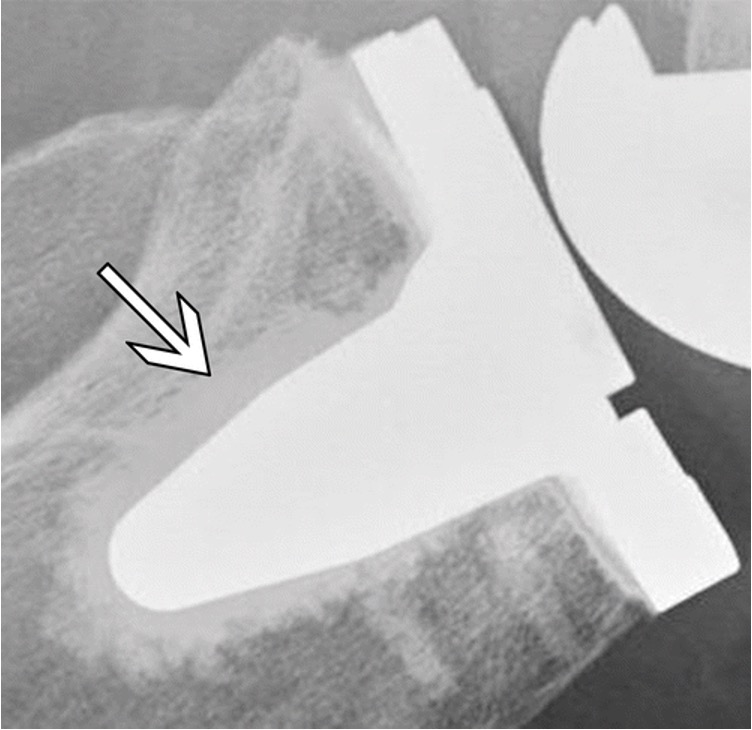
Backscatter (artifacts)
Are more likely to appear in situations with more scatter (ie, large patients or wide-open collimation) or if the x-ray beam is not fully intercepted by the detector
If projections of detector electronics are visible on a patient image, options for a repeated image include using tighter collimation (decreasing the field of view), verifying good imaging geometry, or placing additional shielding behind the detector, such as a lead apron or plate to block the backscatter from striking the detector.
Brightness
All pixel brightness levels within the anatomy of interest should be neither completely white nor pitch black, but should possess along a broad range from very light to very dark gray *see through that area
Contrast and Gray Scale
Should be such that the number of details present in the image is maximized, and there is sufficient visual differentiation between adjacent details
Signal-to-Noise Ratio
High signal, low noise = a high ratio
Must be achieved in every image by;
a. increasing the signal reaching the image receptor
b. decreasing the electronic noise, scatter radiation, and all other forms of noise (artifacts) reaching the image receptor
To ensure adequate penetration of the signal, sufficiently HIGH kVp must be used!
High SNRs are ideal for quality images
Spatial resolution (sharpness of detail)
should be apparent in electronic iamges:
at least 8 LP/mm for static images
at least 6 LP/mm for digital fluoroscopy
Depends upon:
geometrical factors in the original projection
digital processing
Vertical and horizontal resolution of the display monitor
Zoom (magnification) level
Artifacts
of all kinds must be absent
Shape Distortion
Must be minimized, such that accurate representation of the anatomy of interest is achieved
Depends entirely upon geometry of original projection
Geometric Magnification (Size Distortion)
of the original image should generally be minimized
strictly controlled by the SID/SOD ratio and related positioning
Long SID; Short OID
Measuring SID, minimizing OID
Display Magnification
of the digital image shound not be so extreme that the image becomes pixely where individual pixels become apparent and sharpness of details is lost
Controlled by display screen size, matrix size, and field of view