1750 Pelvis IA
1/41
There's no tags or description
Looks like no tags are added yet.
Name | Mastery | Learn | Test | Matching | Spaced | Call with Kai |
|---|
No analytics yet
Send a link to your students to track their progress
42 Terms
AP Projection; Pelvis and Proximal Femora (CR & SS)
Perpendicular to the midpoint of the IR
The image shows an AP projection of the pelvis and of the head, neck, trochanters, and proximal one third or one fourth of the shaft of the femora
NOTE: 1st projection that you do in a pelvis/hip series.
NOTE: You can shield for a pelvis. It is best practices that we do
AP Projection; Pelvis and Proximal Femora (Eval Criteria)
• Evidence of proper collimation
• Entire pelvis along with the proximal femora
• Both ilia and greater trochanters equidistant to the edge of the radiograph
• Lower vertebral column centered to the middle of the radiograph
• No rotation of pelvis
o Both ilia symmetric in shape
o Symmetric obturator foramina
o Ischial spines equally seen
o Sacrum and coccyx aligned with the pubic symphysis
• Proper rotation of proximal femora
o Femoral necks in their full extent without superimposition
o Greater trochanters in profile
o Lesser trochanters, if seen, visible on the medial border of the femora
• Soft tissue and bony trabecular detail
Note: Rotate lower limbs 15 to 20 degrees internally. *Must include about ¼ or 1/3 of upper femurs
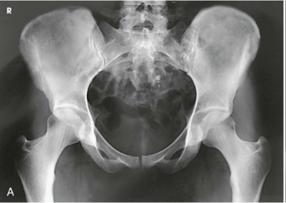
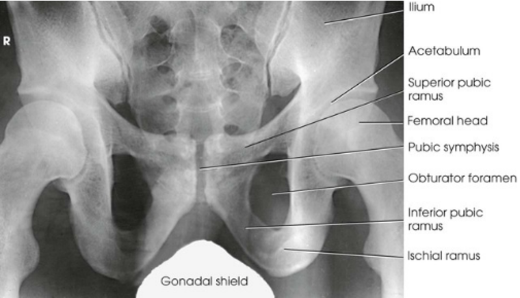
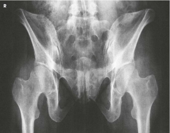
AP Projection; Pelvis and Proximal Femora
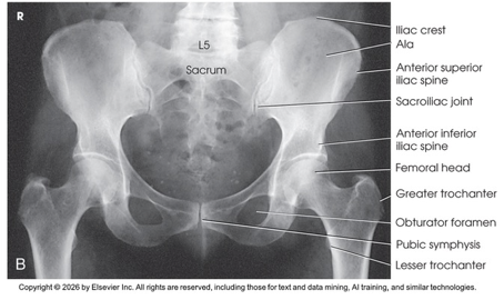
AP Projection; Pelvis and Proximal Femora (Labeled)
Why do we rotate lower limbs internally 15-20 degrees
So that lesser trochanters are not visible or in profile and femoral necks are not foreshortened (happens when limbs are externally rotated)
AP Oblique Projection; Proximal Femora and Femoral Necks; Modified Cleaves Method (CR & SS)
Perpendicular to enter the patient’s midsagittal plane at the level 1 inch (2.5 cm) superior to the pubic symphysis. For the unilateral position, direct the central ray to the femoral neck
The bilateral image shows an AP oblique projection of the femoral heads, necks, and trochanteric areas onto one radiograph for comparison
AP Oblique Projection; Proximal Femora and Femoral Necks; Modified Cleaves Method (Eval Criteria)
• Evidence of proper collimation
• No rotation of the pelvis, as demonstrated by a symmetric appearance
• Acetabulum, femoral head, and femoral neck
• Lesser trochanter on the medial side of the femur
• Femoral neck without superimposition by the greater trochanter; excess abduction causes the greater trochanter to obstruct the neck.
• Femoral axes extended from the hip bones at equal angles
• Soft tissue and bony trabecular detail
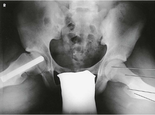
AP Oblique Projection; Proximal Femora and Femoral Necks; Modified Cleaves Method
AP Projection; Hip (CR & SS)
Perpendicular to the femoral neck; using the localizing technique place the central ray approximately 2.5 inches distal on a line drawn perpendicular to the midpoint of a line between the ASIS and the pubic symphysis
Center the IR to the central ray
Make any necessary adjustments in the IR size and central ray point when an entire orthopedic device is to be shown on one image
The resulting image shows the head, neck, trochanters, and proximal one third of the body of the femur. In the initial examination of a hip lesion, whether traumatic or pathologic in origin, the AP projection is often obtained using an IR large enough to include the entire pelvic girdle and upper femora. Progress studies may be restricted to the affected side.
(NOTE: Rotate lower limb 15-20 degrees internally)
AP Projection; Hip (Eval Criteria)
• Evidence of proper collimation
• Regions of the ilium and pubic bones adjoining the pubic symphysis
• Hip joint
• Proximal one third of the femur
• Femoral head, penetrated and seen through the acetabulum
• Entire long axis of the femoral neck not foreshortened
• Greater trochanter in profile
• Lesser trochanter usually not projected beyond the medial border of the femur, or only a very small amount of the trochanter visible
• Any orthopedic appliance in its entirety
• Soft tissue and bony trabecular detail
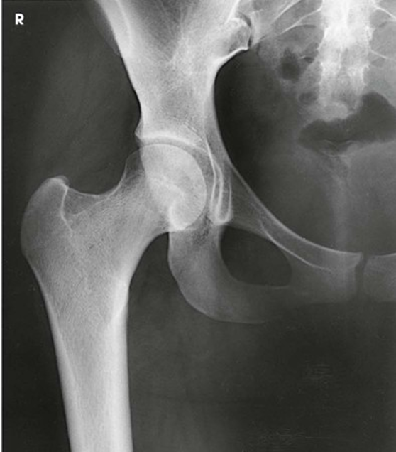
AP Projection; Hip
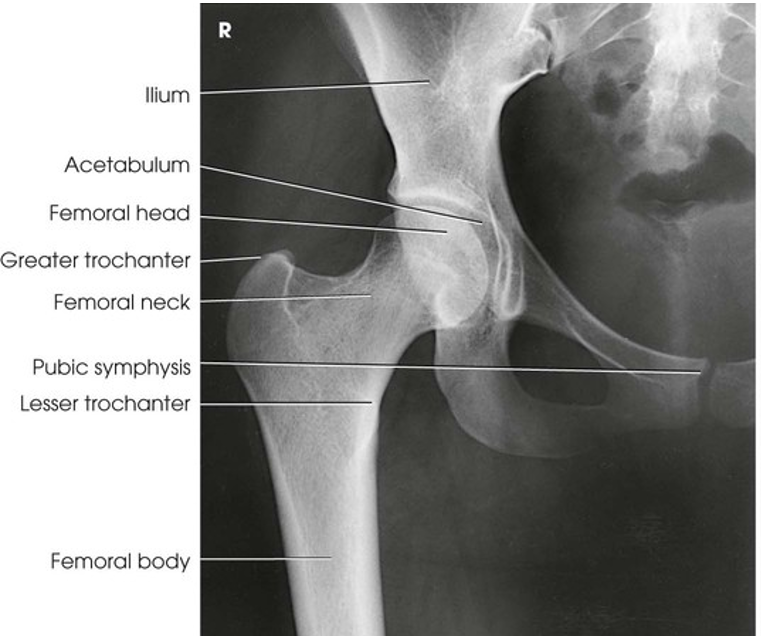
AP Projection; Hip (Labeled)
Lateral Projection; Hip; Lauenstein and Hickey Methods (CR & SS)
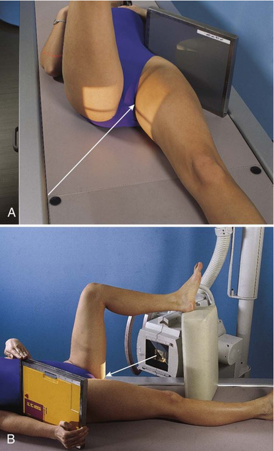
Perpendicular through the hip joint, which is located midway between the ASIS and the pubic symphysis for the Lauenstein method and at a cephalic angle of 20-25 degrees and an additional 1 inch (2.5 cm) more inferior for the Hickey method
The resulting image shows a lateral projection of the hip, including the acetabulum, the proximal end of the femur, and the relationship of the femoral head to the acetabulum
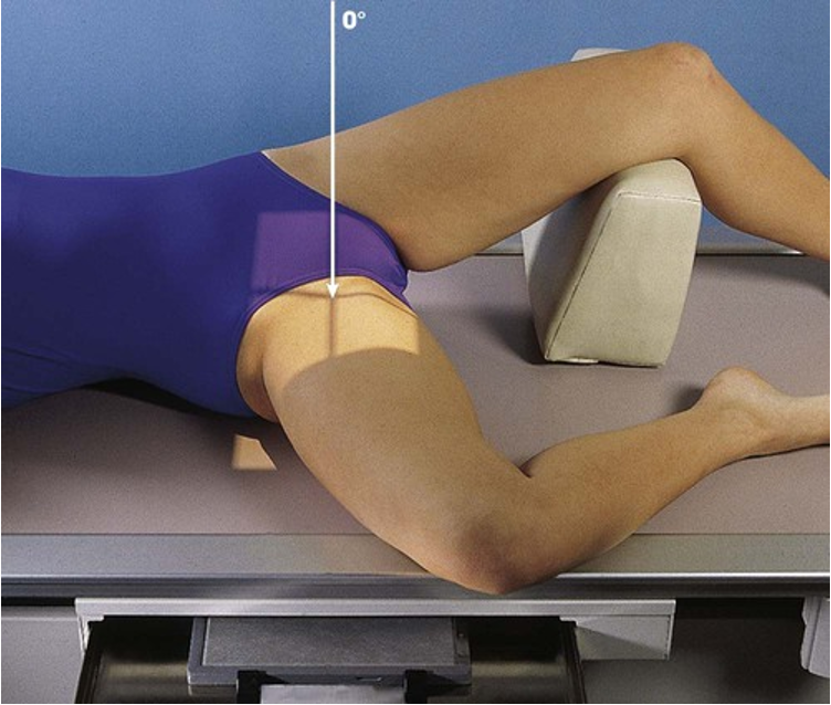
Positioning: Lateral Projection; Hip; Lauenstein and Hickey Methods (Lauenstein method)
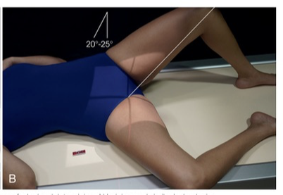
Positioning: Lateral Projection; Hip; Lauenstein and Hickey Methods (Hickey method)
Lateral Projection; Hip; Lauenstein and Hickey Methods (Eval Criteria)
• Evidence of proper collimation
• Hip joint centered to the radiograph
• Hip joint, acetabulum, and femoral head
• Femoral neck overlapped by the greater trochanter in the Lauenstein method
• With cephalic angulation in the Hickey method, the femoral neck free of superimposition
• Soft tissue and bony trabecular detail
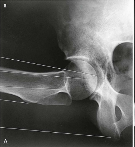
Lateral Projection; Hip; Lauenstein and Hickey Methods (Lauenstein Method)
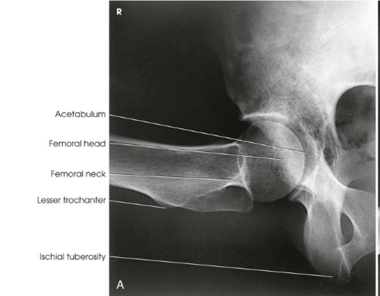
Lateral Projection; Hip; Lauenstein and Hickey Methods (Lauenstein Method) (Labeled)
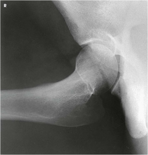
Lateral Projection; Hip; Lauenstein and Hickey Methods (Hickey Method)
Axiolateral Projection; Hip; Danelius-Miller Method (CR & SS)
Perpendicular to the long axis of the femoral neck. The central ray enters the groin area at a point midway between the anterior and posterior surfaces of the upper thigh and passes through the femoral neck, which is about 2.5 inches (6.4 cm) below the point of intersection of the localization lines
The resulting image shows the acetabulum, head, neck, and trochanters of the femur
POSITIONING: Axiolateral Projection; Hip; Danelius-Miller Method
Axiolateral Projection; Hip; Danelius-Miller Method (Eval Criteria)
• Evidence of proper collimation
• Hip joint with the acetabulum
• Femoral neck without overlap from the greater trochanter
• Small amount of the lesser trochanter on the posterior surface of the femur
• Small amount of the greater trochanter on the anterior and posterior surfaces of the proximal femur when the femur is properly inverted
• Ischial tuberosity below the femoral head and neck
• Soft tissue shadow of the unaffected thigh not overlapping the hip joint or proximal femur
• Any orthopedic appliance in its entirety
• Soft tissue and bony trabecular detail
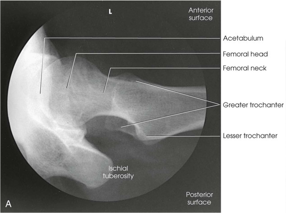
Axiolateral Projection; Hip; Danelius-Miller Method
Modified Axiolateral Projection; Hip; Clements-Nakayama Modification (CR & SS)
Directed 15 degrees posteriorly and aligned perpendicular to the femoral neck and the grid IR
This leg position shows a lateral hip image because the central ray is angled 15 degrees posterior instead of the toes being medially rotated. The resulting image shows the acetabulum and the proximal femur, including the head, neck, and trochanters, in lateral profile. The Clements-Nakayama modification can be compared with the Danelius-Miller approach described previously
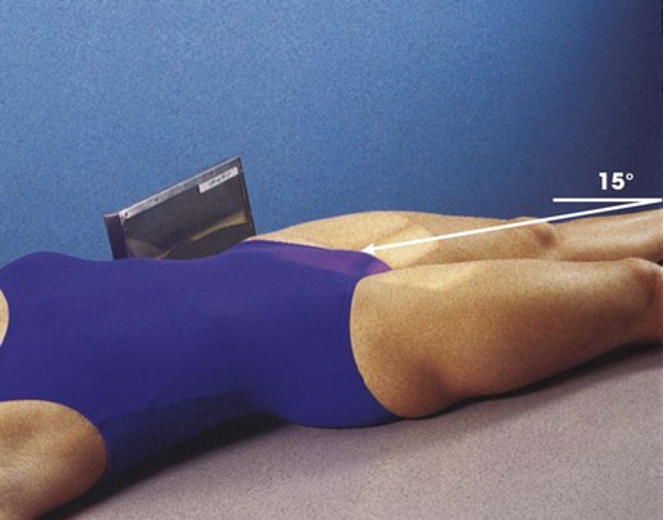
POSITIONING: Modified Axiolateral Projection; Hip; Clements-Nakayama Modification
Modified Axiolateral Projection; Hip; Clements-Nakayama Modification (Eval Criteria)
• Evidence of proper collimation
• Hip joint with the acetabulum
• Femoral head, neck, and trochanters
• Any orthopedic appliance in its entirety
• Soft tissue and bony trabecular detail
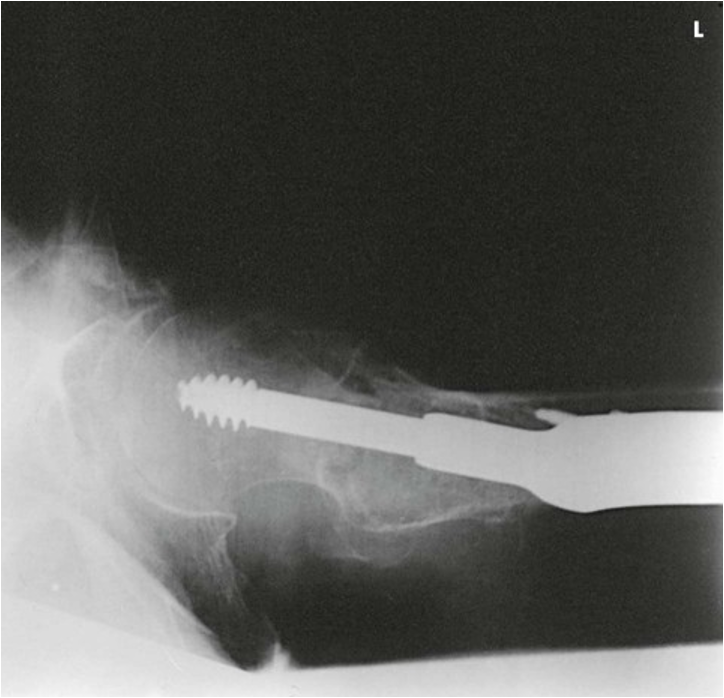
Modified Axiolateral Projection; Hip; Clements-Nakayama Modification
AP Oblique Projection; Acetabulum; Judet Method; RPO and LPO Positions (CR & SS)
Central Ray
Internal oblique - Perpendicular to the IR and entering 2 inches (5 cm) inferior to the ASIS of the affected side
The internal oblique position is used for a patient with a suspected fracture of the iliopubic column (anterior) and the posterior rim of the acetabulum
External oblique - Perpendicular to the IR and entering at the pubic symphysis
The external oblique is used for a patient with a suspected fracture of the ilioischial column (posterior) and the anterior rim of the acetabulum
The resulting image shows the acetabular rim
(Note: Both images are performed to demonstrate the entire acetabulum as well as the iliopubic and ilioischial columns of the affected side)
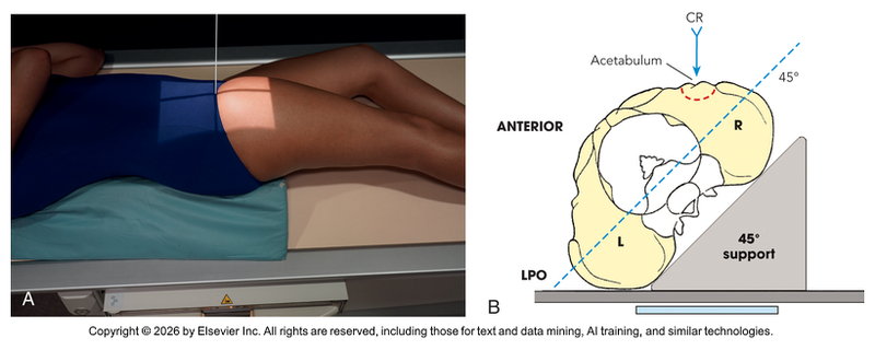
POSITIONING: AP Oblique Projection; Acetabulum; Judet Method; RPO and LPO Positions (Internal Oblique for Right Hip)
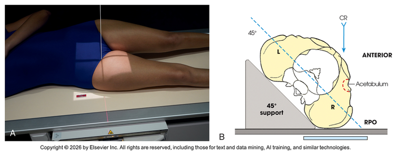
POSITIONING: AP Oblique Projection; Acetabulum; Judet Method; RPO and LPO Positions (External Oblique for Right Hip)
AP Oblique Projection; Acetabulum; Judet Method; RPO and LPO Positions (Eval Criteria)
• Evidence of proper collimation
• Acetabulum centered to the IR
• The iliopubic column and the posterior rim of the affected acetabulum on the internal oblique
• The ilioischial column and the anterior rim of the acetabulum on the external oblique
• Soft tissue and bony trabecular detail
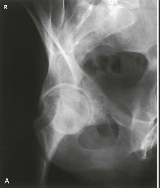
AP Oblique Projection; Acetabulum; Judet Method; RPO and LPO Positions (Internal)
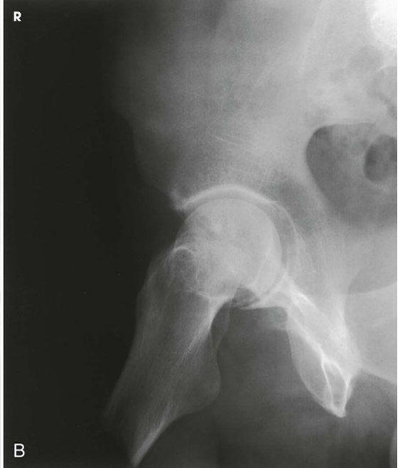
AP Oblique Projection; Acetabulum; Judet Method; RPO and LPO Positions (External)
Superoinferior Axial Inlet Projection; Anterior Pelvic Bones; Bridgman Method (CR & SS)
Directed 40 degrees caudad, entering the midline at the level of the ASIS
The resulting image shows an axial projection of the pelvic ring, or inlet, in its entirety
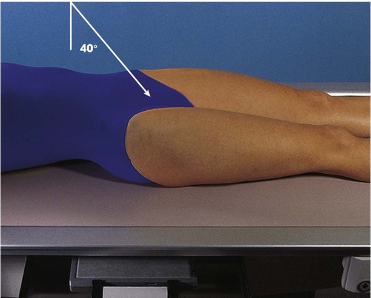
POSITIONING: Superoinferior Axial Inlet Projection; Anterior Pelvic Bones; Bridgman Method
Superoinferior Axial Inlet Projection; Anterior Pelvic Bones; Bridgman Method (Eval Criteria)
• Evidence of proper collimation
• Medially superimposed superior and inferior rami of the pubic bones
• Nearly superimposed lateral two thirds of the pubic and ischial bones
• Symmetric pubes and ischial spines
• Hip joints
• Anterior pelvic bones
• Soft tissue and bony trabecular detail
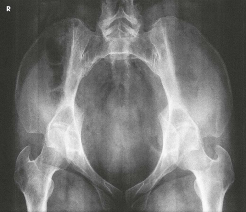
Superoinferior Axial Inlet Projection; Anterior Pelvic Bones; Bridgman Method
AP Axial Outlet Projection; Anterior Pelvic Bones; Taylor Method (CR & SS)
Central Ray
MEN: Directed 20-35 degrees cephalad and entering the midline at a point 2 inches (5 cm) inferior to the superior border of the pubic symphysis
WOMEN: Directed 30-45 degrees cephalad and entering the midline at a point 2 inches (5 cm) inferior to the superior border of the pubic symphysis
The resulting image shows the superior and inferior rami without the foreshortening seen in a PA or AP projection because the central ray is more perpendicular to the rami
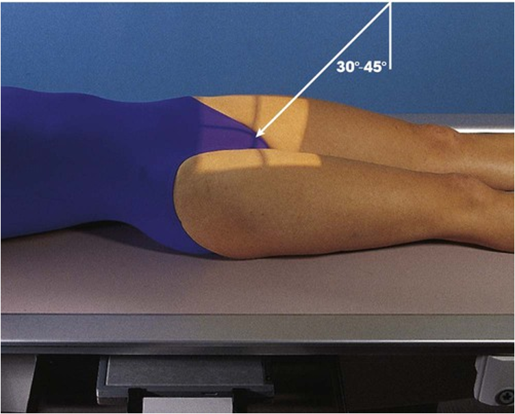
POSITIONING: AP Axial Outlet Projection; Anterior Pelvic Bones; Taylor Method
AP Axial Outlet Projection; Anterior Pelvic Bones; Taylor Method (Eval Criteria)
• Evidence of proper collimation
• Pubic and ischial bones magnified with pubic bones superimposed over the sacrum and coccyx
• Symmetric obturator foramina
• Pubic and ischial rami near the center of the radiograph
• Hip joints
• Soft tissue and bony trabecular detail
AP Axial Outlet Projection; Anterior Pelvic Bones; Taylor Method (Male)
AP Axial Outlet Projection; Anterior Pelvic Bones; Taylor Method (Female)