4TH Edition Jet charactaristics
1/84
There's no tags or description
Looks like no tags are added yet.
Name | Mastery | Learn | Test | Matching | Spaced | Call with Kai |
|---|
No analytics yet
Send a link to your students to track their progress
85 Terms
Lift vs. Propulsion
Early "tower jumpers" mistakenly believed Flapping was only source of Power
their failures helped pioneers distinguish between:
Lift→generated by Wing
Propulsion→generated by Engine
Sir George Cayley
Father of Aerodynamics
the First to Identify & Name (4 forces of flight) Lift, Weight, Thrust, and Drag.
The Wright "Flyer" Specifications
A biplane with a 40-foot wingspan, weighing 605 pounds, powered by a 12-horsepower engine.
1903
The date of the first sustained, controlled, powered flight at Kill Devil Hills; Orville flew 120 feet in 12 seconds, while Wilbur flew 852 feet in 59 seconds.
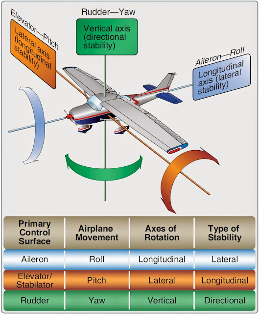
Three-Axis Control
System developed by Wright brothers to
control an A/C in Roll, Pitch, Yaw.
De Havilland Comet
World's 1st Commercial Jet Airliner (1952),
a low-wing monoplane powered by four jet engines embedded in the wing roots;
it required a crew of four (two pilots, flight engineer, navigator).
Modern Jet Cruise Performance
Aircraft routinely cruise at speeds over 500 mph (Mach 0.85)
at altitudes above 40,000 feet.
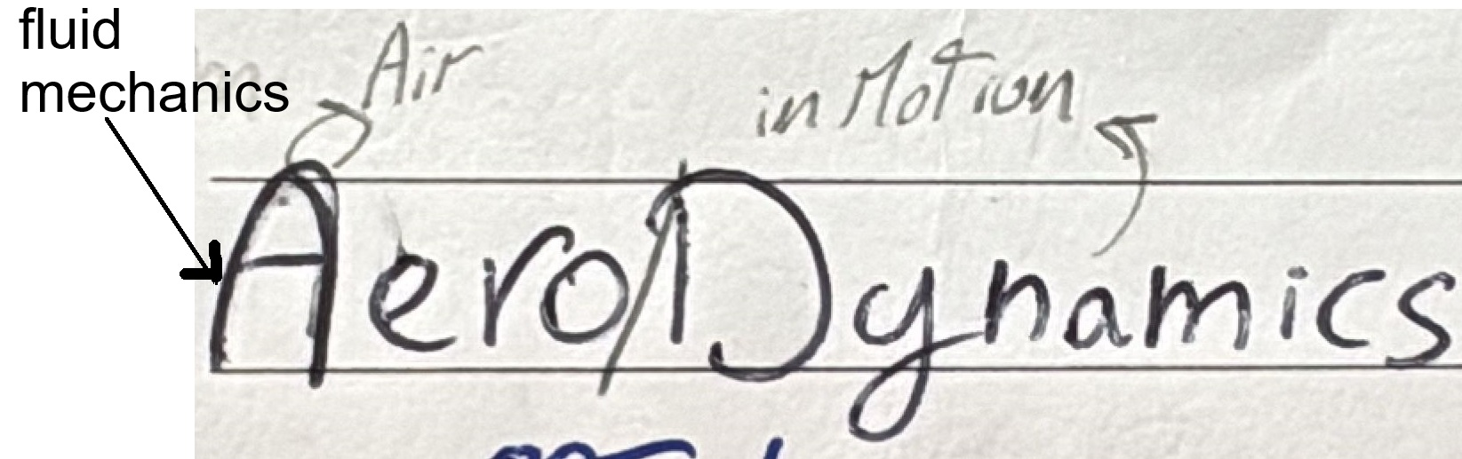
Aerodynamics
Branch of Fluid Mechanics studing Air in Motion and
Forces Acting on Bodies moving Through it
(Main science that Aviation is Based on)
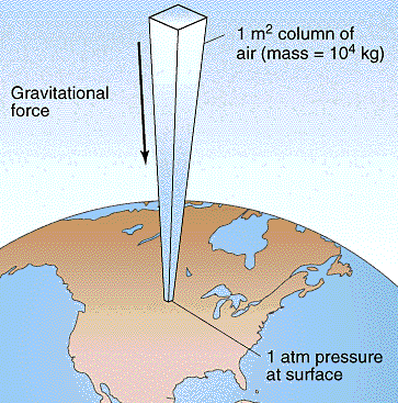
Pressure (Atmospheric or Barometric)
Force per Unit Area Exerted on a body, Above Atmospheric Column
Decreases as Altitude Increases
Standard Lapse Rate
In ISA, temperature decreases at a rate of 1.98°C (approximately 2°C) per 1,000 feet of altitude gain up to the tropopause (36,089 feet).
ISA Sea Level Conditions
Standard baseline conditions defined as 1013.25 hPa (29.92 inHg) and +15°C.
Law of Conservation of Mass
States that matter cannot be created or destroyed; in subsonic steady flow, the mass of air entering a streamtube must equal the mass exiting it.
Continuity Equation
A x V = Constant; for incompressible subsonic flow, if the cross-sectional area (A) of a streamtube decreases, the velocity (V) must increase to maintain constant mass flow.
Newton’s First Law (Inertia)
A body at rest remains at rest, and a body in motion remains in motion at a constant velocity unless acted upon by an external unbalanced force.
Newton’s Second Law (Acceleration)
F = m x a; the acceleration of an object is directly proportional to the net force acting on it and inversely proportional to its mass.
Newton’s Third Law (Action-Reaction)
For every action, there is an equal and opposite reaction; a wing generates lift by deflecting air downward (action), and the reaction force pushes the wing upward.
Bernoulli’s Principle
As the velocity of a fluid increases, its pressure decreases; this pressure differential between the upper and lower surfaces of an airfoil creates Lift.
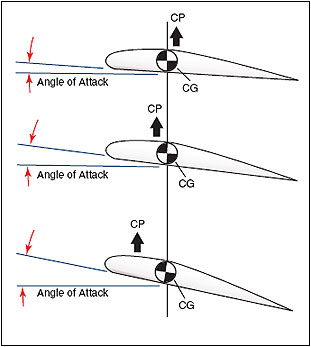
Center of Pressure (CP)
Point on Chord line where the Aerodynamic Force Acts.
The single point through which the net aerodynamic force resulting from pressure distribution around the airfoil acts.
The Lift Equation
L = ½ x ρ x V² x S x CL; lift is directly proportional to air density (ρ), the square of the velocity (V²), wing surface area (S), and the coefficient of lift (CL).
Coefficient of Lift (CL)
A dimensionless number representing lift generation efficiency; it increases linearly with the angle of attack until the critical angle is reached.
Critical Angle of Attack
The specific angle where smooth airflow over the upper surface begins to separate; the highest value of CL achieved here is CLmax.
Stall
A condition beyond the critical angle of attack where airflow separation becomes severe, leading to a rapid decrease in CL.
Relative Wind
The direction of airflow encountered by the airfoil, always parallel to and opposite the flight path of the aircraft.
Angle of Attack (AOA or α)
The angle between the Chord Line of the wing and the direction of the Relative Wind.
Indicated Airspeed (IAS)
The speed read directly from the indicator, uncorrected for errors; the primary reference for dynamic pressure and aerodynamic forces.
Calibrated Airspeed (CAS)
IAS corrected for position and instrument error; used for performance calculations and regulatory V-speeds.
Equivalent Airspeed (EAS)
CAS corrected for compressibility error at high speeds; represents actual dynamic pressure for structural analysis.
True Airspeed (TAS)
EAS corrected for non-standard air density; the actual speed relative to undisturbed air; it increases relative to IAS as altitude increases.
Ground Speed (GS)
TAS corrected for wind; the actual speed of the aircraft over the ground.
Total Drag
The sum of Parasite Drag and Induced Drag.
Induced Drag
A direct by-product of lift caused by wingtip vortices; it is inversely proportional to airspeed and dominant at low speeds/high AOA.
Parasite Drag
Drag not associated with lift, consisting of Form Drag, Skin Friction Drag, and Interference Drag; it is proportional to the square of the airspeed.
L/D MAX
The speed at which minimum total drag occurs; provides the best glide range and most efficient cruise performance.
Chord Line
An imaginary straight line connecting the leading and trailing edges of an airfoil.
Mean Camber Line
A line drawn halfway between the upper and lower surfaces of an airfoil; the distance between this and the chord line is the Camber.
Four Forces of Flight
Lift (opposes weight), Weight (acts through CG), Thrust (opposes drag), and Drag (opposes thrust); they are in equilibrium during steady, unaccelerated flight.
Wing Planforms
Rectangular (simple, good stall), Elliptical (ideal minimum induced drag), Tapered (practical compromise for jets), Delta (excellent high-speed, poor low-speed).
Wingspan (b)
The tip-to-tip length of the wing; a longer span reduces induced drag by making wingtip vortices weaker and further apart.
Wing Sweep (Λ)
The angle used to delay compressibility effects; it allows a higher TAS before local airflow reaches sonic speeds by reducing the chordwise velocity component.
Mean Aerodynamic Chord (MAC)
The chord of an imaginary rectangular wing with the same aerodynamic characteristics as the actual wing; CG is typically referenced as a percentage of MAC.
Aspect Ratio (AR)
AR = b² / S; high AR (long/narrow) is efficient for endurance; low AR (short/stubby) is better for high speeds and structural strength.
Dihedral (Γ)
The upward angle of wings from horizontal; contributes to lateral stability by increasing the effective AOA on the lower wing during a bank.
Angle of Incidence
The fixed angle between the wing's chord line and the aircraft's longitudinal axis.
Compressibility
Describes the change in volume of a medium when force is applied; air is highly compressible due to spread-out particles, which affects aerodynamics at high speeds.
Speed of Sound Formula (kts)
a = 39 x √ (273 + SAT °C); it depends solely on the temperature of the medium.
Shock Wave
A boundary line between undisturbed and compressed air where there is a sudden change in temperature, velocity, pressure, and density; causes wave drag.
Mach Number (M)
The ratio of True Airspeed (TAS) to the actual speed of sound (a); M = TAS / a.
Speed Regimes
Subsonic (below 0.75 M), Transonic (0.75 - 1.20 M), Supersonic (1.20 - 5.00 M), Hypersonic (above 5.00 M).
Critical Mach Number (Mcrit)
The speed at which local airflow over the wing first reaches sonic velocity; defined as the speed where the Coefficient of Drag rises by 0.002%.
VMO / MMO
Maximum operating speeds where normal handling qualities and structural strength are guaranteed; MMO is always below the critical Mach number.
VDF / MDF
Maximum demonstrated flight diving speeds used during certification; handling qualities are reduced at these speeds.
Vortex Generators
Small airfoils that energize the boundary layer by mixing high-energy air from outside, delaying airflow separation and increasing the critical Mach number.
Mach Tuck (Tuck Under)
A nose-down pitching moment caused by the center of pressure moving aft due to shock wave formation at high Mach numbers.
Dutch Roll
A coupled yaw-rolling oscillation common in swept-wing aircraft due to reduced inherent damping and strong roll-yaw coupling.
Four-Stage Engine Cycle
Intake, Compression, Combustion, and Exhaust; shared by both reciprocating and jet engines.
Propeller vs. Jet Thrust
A propeller moves a large mass of air with small acceleration; a jet moves a smaller mass of air with extremely large acceleration.
Compression Ratio
The ratio of the compressor's output pressure to its input pressure; higher ratios (e.g., 30:1) indicate superior efficiency.
Centrifugal Flow Compressor
Consists of an impeller, diffuser, and manifold; limited by a 90-degree airflow turn and lower compression ratios (approx 4:1 per stage).
Axial Flow Compressor
Consists of multiple stages of rotating rotor blades and stationary stator vanes; air flows axially, allowing for high compression ratios and streamlined design.
Multi-Spool Engine
Features independent compressors (N1, N2) on separate shafts rotating at optimal speeds; allows ratios up to 30:1 and reduces stall risk.
Combustion Chamber Air Split
Approximately 25% of compressed air is used for combustion; 75% bypasses for cooling the liner and diluting exhaust to protect turbine materials.
Nozzle Guide Vanes (NGVs)
Stationary vanes in the turbine section located before rotating blades; they accelerate and direct gas flow at the optimal angle.
Engine Surge
A reverse flow caused by shock waves in the exhaust nozzle if gas velocity exceeds the speed of sound; can lead to engine failure.
Turbofan Engine
The standard for modern jets; divides air into core flow and bypass flow, yielding high propulsive efficiency and lower noise.
Bypass Ratio
The ratio of bypass (cold) air to core (hot) air; in high-bypass engines (e.g., 5:1), the fan provides up to 80% of total thrust.
Thrust Reverser Types
Bucket (hot stream), Clamshell (hot stream), and Cold-Stream (standard for high-bypass, redirects only bypass air).
Fuel Control Unit (FCU)
The "brain" of the engine system; meters precise fuel based on altitude, temperature, and throttle setting.
Station Pt2
The designation for Total Pressure at the engine inlet (station 2).
N1 and N2 Indicators
N1 shows the rotational speed of the low-pressure compressor/fan; N2 shows the rotational speed of the high-pressure compressor.
Sound Damage Threshold
Sound intensities above 120 dB can cause permanent hearing damage; a jet at takeoff can produce 155 dB near the inlet.
Noise Types
Jet Exhaust Noise (Broadband, from turbulence) and Compressor/Fan Noise (Tonal, "whining" from blades).
Primary Flight Controls
Ailerons (Roll/Longitudinal Axis), Elevator (Pitch/Lateral Axis), and Rudder (Yaw/Vertical Axis).
Artificial Feel System
Replicates natural resistance in hydraulic systems by using airspeed inputs to make controls heavier at high speeds.
Fly-By-Wire (FBW)
A system where pilot commands are sent as electrical signals to computers, which then move hydraulic actuators; Airbus A320 was the first full digital FBW airliner.
Trimmable Horizontal Stabilizer (THS)
Pivots the entire stabilizer to provide trim across a wide CG range, allowing elevators to remain streamlined and reducing trim drag.
Low-Speed Ailerons
Outboard ailerons active only at low speeds (flaps extended) to prevent wing twist, control reversal, or shock-induced "aileron snatch" at high speeds.
Rudder Limiter
Automatically restricts maximum rudder travel as airspeed increases to protect the vertical stabilizer from structural overstress.
Slotted Flaps
Increase camber and area while allowing high-energy air to flow through a slot to re-energize the boundary layer and delay separation.
Slats
Leading-edge devices that create a slot to accelerate air over the top surface, increasing CLmax and allowing a higher critical angle of attack.
Speed Brakes
Spoiler panels raised symmetrically to increase drag and descent rate; they increase stall speed slightly and are most effective at high speeds.
Ground Spoilers
Deploy automatically upon touchdown to "dump" lift and transfer aircraft weight to the wheels for maximum braking effectiveness.
Alpha Floor
An automatic protection that advances thrust to TOGA if the angle of attack reaches a predetermined value near the stall.
Stick Shaker
An artificial tactile warning system that vibrates the control column to simulate aerodynamic buffet as the aircraft approaches a stall.
Yaw Damper
An automatic system that commands rudder movements to dampen Dutch roll oscillations and improve directional stability.
Mach Trim
Provides automatic nose-up elevator input as the aircraft approaches Mcrit to counteract Mach tuck.