Fracture Mechanics
1/13
Earn XP
Description and Tags
1. Assess the question, 2. Attempt question on Paper/ Chalkboard, 3. Look at answers & assess level of knowledge
Name | Mastery | Learn | Test | Matching | Spaced |
|---|
No study sessions yet.
14 Terms
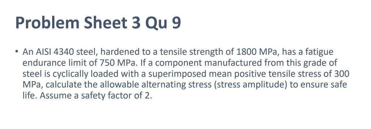
Find Stress Amplitude ?
Endurance limit given
Tensile Strength = UTS, needed for Calculation
Determine which model to use to evaluate fatigue life based on material properties and loading conditions: Soderberg (based on Yield Stress) , Goodman (based on UTS) & Gerber (non-linear & UTS squared)
Using Goodman model as Yield Stress isn’t given & linear.
Rearrange equations for Stress Amplitude
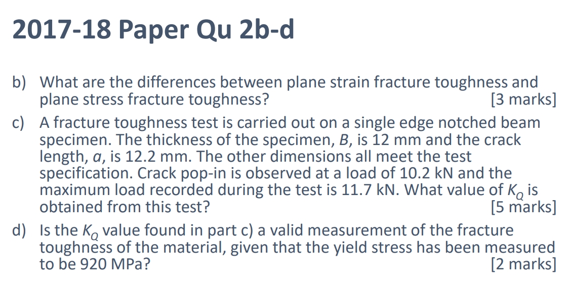
🧠 What are the differences between plane strain fracture toughness and plane stress fracture toughness?
Hint: Think about thickness, crack-tip constraints, and toughness values.
Plane Strain Fracture Toughness (KIcK_{Ic}KIc):
Occurs in thick specimens.
Out-of-plane deformation is restrained.
Offers smaller plastic zone
Used for conservative (safe) design.
Plane Stress Fracture Toughness:
Occurs in thin specimens.
Material can deform in all directions.
Less constraint → higher apparent toughness.
Comparison:
K IC, plane strain < K plane stress
Plane strain gives a worst-case estimate of material fracture resistance.

🔧 A SENB specimen with B=12 mm,a=12.2 mmB = 12 \text{ mm}, a = 12.2 \text{ mm}B=12 mm,a=12.2 mm, pop-in at 10.2 kN, max load 11.7 kN. What is KQ?
Force at Crack Pop (not Max Load !!!)
Find f(a/w)
Input into KQ equation
VALIDITY CHECKS: (gives most of marks)
Pmax / PQ < 1.1
Check smallest parameter & complete validity check
🔬 What is the purpose of plane strain fracture toughness testing (e.g. SENB and CT specimens)?
Measure the material’s resistance to crack growth in the most conservative (least tough) condition: plane strain. Due to smallest plastic zone .
🔍 How is crack initiation (PQ) identified in SENB/CT tests?
Hint: 3 types of failure, Pmax rules.
To find PQ:
Type I: PQ = PS (load where deviation starts)
Type II: PQ = Highest load before PS (pop-in)
Type III: PQ = Pmax (brittle fracture)
Check validity:
Pmax / PQ < 1.10
If not, PQ invalid → test fails

📉 A steel plate with a 20 cm crack is subjected to 65 MPa stress. How do you calculate the safety factor using the R6 diagram?
Draw a diagram of the component, determine what type of crack it is (e.g. Centre crack)
Determine b , distance between the crack & the edge of the sample (in this case b is on either sides of the crack & do not simplify the given value for 2a)
b = W - 2a / 2 , in order to get one value for b this only applies for centre cracks
Now find Pc, collapse load
Find Pi, applied load = Applied Stress x Width x Thickness
Lr = Pi / Pc (Applied / Collapse Load)
Find C, Stress Intensity Factor for Centre Crack
Find Ki, (Applied) using Paris Law Eqn.
Use KC, (Fracture Toughness = Collapse) given in Equation
Kr = Ki / KC
Plot point (Lr, Kr) = (0.204, 0.396) on the R6 diagram and draw a line from origin to point B.
Use the triangle rule:FL=OB/OA
(OA - the distance to the plotted points added up, OB - the distance to the projected values intercepted on the line added up.)

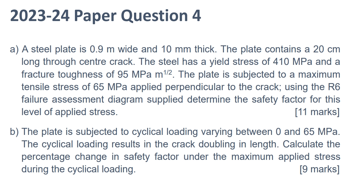
🔁 What happens to the safety factor if the crack doubles in length under cyclic loading from 0 to 65 MPa?
Redo Lr & Kr for crack length 40 cm.
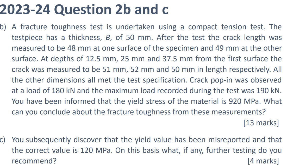
🔍 A fracture toughness test on a CT specimen (B = 50 mm) gives varied crack lengths. PQ=180 kN, Pmax=190 kN, σy=920 MPa. Is the result valid and what is the fracture toughness?
Highlight what test is being performed (E.g. Compact Tension Test)
Find parameters: W
Mean Crack Length, a (Is NOT based on the surface, as the surface is based on Plane Stress, whereas the interior is only under plane strain conditions.)
As Crack Pop, the Load , F is NOT based on the maximum load but is the LOAD AT the crack pop !
Find a/w & shape function - f(a/w) for Compact Tension Test
Calculate KQ value
VALIDITY TESTS:
Pmax/PQ < 1.1
Find smallest parameter (e.g. B)
Next calculate validity for multiple parameters of a. (BOTH AT THE SURFACE & THE CENTRE)
For the centre, keep a1 consistent for the first value of the numerator & the numerator, use first equation for the centre
For the surface, keep a1 consistent from the previous, just change the second value in the numerator & use the second equation for the surface.
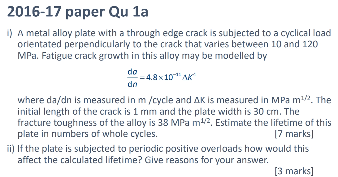
📈 Estimate the fatigue lifetime of a plate using:
Find out what type of crack = Edge or Centre
Ensure: a, initial crack length is correct value & calculate C
Rearrange & Find Critical Crack Length, using Paris Law Equation: KIC = C*max stress sqrt (pi *ac)
Now Find n:
Input delta K except for a, rearrange of dn
Integrate both sides & take out constant term
Apply limit for a (i.e. ac & ai)
Finis

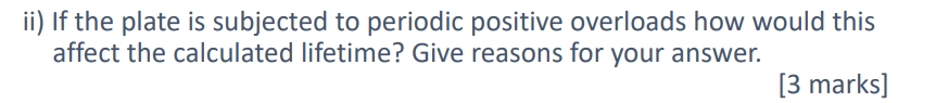
If the plate is subjected to periodic positive overloads how would this affect the calculated lifetime ?
Initial effect: Crack grows faster due to spike in ΔK\Delta KΔK
Afterward: Residual compressive stresses reduce crack growth rate
Net effect: Retardation occurs → lifetime increases

📈 Estimate the fatigue lifetime of a plate using:
Find out what type of crack = Edge or Centre
Ensure: a, initial crack length is correct value & calculate C
Rearrange & Find Critical Crack Length, using Paris Law Equation: KIC = C*max stress sqrt (pi *ac)
Now Find n:
Input delta K except for a, rearrange of dn
Integrate both sides & take out constant term
Apply limit for a (i.e. ac & ai)
Finis
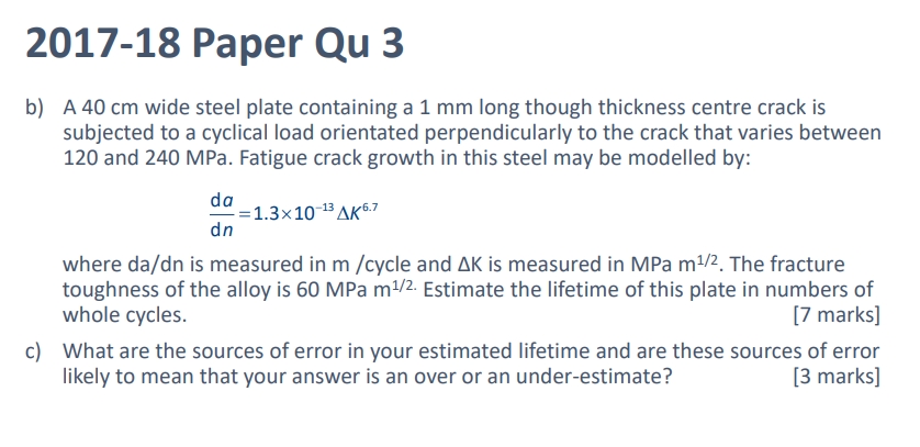
Sources of Error
Assumption of Constant Geometry Factor (C):
We usually assume approx. C≈1, but in reality it can vary as the crack grows.
Likely effect: Overestimate
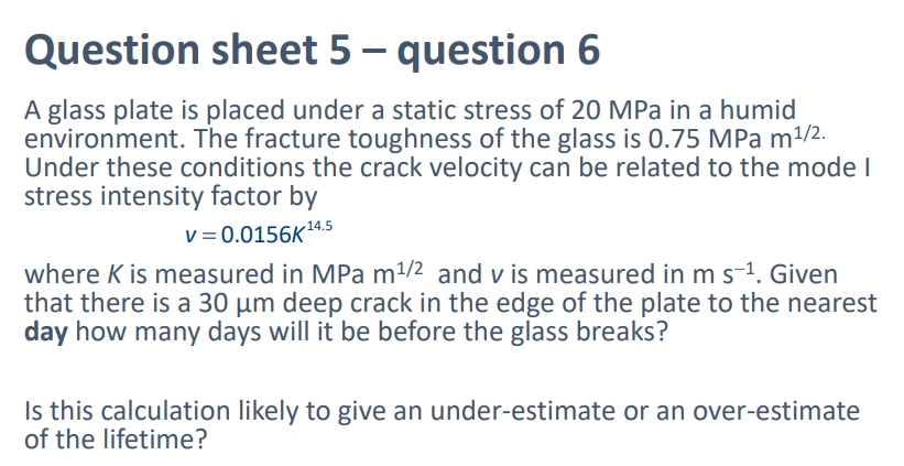
Estimate the time to failure (in days).
Then state whether this estimate is likely to be an over- or under-estimate.