Surveying 1 : Lec9 - 11
1/65
There's no tags or description
Looks like no tags are added yet.
Name | Mastery | Learn | Test | Matching | Spaced |
|---|
No study sessions yet.
66 Terms
Angles (or Angles measured)
Are classified as either horizontal or vertical.
Directions
- In surveying, are given by azimuths and bearings.
Sexagesimal System / English System
Based on degrees, minutes, and seconds
Centesimal System / French System
Based on gradians
International System (SI)
Based on radians
Angular Mil
Based on milliradians
Direction of Lines
1rev = 360° = 2π = 400grads = 6400mils
Meridian
The direction of a line is defined by a horizontal angle between the line and an arbitrary chosen reference line
Types of meridians
1. Geographic (True)
2. Magnetic
3. Grid
4. Assumed
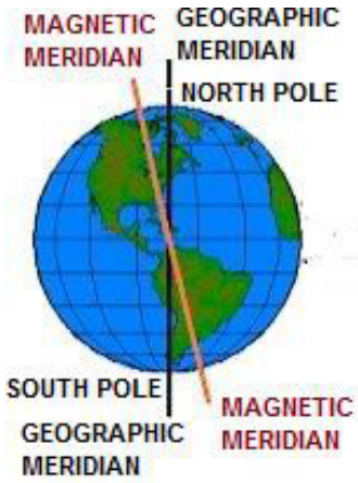
Geographic Meridian
North-south reference line that passes through a mean position of the Earth’s geographic poles.
Magnetic Meridian
Defined by a freely suspended needle that is only influenced by the Earth’s magnetic field.
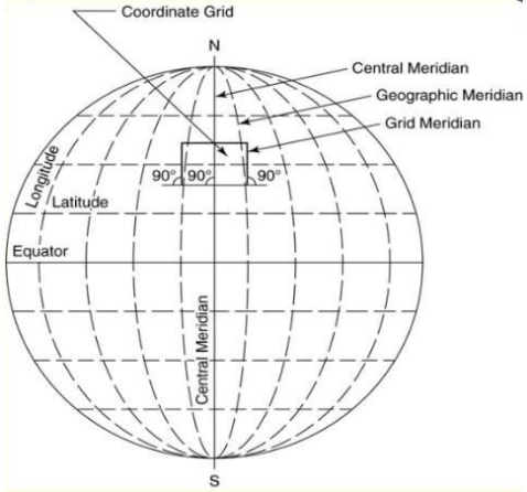
Grid Meridian
A fixed line of reference parallel to the central meridian of a system of plane rectangular coordinates.
Assumed Meridian
Established by merely assigning any arbitrary direction.
Geographic and Magnetic Meridian
Grid and Assumed Meridian
True North
North point of the true meridian.
Magnetic North
Established by means of a magnetic compass needle when there are no local attractions affecting it.
Grid North
North point which is established by lines on map which are parallel to a selected central meridian.
Assumed North
Used to portray the location of any arbitrary chosen north point.
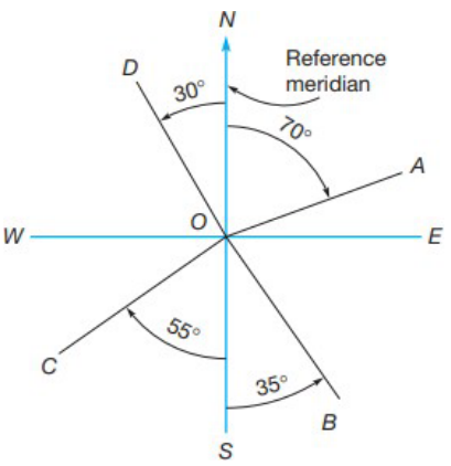
Bearings
- The acute horizontal angle between a reference meridian and the line
- Observed from either north or south toward the east or west
Bearings
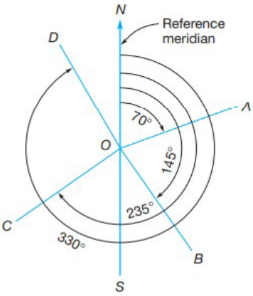
Azimuths
- Horizontal angles observed clockwise from any reference meridian
- Observed from either north or south toward the east or west
- To avoid confusion, it is necessary to state in the field notes what reference meridian applies for them and whether they are observed from north or south
Azimuths
Magnetic Declination
- Horizontal angle observed from geodetic meridian to the magnetic meridian. This is also called variation/deviation of the compass.
- Undergo continual changes because magnetic pole positions are constantly changing.
Types of variations
1. Secular Variation
2. Daily Variation
3. Annual Variation
4. Irregular Variation
Secular Variation
- Slow gradual, but unexplainable shift in the position of the Earth’s magnetic meridian over regular cycle.
- For periods of approximately 150 years, there is a gradual unexplained shift in the Earth’s magnetic fields in one direction after which a gradual shift occurs in the other direction to complete the cycle in the next 150 years.
- Can be very large and it is quite important in checking old surveys whose directions were established with a compass.
Daily Variation
- Also called diurnal variation. It is an oscillation of the compass needles through a cycle from its mean position over a 24 hour period.
- Causes a variation of as much as approximately 1/10 of 1°.
- Magnitude is still so small in comparison to the inaccuracies with which the magnetic compass can be read.
Annual Variation
Periodic swing which is less than 1min of an arc and can be neglected.
Irregular Variation
Unpredictable magnetic disturbances and storms can cause short term irregular variations of a degree or more.
Horizontal angles
Basic observations needed for determining the direction of lines.
Direction of line
Horizontal angle that the line makes with an established line of reference.
Common Horizontal angles
1. Interior angles
2. Exterior angles
3. Angles to the right
4. Deflection angle
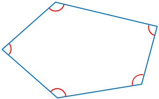
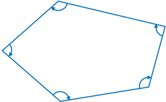
Interior angles
- Angles between adjacent lines in a closed polygon.
- Measured clockwise or counterclockwise
- σ θi = (n − 2)(180°)
Interior angles
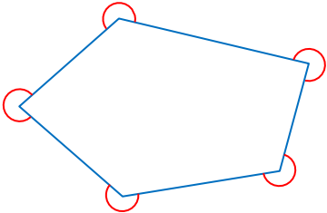
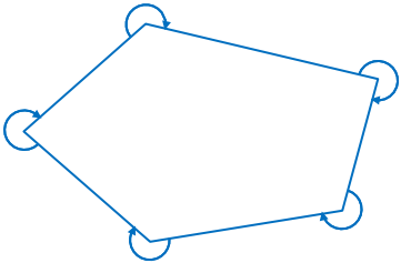
Exterior angles
- Located outside a closed polygon and are referred to as explements of interior angles
- The sum of interior and exterior angles at any station is equal to 360°.
Exterior angles
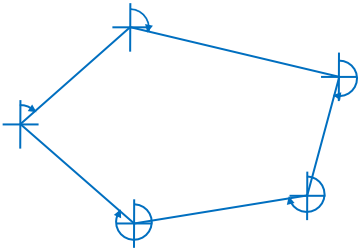
Angles to the right
Measured clockwise from the rear to the forward station and can be either interior or exterior angles of a closed traverse.
Angles to the right
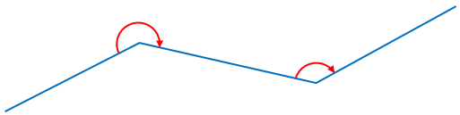
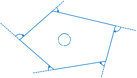
Deflection angles
- Angle between a line and the propagation of the preceding line.
- Positive for clockwise, negative for counterclockwise
- Always less than 180°
Deflection angles
Traverse
Series of lines connecting successive points whose length and directions have been determined from field measurements.
Traversing
Process of measuring lengths and directions of the lines of a traverse for the purpose of locating the position of certain points.
Traverse Station
Any temporary or permanent point of reference over which the instrumentis set up. It is usually marked by a peg or a hub. Also called angle points because an angle is usually measured at such stations.
Traverse Lines
Lines connecting traverse stations and whose lengths and directions are determined.
Interior angle traverse
Is used principally in land surveying. The usual practice in measuring interior angles is in clockwise direction.
Interior angle traverse
Angle to the right traverse
Is employed when numerous details are to be located from the traverse station. It is measured clockwise from the back line to the forward line.
Angle to the right traverse
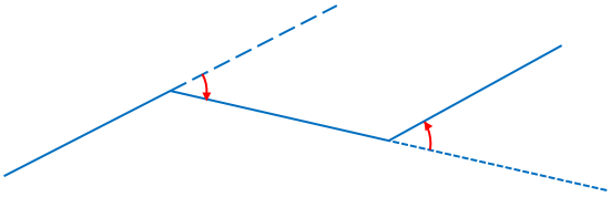
Deflection angle traverse
Is used frequently for location survey of roads and other similar surveys. The horizontal angle is measured clockwise (positive) and counter clockwise (negative).
Deflection angle traverse
Azimuth traverse
Is measured clockwise either from the north or south end of a selected reference meridian to the line.
Azimuth traverse
Compass surveying
Is one of the most basic and widely accepted practiced method of determining the relative location of points where a high degree if precision is required. Two basic operations
Open Compass Traverse
Consists of a series of lines of known lengths and magnetic bearings which are continuous but do not return to the starting point or close upon a point of known position
Closed Compass Traverse
Consists of a series of lines of known lengths and magnetic bearings which forms a closed loop, or begin and end at points whose positions have been fixed by other surveys of higher precision.
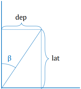
Latitude
Line projection onto the reference meridian or north-south line
Departure
Line projection onto the reference east-west line
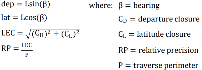
Latitude and Departure
Latitude and Departure Formulas
Traverse Adjustments
The procedure for computing the linear error of closure and applying corrections to the individual latitudes and departures
Methods of adjusting traverse
1. Compass Rule
2. Transit Rule
Compass rule
- Is based on the assumption that all lengths were measured with equal care and all angles were taken with approximately the same precision.
- The correction to be applied to the latitude (or departure) of any course is equal to the total closure in latitude (or departure) multiplied by the ratio of the length of the course to the total length or perimeter of the traverse.
- This is the most commonly used technique for adjusting traverses.
The Bowditch or Compass Rule
- Also applied a proportional adjustment but in this case, the distances between stations are used in proportion to the total distance of the traverse.
Compass rule formulas

Transit rule
- Is based on the assumption that all angular measurements are more precise than the linear measurements.
- The correction to be applied to the latitude or departure of any course is equal to the latitude or departure of the course multiplied by the ratio of the total closure in latitude or departure to the arithmetical sum of all the latitudes or departures of the traverse.
Transit rule formulas
