Nuclear Semester 2 - Lectures 5-8
1/59
There's no tags or description
Looks like no tags are added yet.
Name | Mastery | Learn | Test | Matching | Spaced | Call with Kai |
|---|
No analytics yet
Send a link to your students to track their progress
60 Terms
Define legacy waste
Waste generated during early reactor programmes in 1940’s and 1960’s
Brief history of Sellafield
One and a half square mile complex
Magnox Pile reactors and first fuel reprocessing plant during late 40s and 50s for weapons
First civil electricity from Calder Hall opened in 1956
Second gen fuel facility in 60s THORP in 90s
Describe Sellafield waste legacy
10 Magnox stations by 1966
Increase pressure on storage facilities for spent nuclear fuel
Cladding under water in silos
Fission product stored as concentrated acidic waste
Outdoor cooling ponds for spent fuel
Facility open to the elements, dust dirt algae other biomaterial, partial/full corrosion of materials, sludge formation
Describe Hanford waste legacy
Over 1600 different waste sites
Main waste are precipitated secondary products from fuel reprocessing
Over 2 million cubic meters of active sludge/effluent wastes generated between 40-80s
More stored in 150 temporary single shell tanks
Significant leaks has led to major concerns with contamination of water
Describe Le Hague and its waste
Built in 1967 to reprocess plutonium for weapons
Currently one of the worlds largest fuel reprocessing facilities
Reprocesses fuel from Europe and Japan
Plutonium turned into MOX fuel at Marcoule
Reprocessing increased in 70s and 90s
Waste generated from fuel reprocessing and related effluent treatment
Uses co-precipitation method to remove radioactive ions from liquid combined with filter media and ion exchanges
Describe the types of waste
Liquids (effluents, extraction solvents, organic residues)
Historical liquid effluent run-off into rives and oceans have been main environmental and health threats
Modern effluent treatments can handle most dissolved radioisotopes
Sludges/slurries
Precipitated salts, captured coagulated material, fuel cladding breakdown sludges
Legacy sludge waste represents the major nuclear legacy problem for UK and USA
What are the origins of legacy sludge wastes?
Fuel reprocessing
Main origin for USA legacy - varied precipitated salts and fission products from early fuel reprocessing
Continued generation at current processing facilities world wide (THORP)
Effluent treatment
At all stages of fuel cycle, effluents must be treated
Flocculated/coagulated solids with bound radionuclides from early treatments
Contaminated sand filter media/ion-exchange media from modern treatment systems
Fuel/Cladding storage
In US/UK, early high volume elemental U fuel used
Often stored long-term with fuel cladding in unsuitable silos and open ponds
Major legacy problem for the UK
Describe liquid and aerial effluent regulation
The regulation of non-radioactive discharges and disposals is the responsibility of the environmental agency and local authorities who regulate discharges under EPR 2010
Control of radioactive wastes is subject to the provisions of the environmental permit for radioactive substances
BSS 1996 relating to dose limits were incorporated into UK law
BAT(NEEC) All discharges of radioactivity are subject to the requirement to use Best Available Technique to limit radioactive discharge
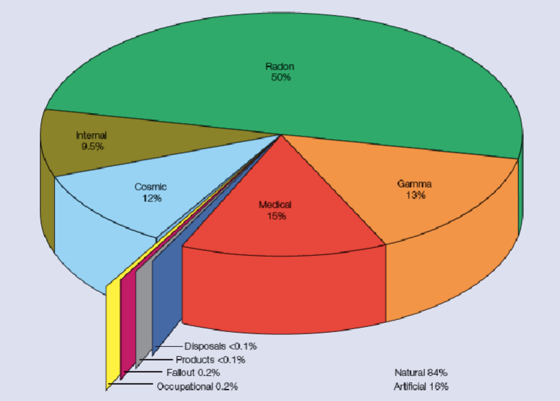
Annual dose of radiation to the public
Natural background ~84%
Medical ~15%
Average dose is around 2700 uSv of which
2230 natural
410 medical
6 occupational
6 nuclear weapon fallout
0.9 discharges and disposals
0.1 cosumer product
What are the three main processing techniques of legacy liquid effluents
Co-precipitation methods
Ion-exchange/physical adsorption
Membrane processes
What are the main mobile fission ions of concern for liquid effluents?
Caesium-137
Strontium-90
Other trace fission products (Ce, Ru, Ba, Sb)
Trace actinides
Describe the process of precipitation removal via co-precipitation reactions
Various chemical precipitation reactions exist with differing affinity for particular elements
Use co-precipitation ions to form main coagulants, as fission ions are not in highly enough concentrations to precipitate
Radioions removed by two processes
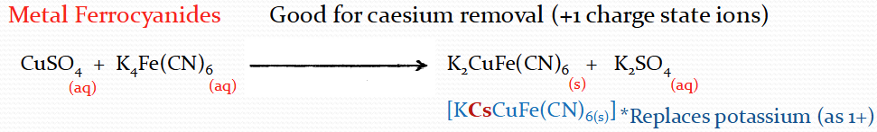
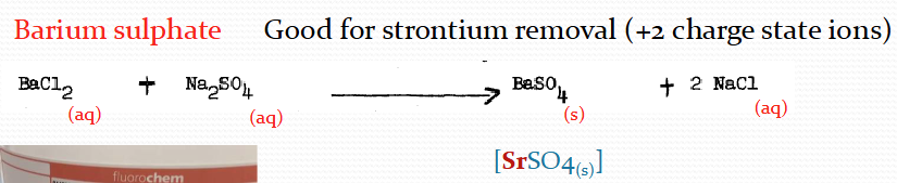
Substitute for main precip ions and precip along with main reactions
Removed via physical adsorption onto formed precip
What is good for Caesium removal?
What is good for Strontium removal?
What is good for Strontium and actinide removal?
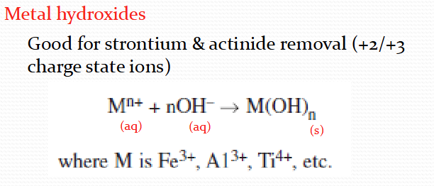
Describe the Ferric sulphate coagulants
Iron salts
Need to pre-treat with quicklime and make pH neutral
Main processes at EARP for actinide removal
Forms highly voluminous sludge relatively easy to remove via traditional separation techniques
Downsides - quite pH dependent, must neutralise first

Pros of co-precipitation methods
Work well in high salt and variable environments
Often do not have high selectivity
All require further solid-liquid separation processes to produce clean water
Low relative decontamination factors
Descirbe Ion-exchange as a method of processing liquid effluents
Common in nuclear industry to use natural zeolite material
Standard is clinoptilolite
Zeolites have complex crystal structure with interstitial gap sizes that can trap ions at high capacity
Zeolites also have large non-specific surface adsorption sites, hence removal is adsorption and exchange
Describe the IOX comparison for clinoptilolite
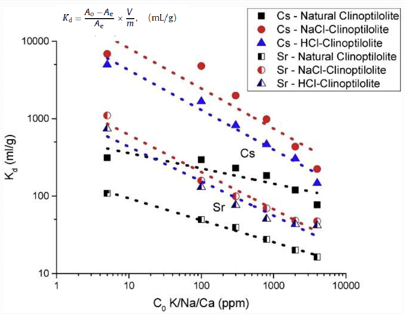
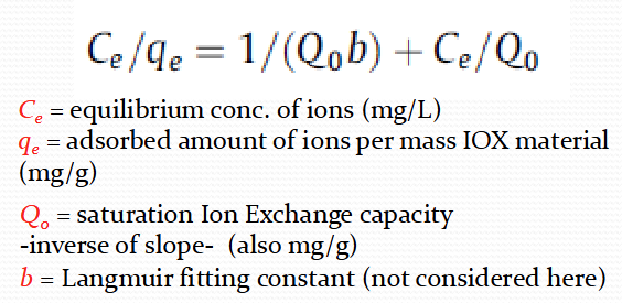
What is the langmuir isotherm equation
Cs+ - Qo = 214.1
Sr2+ - Qo = 98.13
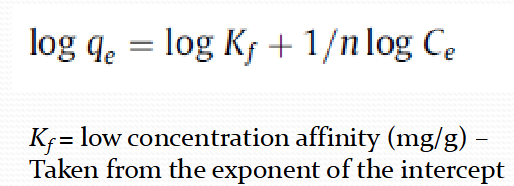
What is the Freundlich isotherm equation
Cs+ - n = 2.529, Kf = 6.897
Sr2+ - n = 2.893, Kf = 7.566
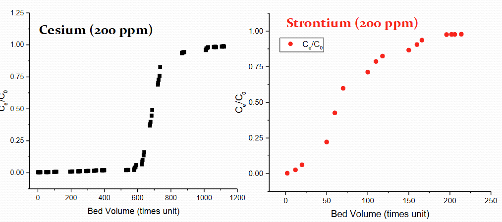
Describe IOX column breakthrough kinetics
Experiments in column tests can be also used to estimate ion-exchange capacity, but also breakthrough kinetics
Normally, small scale columns are used and the ratio of the time outlet concentration (Ce) is measured against the initial concentration (Co) over time
Describe same ppm but one is Cs and one is Sr graph for IOX breakthrough
30 mins column residence time
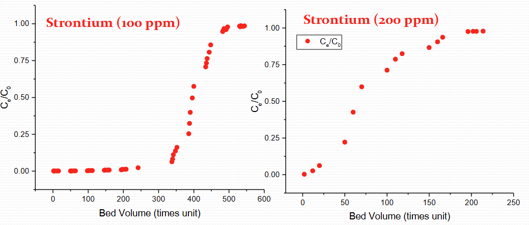
Describe the same element but different ppm for 30 min residence time for IOX breakthrough
100 vs 200 ppm
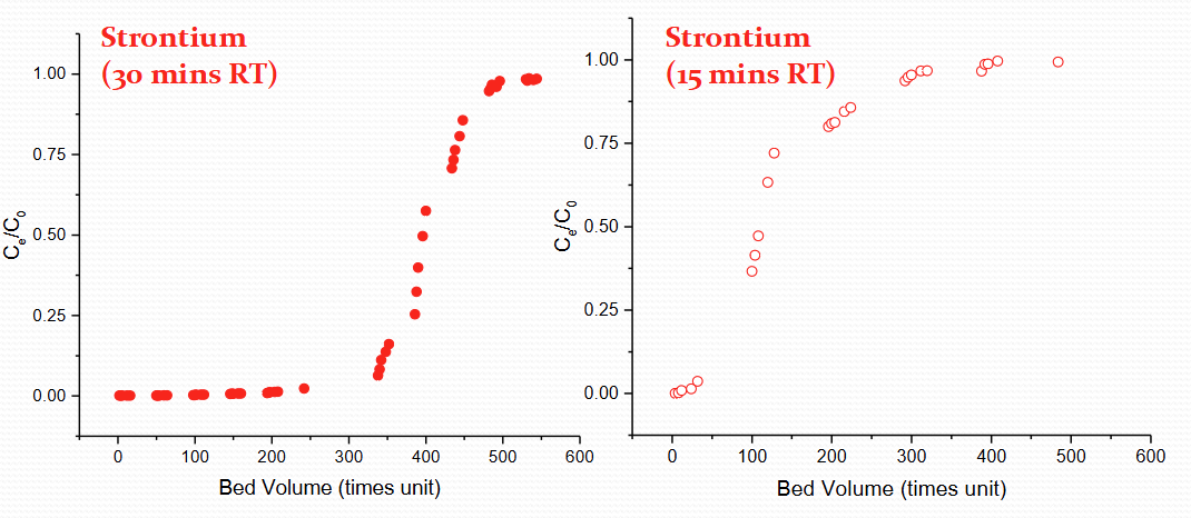
Describe same element and same ppm but different residence time for IOX breakthrough
30 min vs 15 min
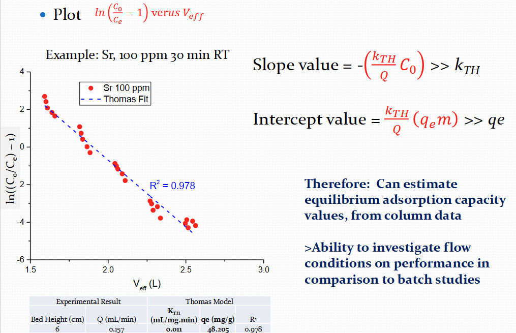
What is the Thomas model for IOX breakthrough
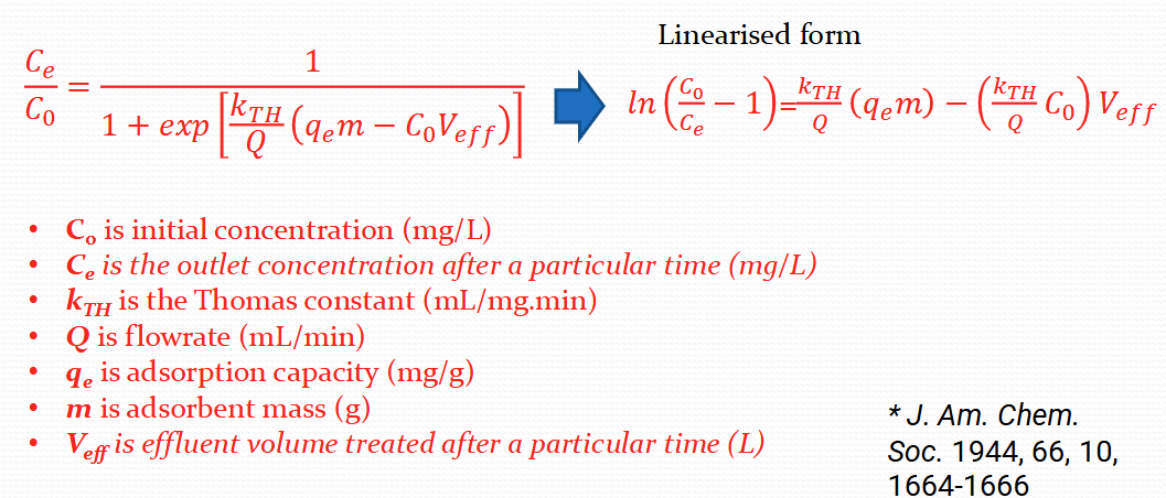
For the Thomas model, what is the plot, slope value and intercept value?
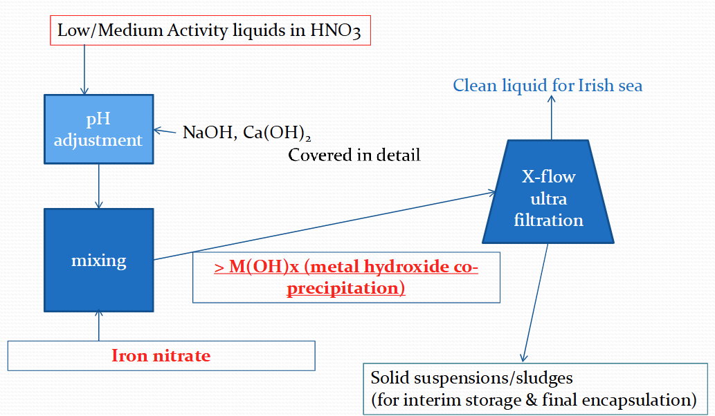
What is an enhanced actinide removal plant?
Commissioned in 1994 to treat medium active concentrates and low active effluents with high levels of Fe
pH adjustment - to 7-8 which precipitates Fe as Fe(OH)3 floc
Cross flow filtration in 2 stages with ultra filters - final solids content is 50-100g/L
Iron hydroxide co-precipitates with strontium and other fission products
Powdered IOX can be added in batch to remove any caesium
Complex aggregate formed
Describe a flow chart for Sellafield’s enhanced act rec plant (EARP)
Describe a cartridge filter design for EARP
Cross flow ultrafiltration
Can remove particles in the range of 0.001 micro-m to 0.1 micro-m
Filter median is usually paper or other fibrous materials reinforced with a metal mesh
What is a SIXEP?
Site Ion Exchange Effluent Treatment Plant
Commissioned in 1985 to treat Magnox fuel pond liquors
Pressure filtration - sand bed filters to remove solids (Mg OH sludge)
pH adjustment
IOX - inorganic exchanged (clinoptilolite) giving DFs of up to 500 for Sr 90 and 2000 for Cs 137
Describe sand bed filter for liquid effluents
Macroporous
Can remove particles >10 micrometres
Ion exchange
Media chosen for specific selectivity
Finite IOX capacity
Reduction in IOX efficiency over time
Instantaneous DF could reduce from 2000 to <10
bed replacement
Describe the Hanford tank side caesium removal system (TSCR) project
Currently commissioning microfilter and IOX system
Mobile station wil sit on the tank farms and remove elevated levels of Cs+ from low activity tank liquours
Minimum of 643k litres of waste from tanks will be treated and at least 3.7 × 10^15 Bq of 137Cs will be removed in this phase
Second phase will process up to 18.9 × 10³ m³ (5 Mgal) of waste feed
IOX column uses crystalline silicotitanate (CST) IX median produced by UOP Honeywell
Initial Steel membrane nanofilter, to ensure no solids past the IOX
Describe the focus on Fukushima for treatment
Treatment of highly radioactive effluent from reactor cooling waters (mainly sea water)
Multiple treatment systems set-up in stages
Initial process was co-precipitation
Main process was to remove Cs
Metal ferrocyanide process
Low Sr removal and high level of secondary wastes meant new long term plans required
Multistage co-precipitation and IOX plant installed (Toshiba, Kurion)
Initial stage uses Honeywell IOX materials for enhanced Cs removal
New high performance multinuclide removal usits uses iron hydroxide and carbonate co-precipitation and new proprietary IOX
What is SARRY?
Simplified active water recovery system - enhanced Cs removal (IOX)
What is ALPS?
Multinuclide removal facility - Secondary precipitation and IOX system for remaining radioactivity removal
How will legacy sludges be processed? (basic)
Sludge wastes must be transferred, processed and categorised before being sufficiently treated to allow cementation
Sludge must be thickened to allow proper binding with cement
As sludges are highly heterogeneous, very difficult to product a cement recipe that will work
Both sludge composition and water content almost impossible to fully categorise
Another option is to mimic HLW processing, completely drying sludge to powder to allow easier cementation. Very energy intensive and requires off gas treatments
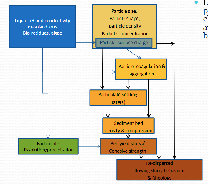
Why are sludges difficult to process?
Complex multiphase, multicomponent systems
Creates very heterogeneous sludges with a large envelope of physical and chemical properties
A lack of well defined historical characterisation data
Difficult to fully understand what is really present
Site toxicology and radiology greatly limits sampling
Long term environmental changes
Sludges constantly aging and changing
Open air environments leads to potential high biological and organic contamination
Explain Inline cementation for sludge processing
Developed waste route, based on a wet-sludge mix being cemented
Wastes relatively ell characterised, as generally have been independently contained and separated
Different cementation routes must be designed for different sludge types
Briefly describe the 8 steps of the disposing of Hanford’s nuclear waste
1 - Liquid radioactive waste will be pumped from underground storage tanks into the low activity waste pretreatment facility
2 - Low activity waste pretreatment facility reduces the level of Cs and solids in the liquid waste, then piped underground to the vitrification facility
3 - The waste pipe runs into a manifold over a below-ground drain tank before reaching teh vitri facility. Drain tank allows transfer pipes to be gravity flushed after each waste transfer
4 - Waste is piped into concentrate receipt tank, each transfer is 9000 gal
5 - Waste is pumped into a mixing tank and combines with silica and other glass forming material
6 - The silica mixed waste is pumped into one of the two melters and heated to 21000 degrees farenheit overall several days forming molten glass
7 - Molten glass is poured into canisters, glass is cooled for several days until solid
8 - Canisters are sealed and exteriors are decontaminated, making them ready for permanent disposal
Sludge issues at Sellafield
More than 90% of the nuclear hazard potential on the site
22% of all site programmes
35% of the total site costs during next 4 years
77% of the major project costs during the next 4 years
Describe Magnox Swarf Storage Silos (MSSS)
Original silos for de-canned Magnox fuel canister swarf
A number of very large waste deposits totaling 10000-15000
Currently preparing for emptying, as part of risk reduction programme
20+ year programme to extract MSSS wastes using overhead grabs
Waste to be filled in 3m³ boxes as interim storage pending final disposal
Chronic corrosion of magnesium based wastes presenting 2 major issues:
Volume expansion
Pressurisation
Procurement cost anticipated to be >£250m
What is an FGMFP?
Main storage for fuel and cladding during civil power gen in 1960s
Most fuel decladding in MSSS, but some 1500m cubed remains
Cladding broke down into Mg (OH)2 based sludge
Sludge retrieval for sludge packaging plant
Issues
High and variable yield stress
Large particle size distribution
Open air pond - miscellaneous organic activity
What is a PFSP?
Pile fuel storage pond
Made for temporary storage of windscale pile fuel for processing
Waste consists of fuel, sludge and other debri due to open air pond
Sludge is low volume and yield stress
However very high organic and algal content with very complex behaviour
Complex heterogeneous aggregates
Current plan is local sludge treatment plan
Sludge at 10% wt in corral transferred to buffer tank
20% seen as max safe limit
Benefit - no need for further thickeners or dewatering
Cost - All efforts to consolidate sludge in corral only to tilute
What are HASTS?
Highly active storage tanks
Impinging jet buffer tanks to hold highly active liquor by-product from THORP fuel reprocessing
Mainly dissolved species - however precipitated fission products of Cs phosphomolybdate (CPM) and zirconium molybdate (ZM)
How do we categorise sludge systems?
Critical process zones : Zone 1
Usually use form of liquid jets or eductors
Critical to characterise jet particle - bed interaction
Consolidated bed eroded through high jet velocity pressures and shear
Eroded particulates must be mobilised sufficiently to allow transport
Erosion depends on YS, particle properties and jet properties
Critical to understand jet dilution on sludge
Most sludge transported at up to 5 vol%
High dilution = High volume of effluent treatment
Give an example of zone 1 in critical process zones
HASTS (High active storage tanks)
Erosion and mobilisation
Bed critical shear stress (Tc)
Particle cohesion, size, density, agrregation
Particulate re-settling and transport
Size and density
Concentration
Suspension rheology
Turbulent interaction with jets and air-lifts
Normalise erosion
Can consider erosion either
A momentum/pressure force acting on single particles
A shear force acing on a semi-solid homogeneous fluid of a given critical shear strength
Equation for erosion from particle basis
Equation for Final erosion length or radius
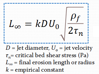
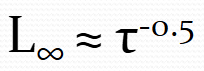
Critical relationship between sheer stress and erosion length
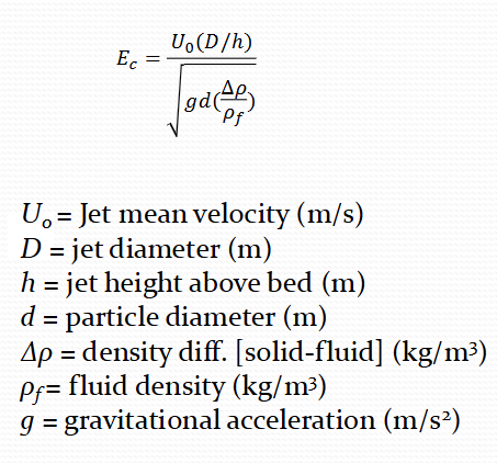
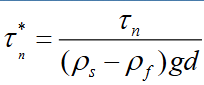
Equation for dimensionless critical bed shear stress
Describe zone 2 of the critical process zones
Sludge transport
Critical balance between the fluid flow properties and particle properties
Require flow velocity to be high enough to maintain particles in suspension
If too great, the level of shear may break down the waste aggregates and structurally change the particle properties
Normally consider balance of reynolds number (flow) and Froude number (particle) properties to understand critical deposition velocities
Describe zone 2 expanded theory
Critical to characterise particle sedimentation re-suspension in pipes
Very complex turbulent interactions
High particle volume = more energy to suspend but increased hindered settling interactions
Main variables to consider
Particle properties : size (d), fluid density (ro f), particle density (ro s), and concentration (phi)
Flow properties: critical flow velocity (Uc), kinematic viscosity (v), gravity (g)
Therefore: number of variables = 7, number of dimensions = 3, number of dimensionless numbers to describe = 4
Consider density ratio S = ps/pf as one parameter
Reynolds number equation

Describe zone 3 of the critical process zones
Sludge separation
Sludges will separate and consolidate in storage
Some form of separation will be required to thicken sludge and give consistent mixture to waste treatment plant (WTP)
Sludges will change behaviour from that in ponds and silos due to pumping and transportation, hence prediction is difficult
HASTS - settling of CPM, ZM, and ZMCA - critical to evaluate the rate of using jets for erosion
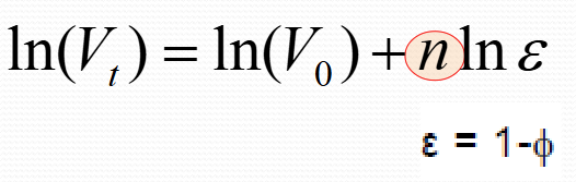
What is the Richard-zaki equation?
CPM - faster settling in low concs but hinders more as conc increases
ZM - sloer low conc settling, but does not hinder as much with conc increase
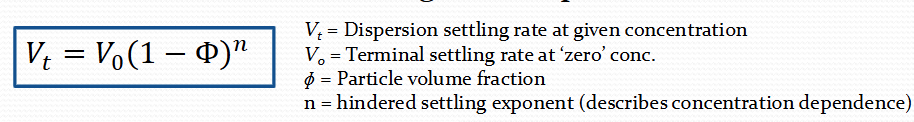
Richard-zaki in log form