CT: Data Acquisition Methods (2)
0.0(0)
Card Sorting
1/49
Earn XP
Last updated 9:19 PM on 4/4/23
Name | Mastery | Learn | Test | Matching | Spaced | Call with Kai |
|---|
No analytics yet
Send a link to your students to track their progress
50 Terms
1
New cards
Scan Field of View (SFOV)
**Circular region within the gantry** from which the transmission measurements are recorded during scanning
Determines how many detector cells are collecting data
Determines how many detector cells are collecting data
2
New cards
T
T/F: There are usually a few fixed choices for SFOV in the system. \[ Small & Large \]
3
New cards
Display Field of View (DFOV)
Circular region that determines how much of the collected data is **used to create an image.**
4
New cards
Localizer Scan
Preliminary step before taking a cross-sectional image.
Image acquired is similar with a conventional radiographic projection (2D)
Image acquired is similar with a conventional radiographic projection (2D)
5
New cards
T
T/F: Tube and gantry remain stationary during a localizer scan.
6
New cards
(Z D EF— MR)
Determines Z axis coverage
Selecting DFOV and image center
Exposure Factors for CT
Identify mispositioning
Serves as a reference image
Determines Z axis coverage
Selecting DFOV and image center
Exposure Factors for CT
Identify mispositioning
Serves as a reference image
5 purposes of a localizer scan.
7
New cards
perpendicular
parallel
parallel
The images generated using the step- and-shoot method were — to Z-axis and -- to every other slice
8
New cards
Clustering
A term used when more than 1 scan can be taken in a single breath-hold (Step-and-Shoot Scan)
9
New cards
Good
Good/Bad: Spatial Resolution in a Step-and-Shoot image
10
New cards
Contiguous and non-contiguous slices
2 kinds of image acquisition in a step-and-shoot scanning method.
11
New cards
Cine
**Axial** scans set to **repeat scans at the same slice location**.
12
New cards
Interscan Delay
4 Limitations of Step-and Shoot method
Longer examination time; patient is at the table with no data being acquired.
Longer examination time; patient is at the table with no data being acquired.
13
New cards
misregistration
4 Limitations of Step-and Shoot method
Omitted anatomy due to inconsistent patient respiration.
Omitted anatomy due to inconsistent patient respiration.
14
New cards
Stairstep
4 Limitations of Step-and Shoot method
Inaccurate generation of 3D or reformatted images producing — artifact.
Inaccurate generation of 3D or reformatted images producing — artifact.
15
New cards
Contrast Issues
4 Limitations of Step-and Shoot method
only a few slices seen with maximum contrast
only a few slices seen with maximum contrast
16
New cards
Detector
Refers to a **single element** or type of detector used in a CT system.
17
New cards
Detector Array
refers to the **collection of detector elements** used in a CT system
18
New cards
Reference Detectors
elements in a detector array that **measure non- attenuated radiation**; this assists with calibration and artifact-reduction
19
New cards
Single Detector Row System (SDRS)
contained many **detector** elements **aligned in a single row**
• Many detectors along the X-axis
• One row in the Z-axis (1D in z-axis)
• Many detectors along the X-axis
• One row in the Z-axis (1D in z-axis)
20
New cards
Beam Collimation
What determines the slice thickness in SDRS?
21
New cards
patient experience
workflow
image with contrast
workflow
image with contrast
Development of reduced scan times were made for (3)
22
New cards
Slip rings and MDRS (multiple detector row system)
2 main drivers of scan time reduction
23
New cards
MDRS
are a **two-dimensional arrangement of detector arrays** where many **parallel arrays are aligned in the Z-axis**
• **Multiple slices can be acquired for each rotation** of the x-ray tube and detector
• **Multiple slices can be acquired for each rotation** of the x-ray tube and detector
24
New cards
Detector Electronics
responsible for **digitizing the signals from the detectors** **before** they are sent to the computer for **processing.**
25
New cards
Switches
Data acquisition channels **(DAC)** are coupled to the multiple detector array by what?
26
New cards
Switches
Responsible for **grouping the signals** from individual detector elements and sending them to DAC
27
New cards
1 Slice
Grouped signals from the switches go to a corresponding DAC; **1 DAC corresponds to what?**
28
New cards
Rows
simply refers to the **number of detector elements** lined up in the Z-axis
29
New cards
slice
refers to **how many slices may be obtained for each rotation** of the gantry; this is **determined by the number of data acquisition channels**
30
New cards
binning
__**combining**__ **various detector elements electronically** to produce the desired slice thickness required for the examination
31
New cards
Beam width and detector array configuration
In MDRS, how is slice thickness determined?
32
New cards
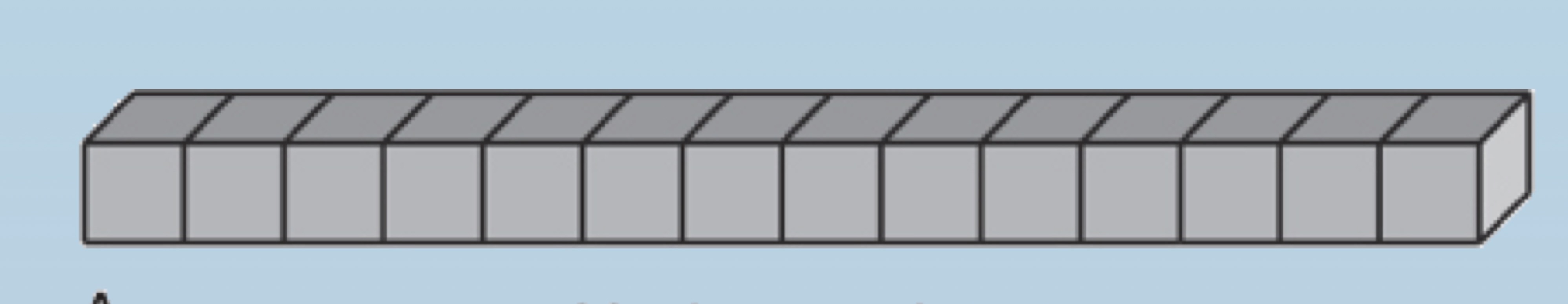
Fixed
matrix
Uniform
matrix
Uniform
Variations in MDRS (arrangement)
Detector elements **arranged in parallel rows of equal size**
Detector elements **arranged in parallel rows of equal size**
33
New cards
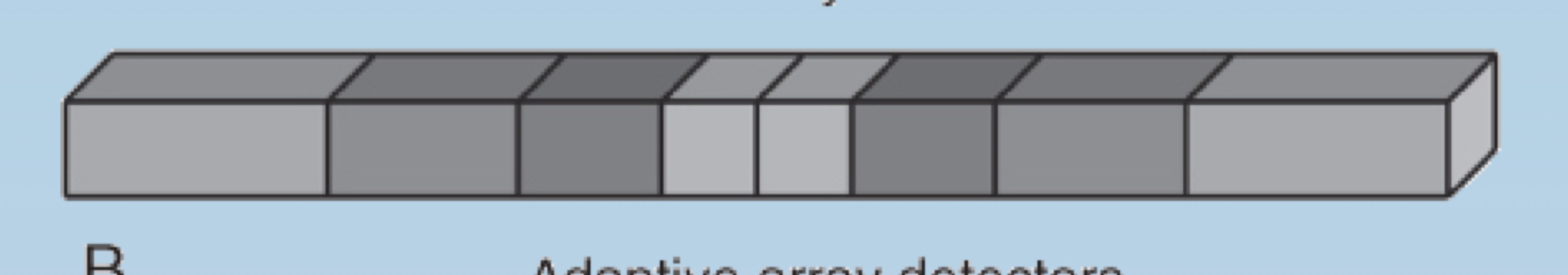
adaptive
non-uniform
hybrid
non-uniform
hybrid
Variations in MDRS (arrangement)
DEL arranged in parallel rows of variable size
DEL arranged in parallel rows of variable size
34
New cards
Isotropic
When the **slice thickness is equal to the pixel size**, all dimensions of the voxel are equal→dataset is —.
35
New cards
Good
Good/Bad: Spatial Resolution in an isotropic image.
36
New cards
F
T/F: Scanning time and radiation dose is reduced when acquiring an **isotropic image**
37
New cards
Helical Scan
the x-ray tube, detector and table **are in motion throughout** the entire data acquisition process
• The result is a volume of data instead of separate individual slices.
• The result is a volume of data instead of separate individual slices.
38
New cards
Slip rings
Allowed the continuous rotation of the x-ray tube and detectors; eliminating long cables.
Reduced interscan delay.
Reduced interscan delay.
39
New cards
Increased mAs
One limitation of helical scanning is heat due to continuous exposure and —.
40
New cards
Helical Interpolation
The principal technique used to remove blur and slant in a helical image.
41
New cards
360 LI
An algorithm that interpolates a planar slice using data points measured 360 degrees apart.
42
New cards
180 LI
uses data points **closer to planar slice** to be interpolated
• produces a **sharper** **helical image** (however, with increased **noise**)
• produces a **sharper** **helical image** (however, with increased **noise**)
43
New cards
Slice thickness blooming
The outcome of this selection is not precise as the true size of the slice thickness is often slightly larger than the size selected
caused by:
* interpolation technique
* table speed
* detector width
caused by:
* interpolation technique
* table speed
* detector width
44
New cards
Pitch
is defined as the **travel distance of the CT table** per 360° rotation of the x-ray tube, **divided by the x-ray beam collimation width**
\
a ratio that compares how much of the table enters the gantry to how wide the beam is in the Z-axis (for each rotation of the x-ray tube)
\
a ratio that compares how much of the table enters the gantry to how wide the beam is in the Z-axis (for each rotation of the x-ray tube)
45
New cards
1
When the amount of table that enters the gantry is equal to the beam width, the pitch is equal to?
46
New cards
increases
**SDRS: Pitch**
• When we increase the amount of table entering the gantry but keep the slice thickness the same, the pitch
• When we increase the amount of table entering the gantry but keep the slice thickness the same, the pitch
47
New cards
decreases
**SDRS: Pitch**
When we decreases the amount of table entering the gantry but keep the slice thickness the same, the pitch—.
When we decreases the amount of table entering the gantry but keep the slice thickness the same, the pitch—.
48
New cards
high pitch
high/low pitch: The spiral is extended and stretched and the slant present in the helical image increases
49
New cards
50
New cards
Detector element
The smallest slice width available is determined by