PHYS C1
1/45
There's no tags or description
Looks like no tags are added yet.
Name | Mastery | Learn | Test | Matching | Spaced | Call with Kai |
|---|
No analytics yet
Send a link to your students to track their progress
46 Terms
Amplitude
A, m
Maximum displacement of any point in medium from its rest position
Peak-to-peak amplitude
maximum displacement of rarefaction to maximum displacement of compression
= 2A
Period
T, s
time taken for a particle in medium to complete one cycle
Wavelength
λ, m
distance between points that are in phase
Frequency
(f, Hz)
number of cycles that each particle undergoes per unit time
directly proportional to viscosity (internal friction) and thus absorption
low f has higher penetrating power
Wave Equations
f = 1 / T
v = fλ
Ultrasound frequency
above human hearing (>20 kHz)
1 to 50 MHz
MI Typical frequency
1 MHz to 40 MHz
Low f purpose
greater penetration for large/deep structures as longer wavelength reduces attenuation
High f purpose
better resolution for superficial tissues (skin, eyes) as smaller structures detected without scattering
Bulk Modulus
K, Pa
Medium’s resistance to compression (stiffness)
High Bulk Modulus Explanation
High K (bones):
doesn’t deform easily under pressure
strengthens the elastic restoring force
propagating the wave
increase velocity of sound
Low Bulk Modulus Features
Low K (soft tissue):
loosely packed particles
overshoot and oscillate
less efficient energy transfer
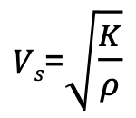
Velocity of Sound Formula
K = bulk modulus
ρ = density of medium (kg/m³)
Velocity of sound in fat, tissue, and muscle
Fat - 1459m/s
Tissue - 1540m/s
Muscle - 1580m/s
dB formula + def
dB: intensity of sound
dB = 10 log10 (I2 / I1)
where I1 = initial intensity
dB/I + A link
I = A²
So bringing power to front of log: dB= 10 log10 ((A2/A1)²) = 20 log10 (A2 / A1)
Absorption Def
wave’s energy being lost as heat due to viscosity (internal friction) of medium’s particles (directly proportional to frequency)
most prevalent in bone
reduces penetration power
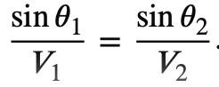
Snell’s law
Specular reflection
angle i = angle r
produces brightest echo
Diffuse Reflection
sound beam hits interface at different incidence angles due to an uneven surface, causing numerous angles of reflection
Rayleigh Scattering
multi-directional reflection
scatter intensity dependent on frequency
darkest/weakest echo
Stochastic/probabilistic scattering
describes randomness of scatter directions
scatter pattern depends on orientation of areas of boundary relative to incident beam
speckled pattern created by constructive and destructive interference of scattered waves
Reflection def + Rules
Allows for visualisation of soft tissue structures in ultrasounds
If area of boundary is:
>λ (organ) - Specular reflection
<λ (red blood cells) - Rayleigh Scattering
=λ (internal regions of organ) - Stochastic/probabilistic scattering
Attenuation Def + Causes
Decrease in intensity/amplitude of wave with distance, reduces wave’s penetration power
Result of:
Spreading wavefronts over an increasingly large area
Absorption
Redirection of wave via reflection, refraction, diffraction, scattering
Refraction Def + Rules
Change in direction of a transmitted wave at a boundary interface caused by the change in wave’s velocity
If beam strikes interface at 90°, beam is partially reflected with rest transmitted and no refraction
V increases bends away normal
Artefacts
caused by refraction and creates:
distortion of object in monitor
appearance of object at wrong location
shadowing
Acoustic Impedance
(Z, kg/m²s = rayl)
measure of a medium’s resistance to the propagation of ultrasound wave
Z = ρc
difference in acoustic impedance at boundary interface causes reflection (echo) thus visualization of soft tissue structures
Link between Z and echo strength
larger the diff in Z, the more sound will be reflected (stronger echo)
Which spaces does sonography not produce good images of and why?
Since bone’s Z is much higher than soft tissue’s, nearly all sound is reflected at bone’s surface with little penetrating, making it unable to visualize deeper structures
Same for air (so lungs) as Z much lower than soft tissue
Coupling Jel
Applied over skin on area to be scanned, creating a more homogeneous medium by filling the air gap between transducer and skin
Because gel has a more similar acoustic impedance to skin than air, it reduces the number of sound waves reflected back to transducer without entering body
Also reduces friction
Pulse Echo Technique
A fraction of the incident beam reflected back to transducer at each interface before next pulse is applied
Echo Ranging
Measure of time taken for reflected beam (echo) to return to transducer
Used to determine depth of interface
d=vt/2
Piezoelectric Effect
pressure electric effect
used by transducer to convert between electrical signals and ultrasonic energy
Piezoelectric Crystals
Commonly lead zirconate titanate (PZT)
Each molecule has dipole, restricting their ability to move in the crystalline structure unless heated above Curie temp
Alignment Plates
Pair of charged plates across a material
-ve dipole region points to positive plate and vice versa
Ensure molecules in crystals remain parallel and correctly spaced for beam steering and focusing
Conducting Plates
placed on opposite faces of crystal and voltage spike is applied
AC current causes molecules to twist in opposite direction when polarity is reversed (electric field changes direction)
Movement causes contraction and expansion of crystals
Mechanical Vibration
Contraction and expansion of crystals provides mechanical vibration of molecules, creating compressions (high density areas) and rarefactions (low density areas) of pressure wave
Dampening/Backing Block
Shortens the time the crystal vibrates (thus pulse length) after the current input is gone, allowing transducer to effectively detect echoes to provide better axial resolution
Also decreases ultrasound energy sent backwards and laterally, reducing waste
Matching Layer
material with an intermediate acoustic impedance to reduce reflection at skin-crystal interface
Located between crystals and coupling gel
Increased efficiency
A(amplitude)-Mode
Simplest
Ophthalmology applications
Uses echo-ranging principle (time indicates depth)
Signal amplitude shown as peak on horizontal timeline
Spike height proportional to echo intensity
Time Gain Compensation Def
User controlled to increase amplitude of deeper echoes (which underwent more attenuation) so series of pulses from equally reflective interfaces have similar amplitude
How do users control Time Gain Compensation?
Inital/delay/slope - for a set time (delay), all echoes amplified by same amount (initial gain). After delay, gain increases with respect to time (slope) as deeper echoes return, until some maximum fixed gain is reached for the deepest echoes.
Segmented - sliding bar used to control gain for each depth range
B-Mode (brightness modulation, 2D)
Converts spikes to brightness-modulated dots
Real-time 2D imaging of body cross sections
Dot location depends on time for echo to return and direction its returned from
High intensity echoes = High peaks = Bright dot
Real-Time Imaging
Series of still shots viewed rapidly one after another to depict motion
Freeze frame - ability to pause on one shot
Transducer beam points in one direction (line of sight) at a time, all echoes assumed to originate from centre of this to collect a single line, line of sight then slightly moved to collect another line, gaps between lines are filled electronically
Doppler Ultrasound
Echoes frequency fluctuates depending on whether they are moving towards or away from transducer
Red = blood flowing towards, Blue = blood flowing away
Density of colour shows speed of flow