3.2. Axial flight
1/60
There's no tags or description
Looks like no tags are added yet.
Name | Mastery | Learn | Test | Matching | Spaced | Call with Kai |
|---|
No analytics yet
Send a link to your students to track their progress
61 Terms
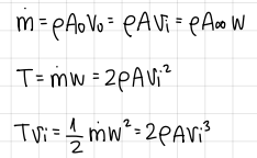
conservation laws formulas (axial flight)
formulas
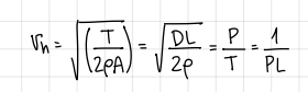
formula for the induced velocity at the rotor disk in hover
formula
we need to put 10kg in hover. which rotor do you choose?
the biggest one
how can one relate useful data across different scales? e.g. data from a scale model test in a wind tunnel to a full scale component?
Buckingham-Pi theorem
based on dimensional homogeneity
# of dimensional terms = # of independent variables - # of fundamental dimensions
choice of repeating variables is not unique → suggested choice for fluid dynamic analyses
length, scale, kinematic variable and dynamic variable
considering rotor flow:
five variables: v_i, v_tip=Omega*R, rho, T, A=pi*R²
three fundamental dimensions: mass, length and time
rotor coefficents: names and formulas
thrust coef
power coef
torque coef
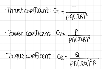
non-dimensional coefficents formulas (rotor coefficents)
formulas
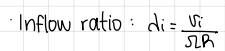
inflow ratio formula
formula
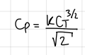
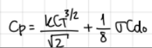
development and formula to relate power coefficent to thrust coefficent
formula

experimental observations:
experimental data is positively offset from momentum theory prediction
higher “slope” observed in experimental data at high thrust coefficents
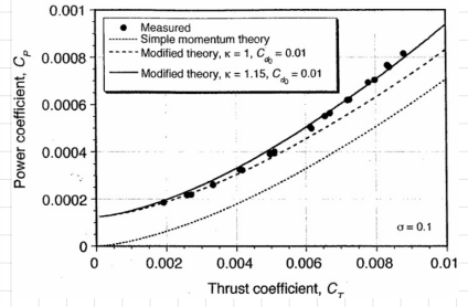
regarding the higher “slope” observed in experimental data at high thrust coefficents, how do you correct it?
with the induced power factor
estimating the profile power
induced power factor:
symbol
characteristics
formula
k
characteristics
non-uniform flow
tip losses
wake swirl
finite number of blades
formula
how to estimate/model k?
extract from experimental data
advanced rotor aero models (BEMT, etc.)
what do we need to do to estimate the profile power? formulas
consider the real form of a rotor
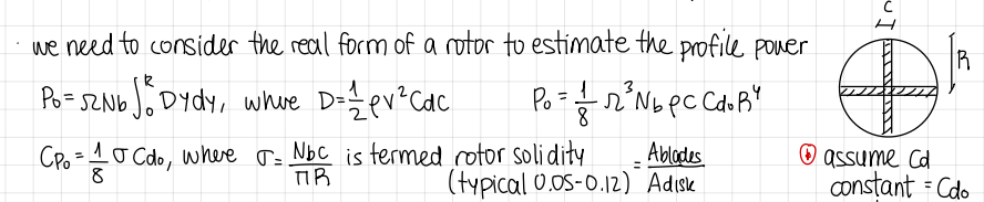
how to estimate/model Cd0?
extract from experimental data
CDF
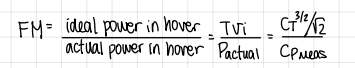
what if the required power is normalized by the ideal predicted power?
figure of merit:
formula
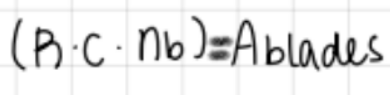
formula for area of blades
formula
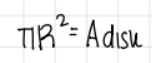
formula for area of disk
formula
how do you estimate k and Cd0 from experiments?
with linearization
estimating k and Cd0 from experiments: linearization → development
development
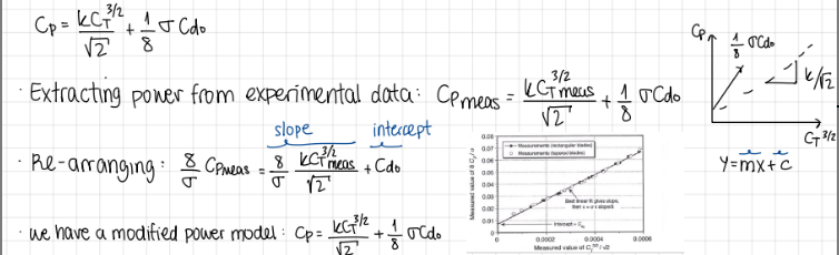
modified power model formula
formula
is power loading dimensional?
yes
what is the mathematical objective regarding rotor efficiency?
to express efficiencies as non-dimensional coefficents
figure of merit formula
formula
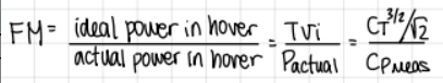
what is figure of merit?
a non-dimensional measure of efficiency in hover
maximum value of FM? (and k)
0.86 (1.15)
two procedures regarding efficiency:
procedures

what is the FM value for most rotors?
between 0.7 and 0.8
what implies if FM is lower than 0.7
that the rotor has been optimized for non-hover conditions
what happens at low c_T?
profile power dominates
what happens at high c_T?
induced power dominates
an asymptote is expected at 1/l
profile losses begin to dominate again (stall)
FM formula depending on profile and induced power
formula

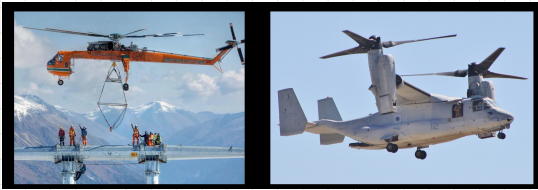
can we compare the rotors of these two rotorcrafts using FM?
No. Figure of Merit compares hover aerodynamic efficiency, not mission roles or operational purpose
FM is a valid measure to compare rotors only at the same (or very similar) DL!
alternative formulation of FM
formula
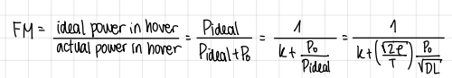
what happens if FM (Figure of Merit) is a function of DL (Disk Loading)?
it’s possible to “manipulate” FM values by only increasing DL
this will increase the induced power consumption compared to the profile power
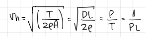
it is sought to ___ the ___ to produce a certain thrust, i.e. the ratio P/T
v_h formula
minimize DL, and consequently, ___ → this means…
minimize, power
v_i, a low rotor tip speed
how do we decide on a rotor tip speed?
set by the lowest speed that still satisfies noise, Mach and structural limits
can we optimize rotor size once a tip speed is selected?
yes. choose rotor radius to minimize disk loading while meeting thrust and design constraints
development for minimization formulation
development
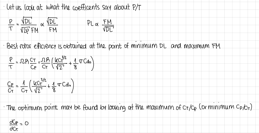
where is the best rotor efficiency obtained? (and formula)
at the point of minimum DL and maximum FM
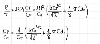
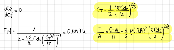
how can the optimum point be found? (and formula)
by looking at the maximum of c_T/c_P (or minimum c_P/c_T)

formulas when minimizing c_P/c_T
formulas
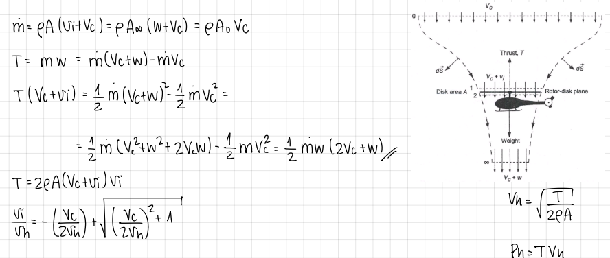
formulas for axial climb
formulas
(axial climb) as climb velocity increases, the induced velocity…
decreases
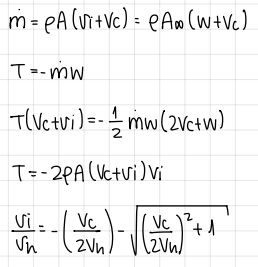
formulas for axial descent
formulas
axial descent: rotor flow states
normal → hover, climb, V_D « V_h → 0<V_c
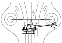
vortex ring state → intermediate state: -2V_h<V_c<0
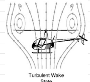
turbulent wake → intermediate state: -2V_h<V_c<0
windmill → V_c< -2V_h
intermediate states characteristics
a very complicated flow is observed
momentum theory is no longer valid
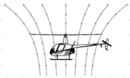
vortex ring state characteristics (setting for power)
the rotor pushes tip vortices down
oncoming air at the bottom pushes them up
vortices get trapped in a donut-shaped ring
the ring periodically grows and bursts
flow is highly unsteady
can only be empirically analized
turbulent state wake characteristics
rotor looks and behaves like a bluff body (or disk)
the vortices look like wakes behind the bluff body
the flow is unsteady, cannot be analyzed using momentum theory
need of empirical data
windmill brake state
flow is well behaved
no trapped vortices, no wake
momentum theory can be used
formula of axial flight induced velocity (MT)
formula

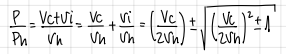
formula of axial flight power requirements (MT)
formula
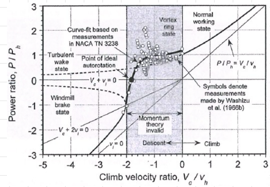
we observe a “zero power” point in the power curve. how is that possible? what is happening?
Zero power occurs at autorotation:
airflow through the rotor drives part of the blade, while drag on other parts absorbs the same amount.
The torques cancel, so net power is zero, even though the rotor still produces lift.
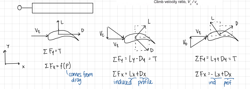
different diagrams and formulas depending on forward flight normal, upwards, downwards
formulas
autorotation mechanics:
the NET power consumption is zero
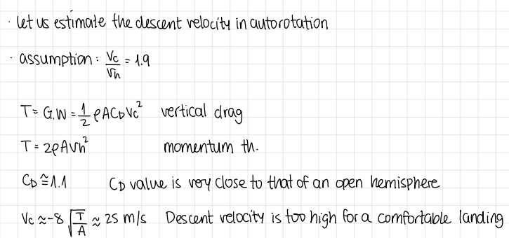
estimation of the descent velocity in autorotation: development
development
what do all helicopters must demonstrate for certification?
autorotation
what are all helicopters equipped with?
freewheeling hubs, to disconnect the rotor from the powertrain during autorotation
how is the vertical velocity in autorotation reduced?
by adding a horizontal velocity component, i.e. forward flight
what is MT good for?
to estimate rotor performance
what can’t be MT used for?
for rotor design
what doesn’t MT take into account?
number of blades
airfoil characteristics (lift, drag, angle, zero lift)
blade planform (taper, sweep, root-cut-out)
blade twist distribution
compressibility effects