Engineering Design & Material Selection
1/46
Earn XP
Description and Tags
Focus on the application of the content
Name | Mastery | Learn | Test | Matching | Spaced |
|---|
No study sessions yet.
47 Terms
Planning
Concept Development
System-Level Design
Detail Design
Testing & Refining
Production Ramp-Up
Product Development Process Phases
Identifying lead users
Identifying competitive products
Collecting user needs
Define product requirements
Develop alternative design concepts and evaluate to select one and build test concept prototypes
Concept Development invloves…
Defines what rather than how
Defined in early stage of product development process
Not latent
Solution-independent
Definition of requirement
Effectively communicate and define goals
Capture user expectations in binding contract
Ensure product fitness
Why the need for well-defined requirements?
Explicit (widely understood)
Unfulfilled (diff. to address)
Latent (currently unaddressed)
Types of user needs
Should weigh less than 4kg and must be protected against dust
Well formulated requirements
Generating a variety of concepts, Utilizing creativity and classification to fill gaps in the explored solution space (ex. Pugh Concept Screening Matrix)
Approach for concept generation phase
Using selection tool to justify a personal or team favorite and preferring solutions that are already implemented in existing products
Pitfalls of concept selection methods
Isometric 1:1:1, a and b=30°
Dimetric 1:1:1/2, a= 42° and b=7°
Trimetric free, 30°<a<45° and b<=30°
List the three axonometric projections
Orthogonal projections, Sections, Detail views
Main views in technical drawings include
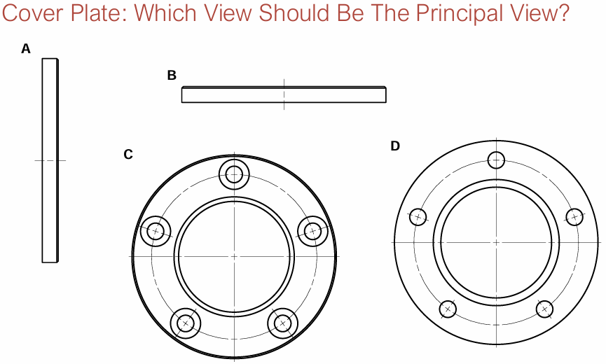
Choose principal view
Choose other required views and cuts
Draw views and cuts
Add dimensions
Verify
Technical drawing process
C
Top view below front view, object before projection plane
1st Angle
Top view above front view, object behind projection plane
3rd Angle
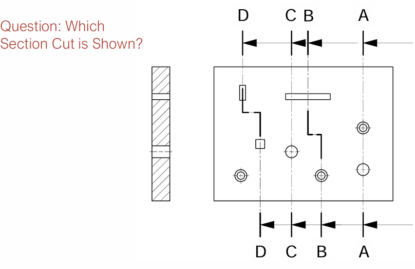
Full section
Half section
Local section
3 Types of Sections
C-C
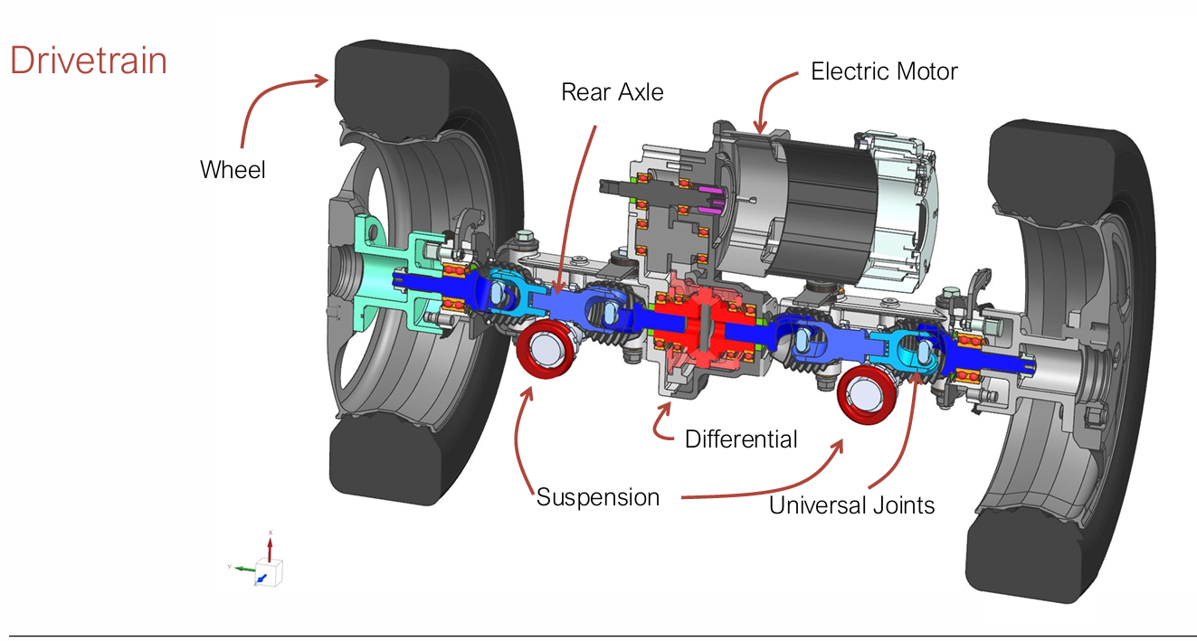
Antriebsstrang
Drivetrain
Federung
Suspension
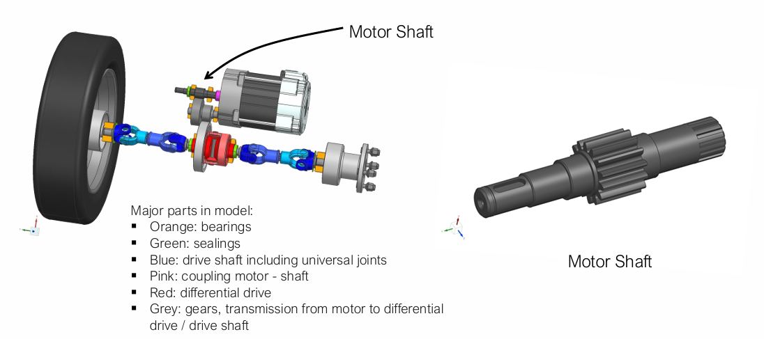
Motor Shaft
Intra-feature (Independent)
Inter-feature (Dependent)
Composite (two or more features)
Pattern (recurring relation features)
Feature types
Define rough geometry
Define geometric constraints
Evaluate Model (constraint solver)
Create variants by changing values and constraints
Parametric modeling guide aids to
Parts sharing some similarities
Part families definition
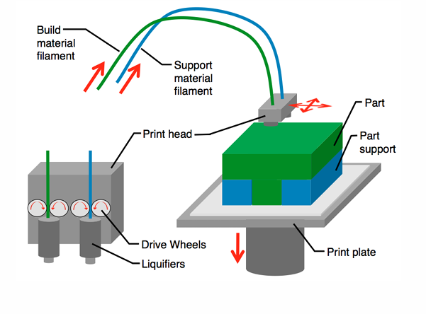
Fused Deposition Modeling
uPrint SE Plus, Stratasys
0.254 mm and 203 × 203 × 152 mm
Layer Height and maxiumum build envelope
STL file exportation in CAD
Cause of triangulation error
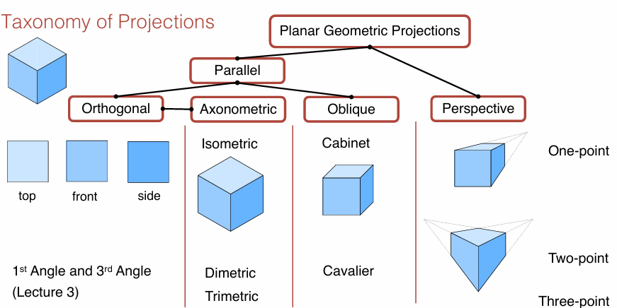
Taxonomy of Projections
While the dimensions can be measured in parallel projections the perspective projection is closer to the eye’s perception. Parallel projections are used in technical drawings, because all elements with equal length are equally dimensioned.
Difference Parallel vs Perspective Projection
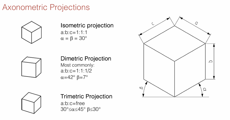
Axonometric Projections
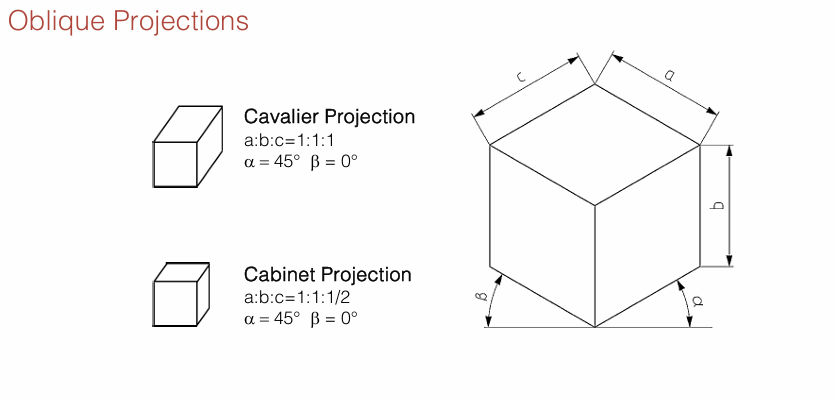
Oblique Projections
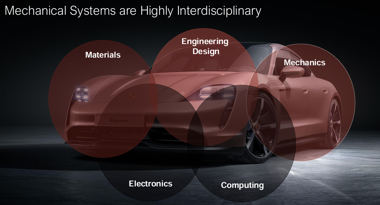
Mechanical Systems
Single person transport electric vehicle
Target of elderly or ppl w/o license
Max speed of 10,20,30 km/h
Range of 65 to 120 km
300 kg empty weight
160 kg payload
Infos to Kyburz PLUS II
3D wireframe models
3D surface models
3D solid models (B-reps, Solid Primitives)
Types of 3D models
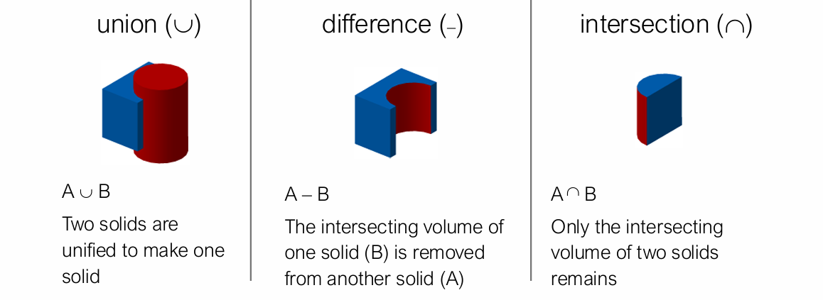
Boolean Set Operations
faces, edges and vertices
Boundary-representations consist of
Models can easily be changed and updated through the CAD interface or linked spreadsheets
Pros parametric modeling
a) Vertical, Horizontal, Perpendicular, Tangent, Perpendicular
b) Distance, Angle, Diameter, Radius
a)Basic Geometric Constraints vs. b) Dimensional Constraints
there is a sufficient amount of constraints and no degrees of freedom are left unconstrained
When a sketch is fully constrained…
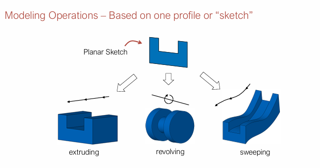
Recolving = non-intersecting sketch, Sweeping = profile is sweept along a defined curve
3 Modeling operations
B-rep
What is the main solid representation used in CAD sytems?
Continuity conditions ensure smooth transitions while avoiding visible discontinuities. This enhances both the aesthetic appeal and functional accuracy of the design.
Why is it important to use continuity conditions to connect curves and surfaces to represent freefrom objects ?
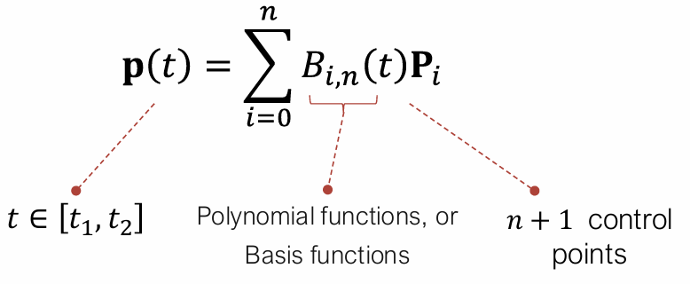
Bézier curves define a network of control points in approximated or interpolated form.
The Bézier curves degree is defined by the #control points minus 1.
If one point is moved the whole curve is affected.
Bézier curves
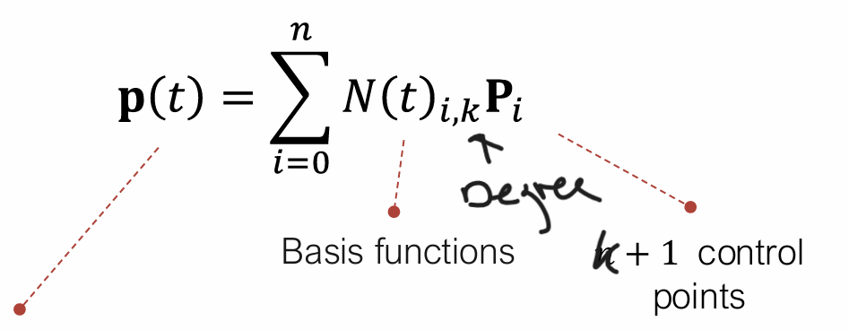
B-Splines are composite curves and a generalized form of Bézier curves
If the knot intervals are equal lenghts, the knot vector is uniform
The degree of each curve is k-1
Moving one point won’t affect the whole spline
B-spline
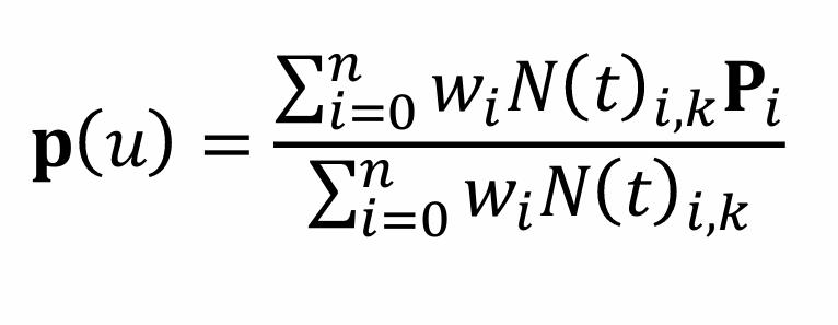
Non-uniform rational B-splines increase the generality of B-splines allowing almost any freeform curve/surface
Knot values can be non-uniformly spaced
Control points can be weighted
NURBS
Extruding an object from several profiles
Common applications in wing, hull and forged object design
Object created by interpolating a series of sections
Lofting
Bézier curves and surfaces
B-splines
NURBS
3D surface models include
A feature represents the engineering meaning of the geometry of a part or assembly
Definition feature
parametrize curves and surfaces using control points
The three 3D surface models can