Damage Control Coloring Book
1/121
There's no tags or description
Looks like no tags are added yet.
Name | Mastery | Learn | Test | Matching | Spaced |
|---|
No study sessions yet.
122 Terms
6.1 Duties and Responsibilities of Divisional Damage Control Petty Officer (DCPO)
Maintains DC duties as primary responsibilities
Conducts all PMS on portable DC equipment in divisional spaces
Supervises daily setting of specified material conditions within divisional spaces
6.1 Duties and Responsibilities of Division Officers (DIVO)
Assigns personnel to DC organizations on the Watch, Quarter, and Station Bill
Ensures divisional personnel are assigned requisite DC PQS (Personnel Qualification Standard)
Recommends a DCPO to the Department Head
Ensures Compartment Check-Off Lists (CCOLs) are current, accurate, and posted
Conducts spot checks of DC PMS (Preventative Maintenance System)
6.1 Duties and Responsibilities of Damage Control Assistant (DCA)
Submits all-hands DC training schedule to the Planning Board for Training (PB4T)
Informs the Damage Control Officer
(DCO) of changes to DC equipment
status
Oversees training and qualifications
of repair lockers and Damage Control
Central (DCC) personnel
Supervises training of all DCPOs
6.1 Duties and Responsibilities of Damage Control Officer (DCO)
Maintains hull, machinery, and electrical systems in battle readiness
Supervises firefighting and ensures Fire Bill adequacy
Organizes and trains Repair 5 in accordance with the Battle Bill
Acts as authorizing officer for use of installed ventilation for desmoking spaces after a fire is extinguished
6.1 Duties and Responsibilities of Department Heads
Ensures optimum readiness within the department
Ensures cooperative DC training with the DCA
Provides required personnel for repair lockers and inport fire parties
Ensures that personnel are qualified and assigned as Damage Control Petty Officers (DCPOs)
6.1 Duties and Responsibilities of Executive Officer (XO)
Keeps the CO advised as to the status of the ship’s readiness
Commands the Damage Control Training Team (DCTT)
DCTT is the shipboard train team responsible for training and self-assessing the crew’s response to damage control casualties.
Gives final approval for DCPOs
Heads PB4T
6.1 Duties and Responsibilities of Commanding Officer (CO)
Responsible for the safety of the ship and the lives of the crew
Ensures the command is adequately trained and continually exercised
Maintains a full awareness of the adequacy and operability of all DC equipment
Gives the order for Abandon Ship if necessary
6.2 Damage Control Repair Stations are located:
Repair 3 (AFT)
Repair 5 (ENG)
Repair 2 (FWD)
6.2 Rapid Response Team (RRT)
Proceeds directly to the scene of the casualty without full Fire Fighting Ensemble (FFE) or Self Contained Breathing Apparatus (SCBA) to provide initial limited attack casualty response
Designated U/W and I/P
RRT Includes:
Fire Marshal
Repair Electrician
Two advanced DC qualified personnel
6.2 Flying Squad/At-Sea Fire Party
Backs up the Rapid Response Team
First team to man a Repair Locker in full dress out
Combats a casualty U/W that requires minimal DC effort
Usually advanced DC qualified personnel who stand watch or stand roving watches
6.2 Repair Party Leader
In charge of the repair locker
Responsible for DC efforts in a designated area of the ship
Locker Officer is often assigned but is not required IAW the NTTP 3-20.31
6.2 Investigators
Roves in pairs, autonomously, in areas adjacent to affected compartments
Continuously reports new findings and update statuses to locker via hand held radio
Searching for panting or sweating bulkheads, structural damage, and any secondary/cascading damage caused by the casualty
Will use a 30 min SCBA; “on-air” at their own discretion
Ensures casualty boundaries remain set
6.2 On-Scene Leader (OSL)
Directs the DC team at the location of the casualty
Reports to the Repair Locker Leader
Determines the method of attacking the casualty
6.2 Attack Team Leader (ATL)
Reports to the OSL
Leads the attack team
Directs attack team efforts at the scene of the casualty
6.2 Attack Team
Nozzleman
Hoseman
Plugman
6.2 Duties and Responsibilities of (In-Port DC Organization) Command Duty Officer (CDO)
Reports directly to the CO
Responsible for the safety of the entire ship and its personnel
Typically second-tour division officer or senior
Assumes the duties of the CO when the CO is off the ship
6.2 Duties and Responsibilities of (In-Port DC Organization) Engineering Duty Officer (EDO)
In charge of the engineering plant
Coordinates DC efforts from Damage Control Center (DCC)
Functions as the DCA when the DCA is off the ship and casualties occur
6.2 Duties and Responsibilities of (In-Port DC Organization) Duty Fire Marshal
Assists the DCA with daily fire prevention, material conditions, and duty section training
Leads the ship’s Rapid Response Team
6.2 Duties and Responsibilities of (In-Port DC Organization) In-Port Emergency Team (IET)
The IET is a limited force which responds to a designated locker in case of a casualty in-port; normally called upon outside of normal working hours
The IET includes the RRT
6.2 Duties and Responsibilities of (Battle organization underway) Bridge Personnel
Officer of the Deck (OOD) is the CO’s primary assistant and their direct representative on the Bridge
Possess extensive knowledge of the ship’s systems and DC emergency procedures
Maneuver the ship to minimize the effects of wind, fire, and smoke
6.2 Duties and Responsibilities of (Battle organization underway) Damage Control Central (DCC)
General Quarters (GQ) station for the DCA
Receives and evaluates information from all repair parties
Keeps the Bridge informed
of DC progress
Initiates orders to repair
partiesMaintains all DC plots
Controls routes through
the ship to minimize
breaking of watertight
integrity
6.2 Duties and Responsibilities of (Battle organization underway) Main Control (MC)
GQ station for the Engineering Officer of the Watch (EOOW)
Controls and monitors Engineering Operational Casualty Control (EOCC) procedures
Responsible for starting and stopping installed systems
Responsible for propulsion
6.2 Duties and Responsibilities of (Battle organization underway) Central Control Station (CCS)
GQ station for the DCA and EOOW
One space that serves as MC and DCC on certain ship classes
6.2 Duties and Responsibilities of (Battle organization underway) Combat Information Center (CIC)
Led by the Tactical Action Officer (TAO), who maintains knowledge of engineering electrical plant status for warfare priority
Communicates with the DC organization as repairs are made and systems are brought back online
6.2 Duties and Responsibilities of (Battle organization underway) Combat Systems
Maintenance Center (CSMC)
The Combat Systems Officer of the Watch (CSOOW) coordinates all Combat Systems-related DC casualties from CSMC
Ensures that all damaged electronic equipment is repaired and brought back online
Serves the function of Repair 8 on ships with a robust combat suite
6.2 Duties and Responsibilities of (Battle organization underway) Helo Control Officer (HCO)
Communicates with pilot, coordinates landing with the Bridge, and oversees casualty control efforts
- On ship’s with an Air Operations
Department (LHA/LHD/LPD):
HCO is usually stood by a
departmental officer or CPO
- On ships just equipped for
helicopter operations
(LSD/CG/DDG/LCS): HCO is
usually stood by SUPPO
(Supply Officer) or ASUPPO
(Assistant Supply Officer)
6.2 Duties and Responsibilities of (Battle organization underway) Crash and Salvage Team
A.K.A. Crash and Smash Team
Trained in pilot rescue and to respond to flight deck emergencies
- Teams are comprised of Air Operations
Department personnel
- On ship’s without an Air Operations Department, all departments will provide personnel to ensure a fully manned Crash and Salvage Team
6.2 Duties and Responsibilities of (Battle organization underway) Medical
GQ station for the Senior Medical Officer (SMO) on big decks
GQ station for the Independent Duty Corpsman (IDC) on small decks
6.2 Duties and Responsibilities of (Battle organization underway) FWD & AFT Battle
Dressing Stations (BDS)
Administers first aid to personnel casualties in battle situations
Manned by medical department personnel and qualified stretcher bearers
Distributed throughout the ship to afford easy access (most ships have at least two)
Stocked and fully equipped to handle battle casualties
6.2 Duties and Responsibilities of (Battle organization underway) Rescue & Assistance Team (R&A)
Can be manned up In-port or U/W
Provides aid in the form of equipment and personnel for a different ship experiencing a casualty
Team will stage a specific list of DC equipment on or near the boat deck
6.3 Symbols (optional)
Fire: A, B, C, D
Smoke: S
Fire Protection System: FPS
Fire Fighting Water: FFW
Flooding: FL
Progressive Flooding: PFL
Structural Damage: STR
Hole: H (OVD, BHD, Deck)
Rupture: R (system)
Personnel Failure (injury): P, list name of person
Mechanical Failure: M, list equipment or system
Mechanical Damage: MD, list equipment or system
Weapons Hazard: WPN, list weapon type
Jammed Access: J, list hatch/scuttle number
Electrical Power Loss: E, list space
Toxic Gas: TOX
Chemical: CHM
Biological: BIO
Radiological: NUC
Fire Boundary: FB
Smoke Boundary: SB
Casualty Boundary: CB
6.3 Electronic Phone Circuits
J-Dial: Ship’s Service Telephone Circuit
Just like your home phone (keypad)
Shouldn’t be relied upon in emergency situations (fragile)
Requires power source (no redundancy)
IVCS: Integrated Voice Communication System
Operates on Ship’s Power
Can be used as for multi-station net or space to space comms
Up to 1 hour battery back-up
6.3 Sound Powered Phone Circuits
2JZ Damage Control and Stability: receiving reports and issuing orders to Repair Stations from DC Central
3JZ Main Deck Repair Circuit: coordinating DC efforts main deck and above
4JZ Forward Repair Circuit: DC Central to Repair 2
5JZ After Repair Circuit: DC Central to Repair 3
6JZ Amidships/Forward Repair Circuit: DC Central to Repair 4
7JZ After Propulsion Engineer Repair Circuit; DC Central/Main Control to Repair 5
8JZ Crash and Salvage Team: DCA to Flight Deck
6.3 General Announcing System
1MC General Announcing System:
Transmits general orders, information, and alarm signals to all areas in the ship
Includes Collision alarm, General alarm, Chemical Attack alarm, and Flight Crash alarm
Interior communication: Fast and direct means of comms between stations
4MC – Damage Control
21MC – CO’s Command
26MC – Machinery Control
6.4 Fire Triangle
Fuel
Heat
Oxygen
Triangle must be intact to create and sustain a fire
6.4 Fire Tetrahedron
Fuel
Heat
Oxygen
Chain Reaction
Product of the fire triangle’s uninhibited chemical chain reaction
Extinguishing agents disrupt the fire tetrahedron by eliminating one or more of the elements
6.4 Classes of Fire and their
Extinguishing Agents
Alpha: Water
Bravo: AFFF, PKP, HALON
Charlie: CO2
Delta: Jettison
Sierra: Water, AFFF, Jettison
6.4 Space Isolation
Mechanical and electrical isolation are performed at the discretion of the OSL
Electrical isolation is performed to de-energize equipment in casualty area prior to fire fighting efforts
Mechanical isolation is performed by operating valves and or fittings prior to space entry; reference: Main Space Fire Doctrine
6.4 Post Fire Actions
De-smoking is used to force an air change in the effected space
Ram Fan 2000 or Electric Box Fan may be used
Satisfactory post-atmospheric testing required before re-entry without an SCBA
Overhaul is performed by the attack team to ensure that the risk of smoldering materials don’t reflash
Naval Firefighter’s Thermal Imager (NFTI) and rakes are used to locate hot spots
6.5 Purple-K-Powder (PKP)
Class BRAVO fires
Extinguishes the fire by breaking up the combustion chain reaction
No cooling capability
Sizes: 18 / 27 pounds
Ranges: 19 / 21 feet
Discharge Times: 10 / 11 seconds
Compound will foul electronic components
6.5 Carbon Dioxide (CO2)
Class CHARLIE fires
Extinguishes the fire by displacing oxygen
Size: 15 pounds
Range: 4 to 6 feet
Discharge Time: ~35 seconds
Located within 30 ft of equipment with high potentials for a class “C” Fire
Keep grounded to deck to avoid shock from static electricity
6.5 Aqueous Film-Forming Foam (AFFF)
Class BRAVO fires
Extinguishes the fire by creating a vapor barrier and cooling
Size: 28 lbs (2.5 gal of premixed AFFF producing 16 gal of foam)
Range: 10 ft and decreasing
Discharge Time: 45 to 65 sec
6.5 Naval Firefighter’s
Thermal Imager (NFTI)
Used to locate the seat of a fire in smoke filled and dark spaces
Operated by the Attack Team Leader
2 modes of operation: PAN-while moving, CHOP-while fighting the fire
Can “wash out” in an environment that is too hot for too long
6.5 P-100 Portable Emergency Pump
Diesel engine driven centrifugal pump
Provides 100 gpm at 83 psi
20 ft suction lift; max 39 ft when used with a portable educator
Be mindful of exhaust if operating inside the ship
6.5 Electric Submersible Pump (ESP)
Centrifugal pump driven by a water-jacketed constant speed A/C electric motor
140 gpm at 70 ft, 180 gpm at 50 ft static head pressure
Cooled by pumped fluid and always used with a strainer
MUST wear proper electrical PPE in accordance with the NSTM 300: 450 VAC!
6.5 Perijet Eductor
Jet-type pump, no moving parts
Often used with an ESP or P-100 pump
Can be used with fluids with small particulate matter or that are more viscous
6.5 S-Type Eductor
Jet-type pump, no moving parts
Often used with an ESP or P-100 pump
Has a Foot Valve with a strainer to prevent flooding and clogging
6.5 Soft Patch
Used for systems of 150 psi or less
Gasket material must extend 2 in past damage
Not recommended for fuel or steam lines
6.5 Jubilee Patch
Used for systems with 100 psi or less
Gasket material must be large enough to overlap 2 in on all sides
6.5 Emergency Water-Activated
Repair Patch (EWARP)
Used for systems with 150 psi or less and does not exceed 300 degrees
Cannot be used on fuel or potable water systems (can contaminate the system)
2 Sizes: 3 in x 9 ft, 4 in x 15 ft
Fully hardened in 30 minutes
6.5 Various Patches
Box Patch: effective for holes with jagged edges
Hinged Plate Patch: designed for use over relatively small holes
Folding T-Patch: used for unevenly shaped holes
Hook Bolts: used to anchor a patch
6.6 Loop Configuration
Designed as a system of independent loops
Battle damage will not impact the entire firemain
Two types:
Horizontal
Vertical offset
6.6 Horizontal Loop Configuration
Two cross-connected mains on the damage control (DC) deck
Separated athwartships
6.6 Vertical Offset Loop Configuration
Components of the vertical offset loop
A starboard loop that is located on the first deck
A port loop that is located on the third deck, with cross-connects
Supplied by six fire pumps
6.6 Composite System Loop Configuration
Consists of more than one type of firemain system
6.6 Installed Eductor Activation
D: Open overboard DISCHARGE valve
F: Open FIREMAIN actuating valve
(Throttle valve to get eductor’s rated operating pressure)V: Ensure VACUUM is created by checking associated gage
DO NOT CONTINUE IF VACUUM IS NOT PRESENT
S: Open Drainage Main Cutout & Suction Valves
(Post a watch to monitor water level)
6.6 Dangers
Flooding the space
Ensure eductor is not misaligned
Make sure suction check valve is not degraded
Asphyxiation
Scuttle open
Ensure ventilation is operational
Secure eductor operation when water level is below suction line
6.6 (Installed Drainage Systems) Main
Provides emergency dewatering in engineering spaces
Reliable and has no moving parts
Uses galvanized pipe or copper-nickel tubing
Segregated by bulkhead stop valves
6.6 (Installed Drainage Systems) Secondary
Serves spaces at or below the waterline for spaces forward and aft of the main spaces
Independent of main drainage with its own eductors and sea connections
Piping is smaller in size than main drainage piping but can be cross connected
Example spaces served:
Steering gear rooms
Emergency diesel
generator roomsA/C machinery rooms
Chain lockers
List & trim control tanks
6.6 (Installed Drainage Systems) Special
Service spaces (heads, galleys, sickbays)
Magazines w/ sprinklers
Above waterline, near weather deck: drain through bulkhead check valve
Above waterline, NOT near weather decks: overboard discharge with deck drains
Below waterline: installed secondary eductors
6.6 (Installed Drainage Systems) Gravity
Consists of plumbing and deck drains
Installed most extensively in compartments above the waterline
Spaces above waterline are directed overboard
Spaces below waterline directed to tank or space where installed drainage can remove water
NOT designed to remove flooding water from ship as a result of damage
6.7 Buoyancy
An object floating or submerged in a fluid experiences an upward force equal to the weight of the fluid displaced by the object
6.7 Displacement
Weight of the volume of water that the ship displaces when floating freely
(in tons)
6.7 Draft
Depth of water a ship draws especially when loaded
Calculative: distance from the keel to the waterline (numbers on the bow and stern, 6" increments)
Mean: average of forward and aft drafts
Navigational: distance from the waterline to the lowest projections from the ship (i.e. sonar dome and screws)
6.7 Trim
Difference between the forward and aft drafts
6.7 Pitch
Up and down motion of the ship’s bow and stern as it moves through the sea
6.7 List
A definite attitude of transverse inclination of a semi-permanent nature
Inclination of a vessel to one side is normally due to weight distribution
6.7 Heel
A temporary inclination, generally involving motion. A ship normally
heels due to a sharp turn or a steady wind from the beam.
6.7 Sagging
Often due to seas or loading.
compression at the weather deck and tension at the keel, often due to seas or loading
6.7 Hogging
Often due to seas or loading.
Compression at the keel and tension at the weather deck, often due to seas or loading
6.7 Define Center of Buoyancy (COB) and how it moves
The center of the underwater hull volume when viewed in transverse direction
It’s the point at which all buoyant forces can be considered to be acting in a vertical direction
COB stays in the center of underwater hull volume
When the ship rolls starboard, the center of buoyancy (B) moves starboard
COB follows the waterline
As displacement increases from a weight addition, the ship sinks down, waterline goes up, and COB goes up
More underwater hull volume
6.7 Define Center of Gravity (COG) and how it moves
The point at which all weights could be concentrated
COG moves towards a weight addition
COG moves away from a weight removal
Gravity (G) follows the weight shift
If weight is shifted up, Buoyancy (B) and Meatcenter (M) do not change
6.7 Gravity Metacenter (GM)
Distance (GM) between the center of gravity (COG) and the metacenter is a prime determiner for stability:
Large GM: fast roll period
Small GM: Slow roll period
6.7 Stability always reduced when
Gravity is high
Gravity is off centerline
6.7 Free Surface Effect
Occurs when a compartment or tank is only partially flooded / filled.
As the ship rocks, water tends to maintain a level condition causing sloshing of water
As water shifts in direction of heel, center of gravity shifts decreasing the righting arm and reducing the stability
This effect is reduced by pocketing, swash plates, and baffles
Breadth is the biggest factor in the free surface effect, not the depth
6.7 Free Communication Effect
Three conditions for Free Communication Effect:
Compartment must be open to the sea
Compartment must be partially flooded
Compartment must be off centerline
The continuous addition and removal of water causes a horizontal shift of COG
Equates to a virtual rise of COG
6.7 Benefit of Compartmentalization
Isolates the Casualty
Reduce Free Surface & Free Communication Effect
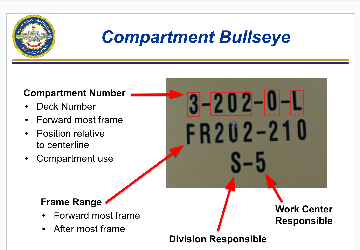
6.7 Compartment Bullseye
6.7 Classification of Fittings
X-RAY / YOKE / ZEBRA: Special permission required, must be logged in the DC Closure Log if opened during the corresponding Condition of Readiness
CIRCLE X-RAY / CIRCLE YOKE / CIRCLE ZEBRA: May be opened with out special permission to transit, inspect, and access vital spaces
Dog ZEBRA: Set for Darken ship
WILLIAM: Vital sea suctions,
ventilation, and maintenance
fittings for mobility
CIRCLE WILLIAM: Access and
ventilation fittings
6.7 Material Conditions of Readiness
Provides increasing degrees of protection
against the spread of damage
X-RAY: In homeport, in fair weather, normal working hours
YOKE: At sea / inport during peacetime, outside of normal working hours
MODIFIED YOKE: fittings below the waterline are closed, above the waterline may be left open to improve accessibility and habitability
ZEBRA: Set during General Quarters, entering and leaving during wartime, when in danger
MODIFIED ZEBRA: CO may wish to set a modified material condition ZEBRA to provide higher survivability stance than condition YOKE but less restrictive than ZEBRA
CIRCLE WILLIAM: Set to prevent contamination in a CBR environment
6.7 Compartment Check-Off
Lists (CCOL)
Located at every entry to a compartment
Required for every compartment or weather deck where DC facilities are located
Provide an itemized list and location of all DC fittings and the personnel responsible for the setting of material conditions of readiness
Master/Duplicate/Partial CCOLs maintained
6.8 Installed CO2 system
Used on Class A, B, and C fires, found in auxiliary spaces and lockers.
CO2 Fixed-Flooding systems: installed in spaces that require protection of flammables
Paint lockers
Paint mix and issue rooms
Flammable liquid storerooms
Flammable compressed-gas cylinder storerooms
GTM / GTG Modules (DDG/CG’s)
Identified by red bottles with no stripes
System Actuation:
Activated either manually or pneumatically
Break glass on pull-box cover
Grasp handle and pull
Pull cable out three to five inches
System Operation:
Activated at the local pull station or pull box
Activation of the system causes release of all CO2 into a discharge manifold
The entire protected space is flooded with CO2 gas
CO2 hose reel system: is used in electrical and machinery spaces where the potential for a class C fire is high
Two 50 lb CO2 cylinders
50 ft of hose on a reel
Valve assembly
Horn assembly
6.8 Halon 1301 System
Used against “B” fires in:
Main machinery and engine rooms
Auxiliary machinery and boiler rooms
Ship service or emergency generator rooms
Main propulsion or generator engine modules
Recovery, Assist, Secure, and Traverse (RAST) machinery rooms
Tactical Towed Array Sonar (TACTAS) handling rooms
Flammable liquids storage and issue rooms
CO2 actuators are installed inside and outside the space
Actuates local and remote audible and visual alarms
Ventilation automatically shuts down
Time delays:
60 sec (manned)
30 sec (unmanned)
Completely discharges in 10 sec
6.8 HALON 1301 System Safety Precautions
Personnel are not allowed in a space where Halon has been discharged without an SCBA (Self- Contained Breathing Apparatus)
Gas Free engineering procedures must be conducted for reentering spaces after being flooded with Halon 1301
Lethal byproducts of Halon:
Hydrogen Cyanide
Hydrogen Fluoride
Hydrogen Bromide
6.8 AFFF Stations
Designed to protect compartments or areas where flammable/combustible liquid fires are likely to occur:
Machinery spaces, fueled vehicle stowage spaces, helicopter hangars
Stations provide a solution of 6% AFFF concentrate and 94% seawater at a flow rate of 60 to 1,000 GPM to installed AFFF Systems
6.8 AFFF Piping System
Supplies AFFF bilge sprinklers, hose reels, and hangers
Can be cross connected so the forward station can provide to the aft station and visa versa
6.8 Installed AFFF Systems
Locations where overhead AFFF sprinkler systems are installed
Hangers
Tank decks
Well decks
Vehicle cargo holds
Weapon elevator pits
Fuel pump rooms
Safety concerns
Hydrogen Sulfide (H2S) exposure
Hearing protection at AFFF station
6.8 AFFF Bilge Sprinkler System
Installed throughout the machinery spaces
Used to create a vapor barrier if flammable liquid spills in the bilges
6.9 Battle Dress
Battle dress requirements:
Flame resistant variant (FRV) coveralls
All buttons buttoned
Pant cuffs tucked into boots or socks
Life preserver worn on the waist (or kept at General Quarters station)
Flash hood and gloves
Remove metal from uniform
Empty pockets
6.9 Fire Fighter’s Ensemble (FFE)
Provides optimal protection from exposure to heat, cold, steam, water, and sharp objects
Consists of an outer shell, a vapor barrier, and an inner fire-retardant thermal liner
Helmet
Protects the head, neck, and face from short-duration flame exposure, heat, and falling objects
Made of heat-resistant fiberglass
Gloves
Protect against abrasions, flash exposure, and heat
Flash Hood
Provides protection to the head, neck, and face, except for the eyes
Made of a Kevlar and rayon knit with an elastic face closure
Available in a single size that fits all
Boots
Have steel safety toes and puncture-proof
steel insolesAuthorized for repair party electricians to wear
when performing their duties
6.9 Self-Contained Breathing Apparatus (SCBA)
Delivers air through a second stage regulator and face shield
Can be refilled in a smoke-filled environment
Available in two different sizes of bottles (30 or 45 minutes) with an external pressure indicator: both bottles charged to 4,500 PSI
Exertion and physical limitations of user impact available time of bottle
6.9 Emergency Escape
Breathing Device (EEBD)
10 Minutes of O2, smoke protection only
Never used to combat a fire! Wearing the hood is optional, bottom bag is pressure relief
Activated when pulled out of the box. Single use, disposable unit
Can create unbreathable air, contaminated with Lithium Hydroxide if damaged
Check pressure gage, ensure needle points to GREEN, not RED
The total shipboard quantity for EEBDs as found in NSTM 077
Ship’s Complement 150%
Embarked Personnel 100%
Berthing Spaces 100%
(one EEBD per rack)Engineering Spaces 200%
6.10 Electric Box Fan
115V A/C Electric fan
Moves 3200 cubic feet of air /min
Used with smoke curtains to create smoke control zones using installed ventilation or CPS
6.10 RAM Fan 2,000
Water turbine actuated by Fireman or P-100 Pump which operates Fan Blades
Moves 2000 cubic feet of air/min
Must be grounded to prevent static electricity build up
Used with “elephant trunks” to direct contaminated air
6.11 Toxic
A space where poisonous substances are present, exposure cannot exceed OSHA (Occupational Safety and Health Administration) standards
6.11 Permissible Exposure Limit (PEL)
The maximum permissible concentration of a toxic or harmful physical agent to which personnel may be exposed
6.11 Lower Explosive Limit (LEL)
The minimum percent by volume of a gas that, when mixed with air, will form a flammable mixture
6.11 Upper Explosive Limit (UEL)
Upper end of the explosive range. Concentrations above this limit are too rich to explode or burn. Concentrations below the UEL are within the explosive range.
6.11 Immediately Dangerous to Life and Health (IDLH)
Any atmosphere that meets any of the following conditions:
- flammable vapors 10% or greater of the LEL;
- an oxygen content of less than 19.5% or greater than 22%;
- the presence of toxicants above a level that would not allow personnel to escape within 30 minutes without impairment or irreversible health effects.
Oxygen surplus: oxygen level above 22%
Increased danger of explosion
Oxygen deficiency: oxygen level below 19.5%
19.5%: normal
17%: deep, fast breathing
15%: dizziness and buzzing in the ears
9%: unconsciousness
7%: can cause death
6.11 Fire Watch Requirements
All affected sides must be watched
Communication devices must be available
Portable fire extinguisher or hose must be within reach
PPE (Personal protective equipment) must be worn
Goggles or safety glasses (as required)
Helmet (as required)
Hearing protection (as required)
NAVOSH (Navy Occupational Safety and Health) approved respirator (as required)
“30, 40, 50” Rule
Watch must stay until 30 minutes after work or until cool to touch
No hot work can be performed within 40 feet of painting or chemical cleaning
Flammables must be moved 50 feet from work area