PMS(1) - Protection and Safety Monitoring
1/11
Earn XP
Description and Tags
For now, this set will encompass PMSR&PMSS
Name | Mastery | Learn | Test | Matching | Spaced | Call with Kai |
|---|
No analytics yet
Send a link to your students to track their progress
12 Terms
Overall
Simplified Diagram
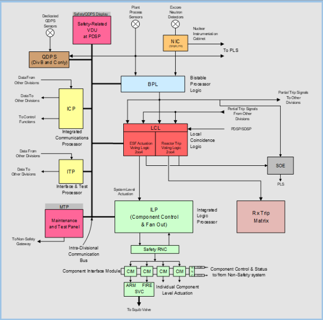
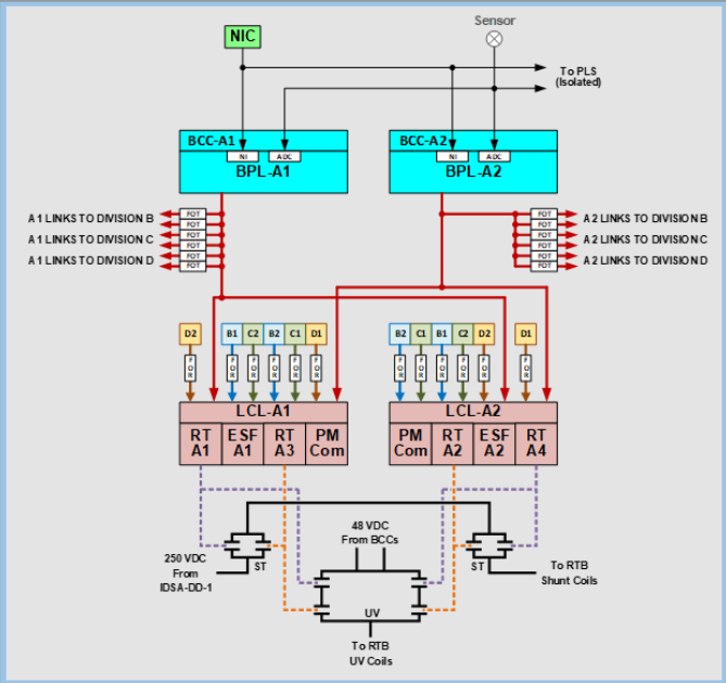
BCC
Simplified Diagram
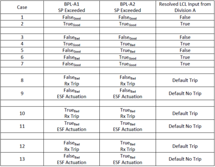
Logic Table
True/False
Good/Bad
RTS/ESF
Key Points
Default:
RTS: Trip
ESF: Do NOT Actuate
Reactor Trip Breakers
Location
Access
12422(23) Near Main Control Room
Doors locked, key in WCC/MCR
Color scheme is different than traditional commercial breakers, use “OFF” button to trip open
Conditions to RESET “S”
P-3 ON
AND
“S” signal has been active ≥60sec
Hardware Implemented Reactor Trip Signals from Manual Switches
“Hardwired”
“CARS”
C - CMT Actuation
A - ADS 1-3 Actuation
R - Reactor Trip Switch
S - Safeguards “S”
*These switches also generate P-4, EXCEPT Manual Reactor Trip Switch
**The RSR Manual Reactor Trip Switch is software so therefore WILL generate a P-4 demand
Critical Safety Function Visual Alerts
Actuated by:
Safeguards “S”
Manual Reactor Trip
P-4
Can be reset after P-3 ON
PMS
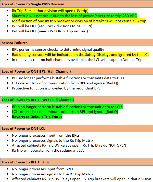
Loss of Power Consequences
Design Definitions
Single Failure Criterion
Redundancy
Independence
Physical Separation
Single Failure Criterion
Single failure will not prevent needed protection or cause unnecessary one
Redundancy
No. of divisions available > No. of required for test/maint.
Independence
Electronically isolated
Physical Separation
Separate rooms (Fire Protection)
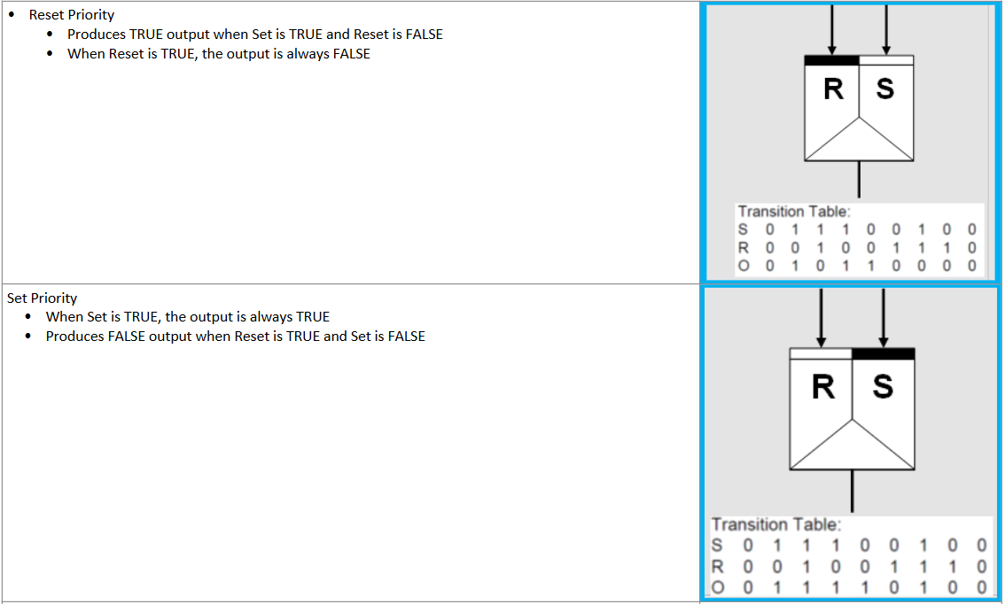
Set/Reset Latches
Black Line indicates which signal has priority
Safeguards “S”
Latched vs. Unlatched
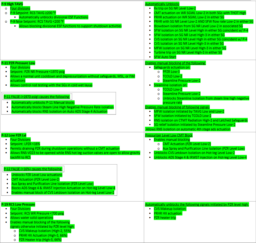
Setpoints/Interlocks
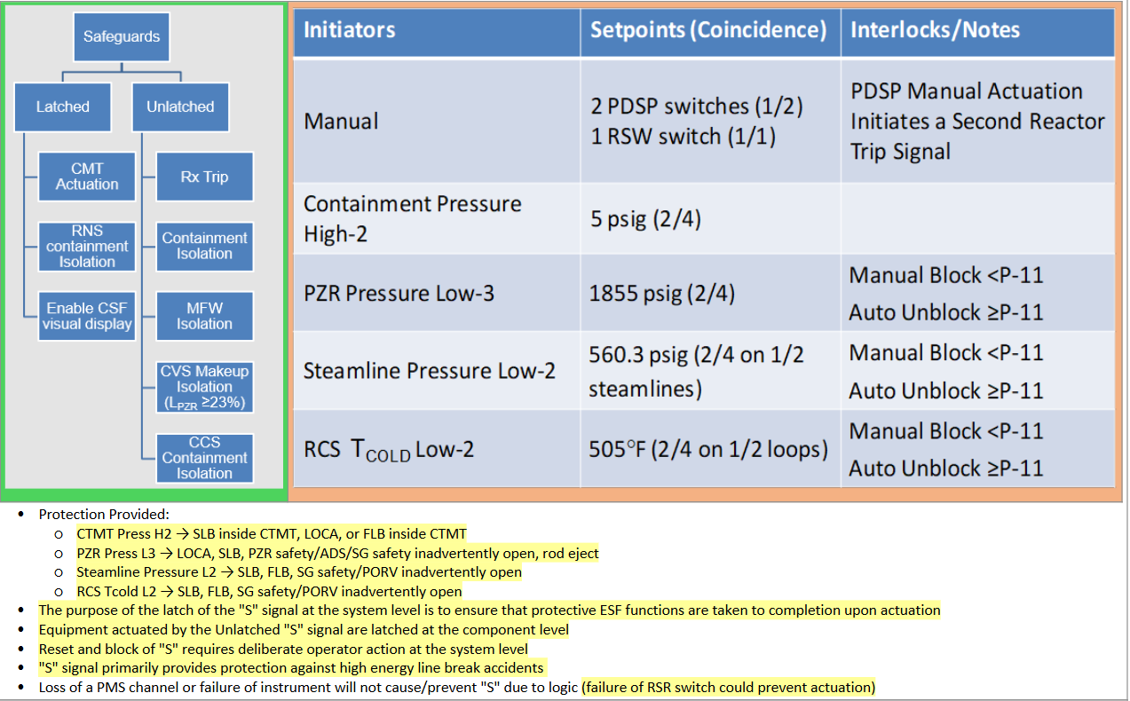
Safeguards “S”
Permissive Overview