EE1Y Digital
0.0(0)
Card Sorting
1/101
Earn XP
Description and Tags
Last updated 9:51 AM on 4/23/23
Name | Mastery | Learn | Test | Matching | Spaced | Call with Kai |
|---|
No analytics yet
Send a link to your students to track their progress
102 Terms
1
New cards
microcontroller
extremely compact self contained microcomputers that can only run one task at a time
2
New cards
microcontroller types
8-bit, 16-bit, 32-bit
3
New cards
microcontroller componenets
* clock
* CPU
* instruction decoder
* input/output ports
* memory
* CPU
* instruction decoder
* input/output ports
* memory
4
New cards
clock
keeps everything synchronised
5
New cards
CPU
heart of the microcontroller
6
New cards
instruction decoder
controls the chip and caries out each instruction
7
New cards
data bus
bidirectional between ROM, RAM, I/O, instruction decoder and CPU that carries the read/write memory
8
New cards
address bus
unidirectional from CPU to ROM, RAM or I/O that carries the address
9
New cards
ALU
data manipulation
10
New cards
registers
temporary storage of data to be manipulated
11
New cards
complex instruction set computer
* complete all encompassing instruction set
* many microprocessors
* simple instructions are single clock cycle
* more complex ones are several cycles
* many microprocessors
* simple instructions are single clock cycle
* more complex ones are several cycles
12
New cards
reduced instruction set computer
* reduced instruction set of simple commands
* many microcontrollers
* most commands operate in fewer clock cycles
* many microcontrollers
* most commands operate in fewer clock cycles
13
New cards
machine language
fundamental basic instructions
14
New cards
assembly language
machine specific instructions
15
New cards
n-bits wide
eg in a 32-bit ARM each number is 32-bit ie 4 bytes wide
16
New cards
bus wires
eg in a 32-bit MCU there are 32 parallel wires
17
New cards
von Neumann architechture
all memory is held together
18
New cards
Harvard architechture
ROM and RAM are held separately
19
New cards
how many memory addresses can a 32-bit system access?
2^32 = 4GB
20
New cards
how many bits can each memory address hold on a 32-bit system?
32-bits
21
New cards
logic 1
2\.3V - 3.3V (or 5.0V)
22
New cards
logic 0
0\.0V - 1.0V
23
New cards
undefined logic level
1\.0V - 2.3V
24
New cards
why does a blue LED require more voltage than a red LED?
blue light is higher energy than red
25
New cards
LED terminals
anode and cathode
26
New cards
LED forward current
current flowing from anode to cathode
27
New cards
connecting an LED to light when logic 1
connect between Vdd and Vss
28
New cards
limit red LED connected to 3.3V MCU to 5mA
* V from MCU is 3.3V
* V drop across diode is 2.2V
* V remaining is 3.3 - 2.2 = 1.1V
* V=IR
* 1.1 = 0.005 x R
* 1.1/0.005 = 22 ohms
* V drop across diode is 2.2V
* V remaining is 3.3 - 2.2 = 1.1V
* V=IR
* 1.1 = 0.005 x R
* 1.1/0.005 = 22 ohms
29
New cards
DAC output values
* Vo = (D/2^n)Vr
* Vo = analogue output voltage
* D = value of binary input word
* n = number of bits in input word
* Vr = value of the voltage reference
* Vo = analogue output voltage
* D = value of binary input word
* n = number of bits in input word
* Vr = value of the voltage reference
30
New cards
DAC output step size
Vr/2^n
31
New cards
DAC maximum output value
D = (2^n) - 1
32
New cards
kelvin divider
* string of resistors creates a ladder of voltages
* one of these is switched to output
* one of these is switched to output
33
New cards
weighted resistor DAC
network of different resistances each switched by the digital bits
34
New cards
weighted resistor DAC disadvantages
* very wide range of resistor values is needed for a large number of bits
* resistors must be high precision
* needs low resistance switches if the lowest R is small
* leads to errors for large number of bits
* resistors must be high precision
* needs low resistance switches if the lowest R is small
* leads to errors for large number of bits
35
New cards
offset
lowest value (0V assumed)
36
New cards
Vref
* when least significant bit is highest value
* eg when 8-bit digital code is 1111 1111
* eg when 8-bit digital code is 1111 1111
37
New cards
range
largest value minus the smallest one
38
New cards
resolution
* smallest analogue change
* analogue different between consecutive numbers
* Vref/2^n or range/(2^n)-1 for an n-bit DAC
* analogue different between consecutive numbers
* Vref/2^n or range/(2^n)-1 for an n-bit DAC
39
New cards
ADC - DAC system
* changing signal is samples at a regular time interval
* put the digital values through DAC to get the analogue output for the speakers
* sampling has caused a blockiness that needs smoothing
* low pass filter eliminates all sharp edges
* put the digital values through DAC to get the analogue output for the speakers
* sampling has caused a blockiness that needs smoothing
* low pass filter eliminates all sharp edges
40
New cards
pull down resistor
resistor goes between ground and the connection between the switch and MCU
41
New cards
pull up resistor
resistor goes between Vdd and the connection between switch and MCU
42
New cards
ADC output
* D = (Vi/Vr)2^n
* D = digital output value
* Vi = analogue input voltage
* Vr = reference voltage
* n = number of bits in converter output
* D = digital output value
* Vi = analogue input voltage
* Vr = reference voltage
* n = number of bits in converter output
43
New cards
quantisation error
the error from converting an infinitely graded signal to a digital one with finite steps
44
New cards
ideal greatest quantisation error
one half of the step width or half of one least significant bit equivalent on the voltage scale
45
New cards
how to reduce quantisation error
* step width can be narrowed by increasing the number of bits in the ADC process
* however increases complexity, cost and time
* however increases complexity, cost and time
46
New cards
sampling frequency
when performing an ADC a sample is taken of the analogue signal and quantised to the accuracy defined by the resolution of the ADC, generally done at the sampling frequency
47
New cards
Nyquist frequency
the sampling frequency must be at least double that of the highest frequency component of the signal
48
New cards
sample and hold
since a conversion take a finite time the input must stay steady during this time
49
New cards
V1 > Vref
Vout = Vdd
50
New cards
V1 < Vref
Vout = Vss
51
New cards
flash
* resistor chain provides a ladder of reference voltages
* one comparator on each rung of the ladder
* some logic to turn the outputs into binary
* very fast
* for n-bits requires (2^n)-1
* one comparator on each rung of the ladder
* some logic to turn the outputs into binary
* very fast
* for n-bits requires (2^n)-1
52
New cards
successive approximation
* make successive guesses
* use a DAC from your guessed digital code
* use a comparator to tell you if guess is too high or low
* adjust accordingly
* for n-bits requires n guesses
* use a DAC from your guessed digital code
* use a comparator to tell you if guess is too high or low
* adjust accordingly
* for n-bits requires n guesses
53
New cards
crosstalk
* where many channels are sent through one ADC there may be an influence of one on the others
* common problem on cheap multichannel digitisers
* common problem on cheap multichannel digitisers
54
New cards
pulse width modulation
simple method of using rectangular digital waveform to control an analogue variable
55
New cards
duty cycle
pulse on time (t_on)/pulse period (T)
56
New cards
PWM waveform average
* Vref \* duty cycle/100
* eg 3.3V\*0.2 = 0.66V
* eg 3.3V\*0.2 = 0.66V
57
New cards
how to extract an average value from a PWM signal
use a low pass filter
58
New cards
period to use for a lightbulb
100Hz
59
New cards
period to use for a motor
10x - 100x the revs per second
60
New cards
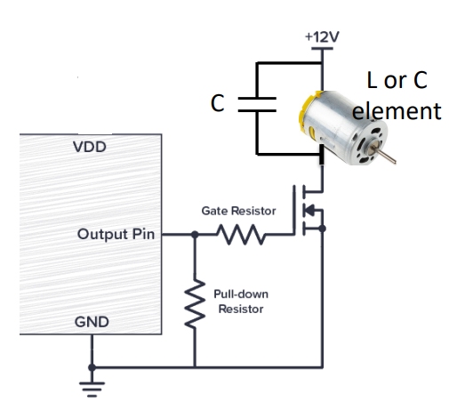
transistor usages
* need to drive an element with a high voltage
* need to drive an inductive or capacitive element
* need to drive an inductive or capacitive element
61
New cards
gate resistor for transistor
to limit the current that comes out of the MCU and it typically a few hundred ohms
62
New cards
transistor with a capacitor
63
New cards
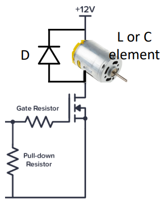
transistor with a diode
64
New cards
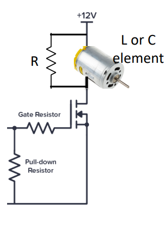
transistor with a resistor
65
New cards
timer
some circuit to measure time and so initiate an even when a certain time has elapsed
66
New cards
interrupt
a method that allows a program to be suspended so that the CPU can deal with a certain occurrence and once this has been dealt with the original program can continue to execute as required
67
New cards
tasks
distinct activities that are performed each of which has a block of code that is executed
68
New cards
software polling
the computer is in charge and checks for action when it sees fit
69
New cards
interrupt driven
the hardware is in charge and tells the program that something needs to be done
70
New cards
polling disadvantages
* central processor cannot perform any other tasks during a polling routine
* all inputs are treated equally so a response to an urgent event may be delayed until a relatively insignificant number of potential inputs are screened
* all inputs are treated equally so a response to an urgent event may be delayed until a relatively insignificant number of potential inputs are screened
71
New cards
stack
* place in RAM
* holds a copy of the program counter (where program left off)
* holds copies of the CPU registers
* stack pointer set to where all this stuff went so it can be retrieved later
* holds a copy of the program counter (where program left off)
* holds copies of the CPU registers
* stack pointer set to where all this stuff went so it can be retrieved later
72
New cards
interruption vector
points to the location of the interrupted service routine
73
New cards
fixed interruption vector
have highest priority for when things go wrong with the MCU
74
New cards
interrupt mechanisms
* interrupts can be prioritised
* interrupts can be masked (switched off if not needed)
* interrupts can be nested
* interrupts can be masked (switched off if not needed)
* interrupts can be nested
75
New cards
why can interrupts be bad for data?
extended state of system may be changed by ISR code so have to ensure code it written such that all data and resources will be uncorrupted on return
76
New cards
interrupt service routine good practice
* should not change or interfere with too much memory
* will respond to a new input but only needs to set a flag telling the main program that a new input is waiting
* should execute as fast as possible so make it short
* will respond to a new input but only needs to set a flag telling the main program that a new input is waiting
* should execute as fast as possible so make it short
77
New cards
when should interrupts be used?
for infrequent events (1000s of clock cycles), if more infrequent polling should be used
78
New cards
simple timer
* digital counter consisting of a string of flip flops will count up in binary
* can load a start number to initialise the flip flops
* can read the binary output
* can just wait until it has counted all the way to its max
* can load a start number to initialise the flip flops
* can read the binary output
* can just wait until it has counted all the way to its max
79
New cards
what does clock speed give us?
time resolution
80
New cards
number of bit in flip-flop gives us?
maximum interval
81
New cards
timer polling
* program can set a timer and continuously check if it has reached a given value
* when it has it can run scheduled code
* when it has it can run scheduled code
82
New cards
timeout polling
* program can set a timer and when it has elapsed it will run our code
* timeout does not need polling
* can do things in the meantime
* timeout does not need polling
* can do things in the meantime
83
New cards
system tick timer
* used by the ticker function
* used to call a repeated interrupt
* ensure sampling the ADC at regular intervals
* be careful not to call faster than the time it takes to run the code
* used to call a repeated interrupt
* ensure sampling the ADC at regular intervals
* be careful not to call faster than the time it takes to run the code
84
New cards
task scheduling
* if you use a timer the code must execute faster than the interval between the timer events
* best not to have polling in these since it may overrun its time
* best not to have polling in these since it may overrun its time
85
New cards
synchronous serial communication
transmit a clock signal alongside the data with one clock pulse for each bit of data
86
New cards
master
initiates transmission
87
New cards
slave
receives/transmits when told
88
New cards
serial link SPI
* assume the shift registers in master and slave are 8-bit
* each register is loaded with a new word via parallel I/O lines
* master then produces 8 clock pulses
* for each clock pulse data is output from the MSB of each register (serial data out)
* each SDO is connected to the LSB of the other shift register (serial data in)
* as each bit is clocked out of one register it is clocked into the other
* after 8 clock cycles the word that was in the master shift register has been transferred to the slave shift register and vice versa
89
New cards
serial peripheral interface (SPI)
* bus operates with the master/slave configuration
* is a synchronous serial data communication protocol
* is reasonably fast
* no address, control or acknowledgements sent
* is a synchronous serial data communication protocol
* is reasonably fast
* no address, control or acknowledgements sent
90
New cards
how does a master device start an SPI transfer
* configures the SPI clock (SCLK) to be a frequency that the recipient slave device can handle
* sets the chip select line (CS) of the intended recipient to 0V
* starts the clock pulses on SCLK to indicate that that data is to be transferred
* simultaneously sends data as consecutive bits on MOSI
* number of bits in each data frame can be configured but is usually between 4 and 16 bits
* slave returns data in the same manner on MISO
91
New cards
where is SPI used?
* applications with data streaming
* chips and modules that usually sit on the same PCB or are at least in the same instrument
* short distances where the clock and data lines are well controlled
* many peripheral chips have this ‘legacy’ standard interface as it is simple
* chips and modules that usually sit on the same PCB or are at least in the same instrument
* short distances where the clock and data lines are well controlled
* many peripheral chips have this ‘legacy’ standard interface as it is simple
92
New cards
SPI advantages
* full duplex communication
* higher throughput
* complete protocol flexibility for the bits transferred
* not limited to 8-bit words
* slaves don’t need unique addresses
* higher throughput
* complete protocol flexibility for the bits transferred
* not limited to 8-bit words
* slaves don’t need unique addresses
93
New cards
SPI disadvantages
* no in-band addressing
* no hardware flow control
* no hardware slave acknowledgement
* supports only one master device
* only handles short distances
* no hardware flow control
* no hardware slave acknowledgement
* supports only one master device
* only handles short distances
94
New cards
SPI simple link
* SPI protocol with just 3 wires
* serial clock
* master data output/slave data input
* master data input/slave data output
* only for a single slave
* not all slaves accept the SS being low all the time, some require a high low transition to start them off
* serial clock
* master data output/slave data input
* master data input/slave data output
* only for a single slave
* not all slaves accept the SS being low all the time, some require a high low transition to start them off
95
New cards
SPI with chip select
* SPI protocol with 4 signal wires
* master data output/slave data input
* master data input/slave data output
* slave chip select (usually active low)
* when multiple slave devices exist the master must output a unique chip select signal for each slave
* for n slaves we need (3+n) cables
* master data output/slave data input
* master data input/slave data output
* slave chip select (usually active low)
* when multiple slave devices exist the master must output a unique chip select signal for each slave
* for n slaves we need (3+n) cables
96
New cards
clock polarity (CPOL)
* CPOL = 0 is actively high
* it is normally low when no transmission
* when active it goes high for each bit
* CPOL =1 is actively low
* it is normally high when no transmission
* when active is goes low for each bit
* it is normally low when no transmission
* when active it goes high for each bit
* CPOL =1 is actively low
* it is normally high when no transmission
* when active is goes low for each bit
97
New cards
inter-integrated circuit bus (I2C)
* uses only 2 wires
* data can only be transmitted in one direction at a time (half duplex)
* data can only be transmitted in one direction at a time (half duplex)
98
New cards
I2C protocol
* each peripheral is known as a node and can act as either a master of a slave
* master controls the data transfer and generates the clock signal
* slave is any device addressed by the master
* more than one microcontroller can be connected to the bus and they can claim the master role at different times
* all data is transferred in block of 8-bits (1 byte)
* each byte is followed by a 1 bit acknowledgement from the receiver
99
New cards
I2C start condition
defined by a high-to-low transition of SDA when SCL is high
100
New cards
I2C stop condition
defined by a low-to-high transition of SDA while SCL is high