Unit 23 pipe-welding symbols
1/50
There's no tags or description
Looks like no tags are added yet.
Name | Mastery | Learn | Test | Matching | Spaced |
|---|
No study sessions yet.
51 Terms
____ dimensions are applied to the centerlines of the pipe and fittings to serve as reference points for locating items in the layout.
Location
A ____ pipe layout may specify several methods of connecting the pipe and fittings.
double-line
Dimensions are usually expressed in ____ when they measure more than one foot.
feet and inches
Double-line drawings may include use of the ____ welding symbols to indicate the kinds of welds required for assembling the components of the pipe layout.
standard
For joints that are socket welded, the ends are ____.
squared
Reference to special charts for symbol interpretation are necessary when fabricating pipe layouts that use ____ symbols.
company
Simple fittings, such as elbows and tees, are ____ represented.
pictorially
Single-line drawings are generally used to show pipe layouts for nominal pipe sizes of less than ____ inches.
12
Special symbols have been developed to indicate the methods to be used for connecting the components of a pipe ____.
Assembly
When pipe and fittings are to be butt welded, the ends are ____.
beveled
A pipe layout can be represented by any number of _____ views, by an oblique view, or by an isometric view.
orthographic
A __ pipe layout may specify several methods of connecting the pipe and fittings.
Double-Line
Dimensioning for pipe layout components is accomplished by the addition of ___ and notes to the drawings.
specifications
Double-line drawings are used for pipe layouts that use large sizes of pipe and fittings __inches and over.
12
Pipe __ are drawings use special sets of symbols to identify the components of piping systems, including pipe, valves, fittings, flanges, and equipment.
A number of companies have developed their own sets of symbols, both for single-line and double-line drawings.
true
In the case of complex layouts in double-line drawings, the pipe size must be more than 12".
false
Pipe layouts are shown through the use of single-line and double-line drawings.
true
Single-line drawings are always used to show pipe layouts for nominal pipe sizes of less than 12". This is a standard practice for all companies.
false
The runs of pipe on a pipe layout are shown without any indication of pipe sizes.
true
Brushing

Cross reducing
Cross straight size

Elbow 45 Degree

Elbow 90 Degree

elbow turned down

Elbow turned up

Joint connecting pipe

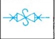
Joint expansion

Reducer concentric

Reducer Eccentric

Sleeve

Tee straight size

tee outlet up

tee outlet down

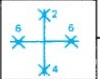
tee reducing

union

angle valve check

angle valve gate (elevation)

angle valve gate (plan)

Angle valve globe (elevation)

Angle valve globe (plan)

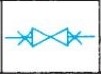
Check Valve straight way

cock

float valve

gate valve
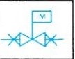
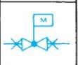
Gate valve motor operated
globe valve
globe valve motor operated
quick opening valve
safety valve