mot Cont final
0.0(0)
0.0(0)
Card Sorting
1/146
There's no tags or description
Looks like no tags are added yet.
Study Analytics
Name | Mastery | Learn | Test | Matching | Spaced | Call with Kai |
|---|
No study sessions yet.
147 Terms
1
New cards

____ 1. This is a step down transformer:
T
2
New cards

____ 2. The primary side of this transformer is wired in series.
F
3
New cards

____ 3. The primary side of this transformer is wired in parallel.
T
4
New cards
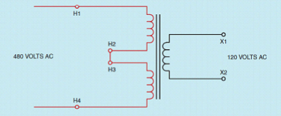
____ 4. This is a step up transformer.
F
5
New cards
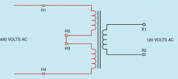
____ 5. This is a step down transformer.
T
6
New cards
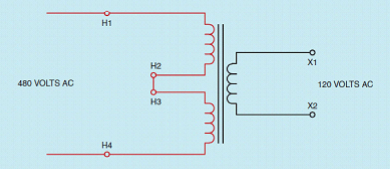
____ 6. The primary side of this tranformer is wired in series.
T
7
New cards
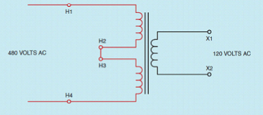
____ 7. The primary side of this tranformer is wired in parallel.
F
8
New cards

____ 8. This is a step up transformer:
F
9
New cards
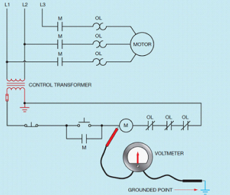
____ 9. This is considered a floating ground system.
F
10
New cards
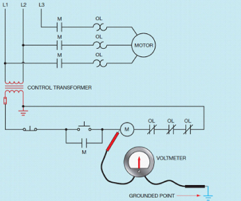
____ 10. This is considered a grounded system.
T
11
New cards
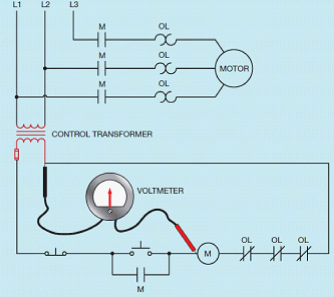
____ 11. This is considered a floating ground system.
T
12
New cards
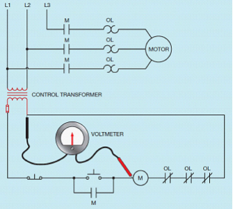
____ 12. This is considered a grounded system.
F
13
New cards
____ 13. Variable voltage control is used with small fractional horsepower motors that operate light loads, such as fans and blowers
T
14
New cards
____ 14. An autotransformer is the most efficient and reliable method of supplying variable AC voltage.
T
15
New cards
____ 15. Many small single phase motors change speed by varying the amount of voltage applied to the motor.
T
16
New cards
____ 16. It is not possible to change the AC voltage on a motor.
F
17
New cards
____ 17. DC voltage applied to an inductive device causes little harm.
F
18
New cards
____ 18. The main advantage of an eddy current clutch is that there is no mechanical connection between the rotor and drum
T
19
New cards
____ 19. If the motor speed decreases, the output voltage of the electrotachometer increses.
F
20
New cards
____ 20. The armature poser supply is used to provide variable DC voltage to the armature of the motor.
T
21
New cards
____ 21. The armature of a large DC motor has a very low resistance.
T
22
New cards
____ 22. If a load is removed, motor speed decreases.
F
23
New cards
____ 23. Alternators are often used to control the speed of several induction motors that require the same change in speed, such as motors on a conveyer line.
T
24
New cards
____ 24. The IGBT is a voltage-controlled device, not a current-controlled device.
T
25
New cards
____ 25. The output voltage of an alternator is controlled by the amount of DC excitation current.
T
26
New cards
____ 26. The standard frequency used in the United States and Canada is 50 Hz.
F
27
New cards
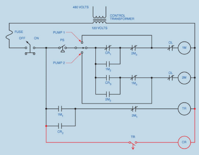
____ 27. The pressure switch shown below as: a. Normally Open c. Normally Open Held Closed b. Normally Closed d. Normally Closed Held Open
D
28
New cards
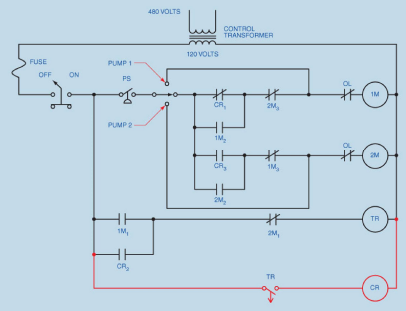
____ 28. When the pressure switch below closes, which starter will energize first? a. 1M b. 2M
A
29
New cards
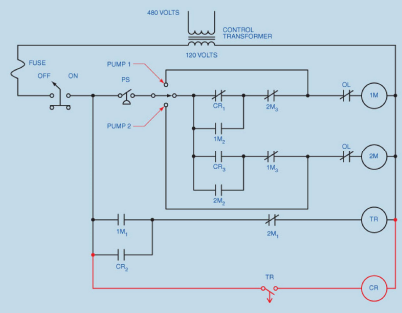
____ 29. Is the timer TR shown below an on-delay timer or an off-delay timer? a. On-Delay b. Off-Delay
B
30
New cards
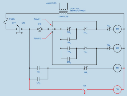
____ 30. In the event one pump should fail, the____________ permits the pressure switch to control the other pump only. a. Pressure Switch c. Rotary Switch b. Off-Delay Timer d. None of these
C
31
New cards
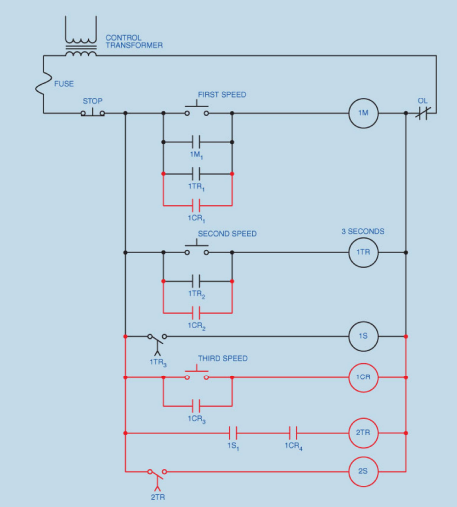
____ 31. Is the timer 1TR shown below an on-delay timer or an off-delay timer? a. On-Delay b. Off-Delay
A
32
New cards
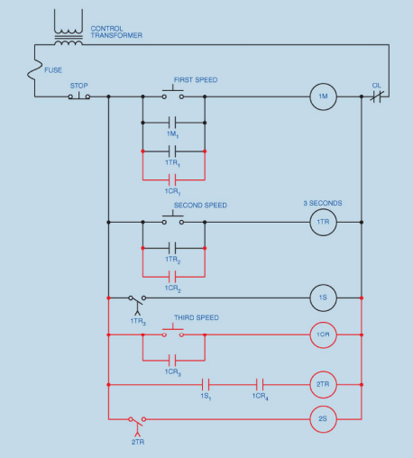
____ 32. Assume that the THIRD SPEED push button is pressed and the motor starts in its first or lowest speed. After a delay of 3 seconds the motor accelerates to its second speed, but never accelerates to its highest or third speed. Which of the following could cause this problem? a. CR coil is open c. Coil 1TR is open b. Coil 2TR is open d. Coil 1S is open
B
33
New cards
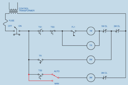
____ 33. Temperature switch TS1 is shown as: a. Normally Open c. Normally Open Held Closed b. Normally Closed d. Normally Closed Held Open
D
34
New cards
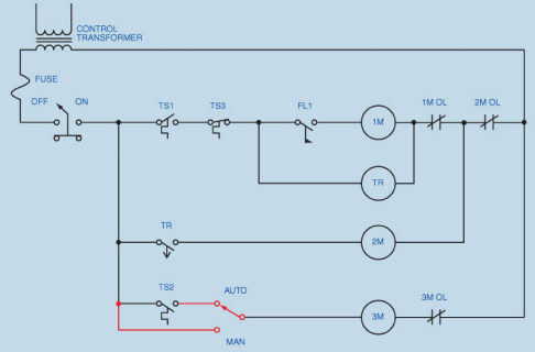
____ 34. Temperature switch TS2 is shown as: a. Normally Open c. Normally Open Held Closed b. Normally Closed d. Normally Closed Held Open
A
35
New cards
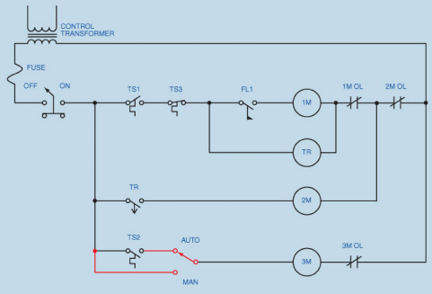
____ 35. Is the timer TR shown below an on-delay timer or an off-delay timer? a. On-Delay b. Off-Delay
B
36
New cards
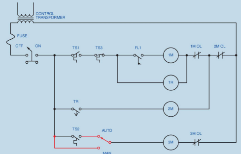
____ 36. Temperature switch TS3 is shown as: a. Normally Open c. Normally Open Held Closed b. Normally Closed d. Normally Closed Held Open
B
37
New cards
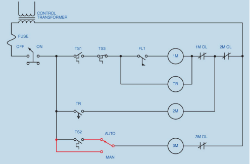
____ 37. Assume that contact TS1 closes and the air injection blower motor starts operating, but the high pressure pump motor does not start. What could cause this problem? a. Temperature switch TS3 is open. c. Flow switch FL1 is defective and did not close. b. Coil 2M is opern. d. Coil TR is open
C
38
New cards
____ 38. Which of the following is not a main electrical test instrument used in troubleshooting? a. Ammeter c. Voltmeter b. Ohmmeter d. Fluxmeter
D
39
New cards
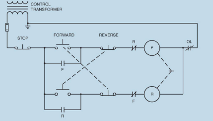
____ 39. Use the circuit shown below. The motor will not start in either forward or reverse direction when the START push buttons are pressed. Which of the following could not cause the problem?
a. F coil is open.
c. The control transformer fuse is blown.
b. The overload contact is open.
d. The stop push button is not making a complete circuit.
a. F coil is open.
c. The control transformer fuse is blown.
b. The overload contact is open.
d. The stop push button is not making a complete circuit.
A
40
New cards
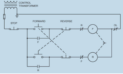
____ 40. Use the circuit shown below. Assume that the motor is running in the forward direction. When the REVERSE push button is pressed, the motor continues to run in the forward direction. Which of the following could cause the problem?
a. The normally open side of the reverse push button is not making a complete circuit when pressed.
c. The normally closed side of the reverse push button is not breaking the circuit when the reverse push button is pressed.
b. R contactor coil is open.
d. There is nothing wrong with the circuit. The stop push button must be pressed before the motor will stop running in the forward direction and permit the motor to be reversed.
C
41
New cards
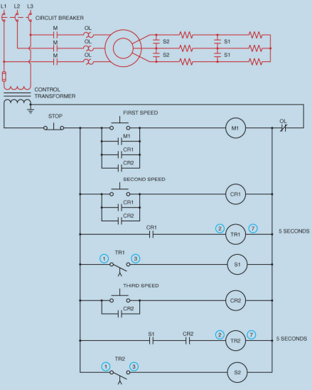
____ 41. When the THIRD SPEED push button is pressed, the motor starts in first speed but never accelerates to second or third speed. Which of the following could not cause this problem? a. Control relay CR1 is defective. c. Timer TR1 is defective. b. Control relay CR2 is defective. d. Contactor coil S1 is open.
B
42
New cards
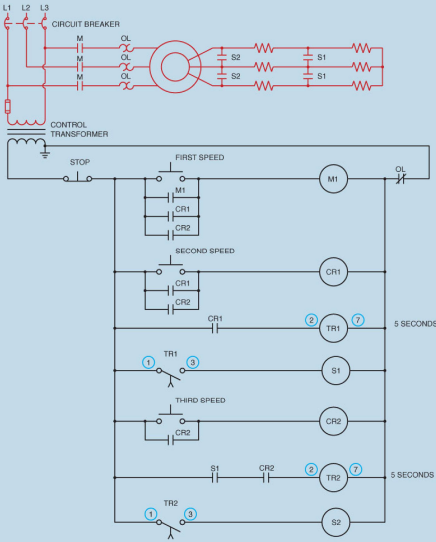
____ 42. When the THIRD SPEED push button is pressed. The motor starts in second speed, skipping first speed. After 5 seconds, the motor accelerates to third speed. Which of the following could cause the problem? a. S1 contactor coil is open. c. TR1 timer coil is open. b. CR1 contactor coil is open. d. S1 load contacts are shorted.
D
43
New cards
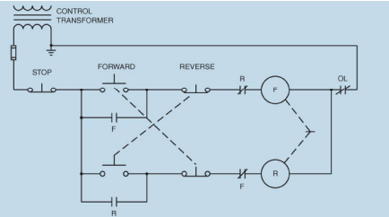
____ 43. Use the circuit shown below. If a voltmeter is connected across the normally open FORWARD push button, the meter should indicate a voltage value of: a. 0 volts c. 60 volts b. 30 volts d. 120 volts
D
44
New cards
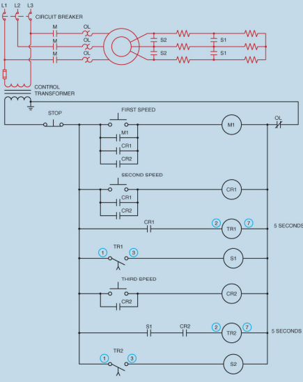
____ 44. Assume that the fused jumper is connected across terminals 1 and 3 of TR2 timer. What would happen if the jumper were left in place and the FIRST SPEED push button pressed?
a. The motor would start in its lowest speed and progress to second speed, but never increse to third speed.
c. The motor would not start.
b. The motor would start operating immediately in third speed.
d. The motor would start in second speed and then increase to third speed.
a. The motor would start in its lowest speed and progress to second speed, but never increse to third speed.
c. The motor would not start.
b. The motor would start operating immediately in third speed.
d. The motor would start in second speed and then increase to third speed.
B
45
New cards
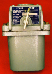
____ 45. This manual starter is in a a. waterproof enclosure c. explosion-proof enclosure b. dust-proof enclosure d. none of these
C
46
New cards
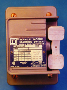
____ 46. This manual starter is in a a. waterproof enclosure c. explosion-proof enclosure b. dust-proof enclosure d. none of these
A
47
New cards
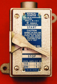
____ 47. This manual starter is in a a. waterproof enclosure c. explosion-proof enclosure b. dust-proof enclosure d. none of these
B
48
New cards
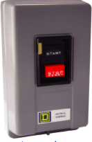
____ 48. This is a a. Automatic start c. Disconnect b. relay box d. Manual starter with low voltage release
D
49
New cards
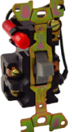
____ 49. This is a a. single phase motor starter c. three phase motor starter b. two phase motor starter d. emergency stop
A
50
New cards
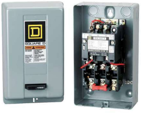
____ 50. This is a a. single phase motor starter c. three phase motor starter b. two phase motor starter d. emergency stop
C
51
New cards

____ 51. This symbol is for a a. magnetic circuit breaker c. disconnect switch b. transformer d. 3-phase motor
C
52
New cards
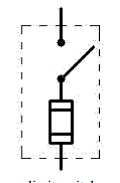
____ 52. This symbol is for a a. limit switch c. overload relay b. circuit breaker d. fuse disconnect switch
D
53
New cards
A

54
New cards

____ 54. This symbol represents a a. fuse c. motor starter b. transformer d. alarm
C
55
New cards

____ 55. This symbol is a a. fuse c. circuit breaker b. disconnect switch d. contactor
C
56
New cards
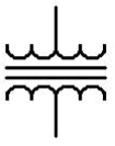
____ 56. This symbol is a a. air transformer c. auto transformer b. iron core transformer d. decepticon
B
57
New cards

____ 57. This is a a. relay c. contactor b. solinoid d. fuse
D
58
New cards

____ 58. These symbos are a. pressure switches c. temperature switches b. float switches d. limit switches
B
59
New cards

____ 59. These symbols are a. temperature switches c. pressure switches b. delay switches d. flow switches
C
60
New cards

____ 60. These symbols are a. temperature switches c. float switches b. pressure switches d. flow switches
A
61
New cards

____ 61. These symbols are a. float switches c. temperature switches b. pressure switches d. flow switches
D
62
New cards

____ 62. This symbol is a a. fuse c. disconnect b. overload relay d. breaker
B
63
New cards

____ 63. This symbol is a a. single phase induction motor c. two phase induction motor b. three phase induction motor d. none of these
B
64
New cards

____ 64. This symbol is a a. single phase induction motor c. two phase induction motor b. three phase induction motor d. none of these
A
65
New cards
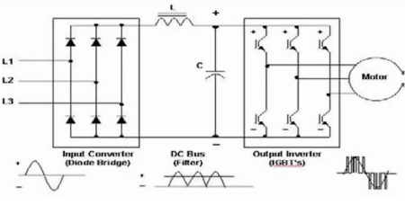
____ 65. The is a basic schematic of a a. inverter c. variable frequency drive b. rectifier d. motor starter
C
66
New cards

____ 66. This is a _____________ contact. a. Normally Closed On-Delay c. Normally Closed OFF-Delay b. Normally Open On-Delay d. Normally Open OFF-Delay
B
67
New cards

____ 67. This is a _____________ contact. a. Normally Closed On-Delay c. Normally Closed OFF-Delay b. Normally Open On-Delay d. Normally Open OFF-Delay
A
68
New cards

____ 68. This is a _____________ contact. a. Normally Closed On-Delay c. Normally Closed OFF-Delay b. Normally Open On-Delay d. Normally Open OFF-Delay
D
69
New cards

____ 69. This is a _____________ contact. a. Normally Closed On-Delay c. Normally Closed OFF-Delay b. Normally Open On-Delay d. Normally Open OFF-Delay
C
70
New cards
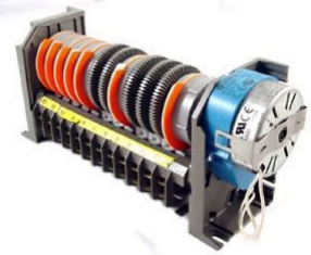
____ 70. This is a ____________. a. Pneumatic Timer c. CAM Timer b. 11 Pin Timer d. Electronic Timer
C
71
New cards
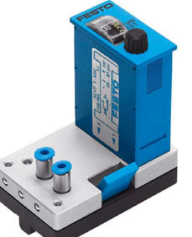
____ 71. This is a ____________. a. Pneumatic Timer c. CAM Timer b. 11 Pin Timer d. Electronic Timer
A
72
New cards
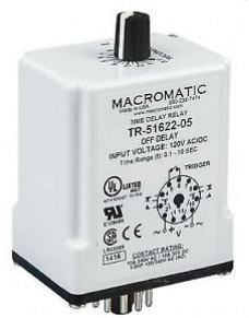
____ 72. This is a ____________. a. Pneumatic Timer c. CAM Timer b. 11 Pin Timer d. Electronic Timer
B
73
New cards
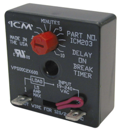
____ 73. This is a ____________. a. Pneumatic Timer c. CAM Timer b. 11 Pin Timer d. Electronic Timer
D
74
New cards
____ 74. Start the motor with short jabs of power at full voltage. a. Across the line start c. Jogging b. Capacitor start d. Inching
C
75
New cards
____ 75. Start the motor with short jabs of power at reduced voltage. a. Across the line start c. Jogging b. Capacitor start d. Inching
D
76
New cards
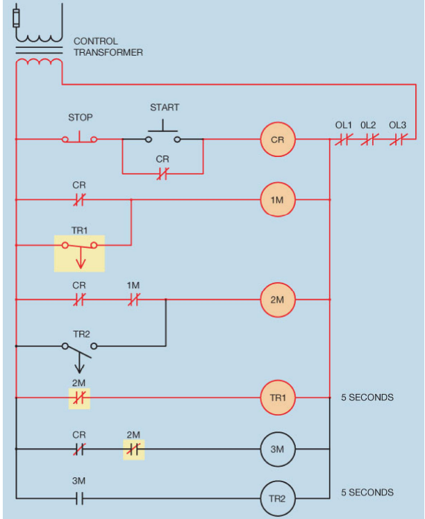
____ 76. Based on the figure below, which motor or set of motors are currently running? a. Motor 1 only c. Motor 1 and Motor 2 b. Motor 2 only d. Motor 3 only
C
77
New cards
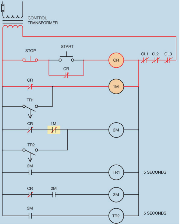
____ 77. Based on the figure below, which motor or set of motors are currently running? a. Motor 1 only c. Motor 2 and Motor 3 b. Motor 2 only d. Motor 3 only
A
78
New cards
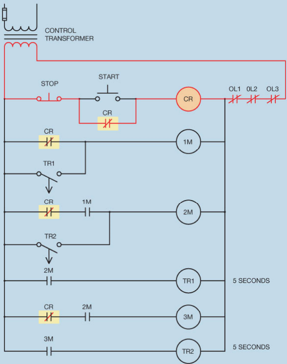
____ 78. Based on the figure below, which motor or set of motors are currently running? a. Motor 1 only c. Motor 3 only b. Motor 2 only d. None of the motors are running
D
79
New cards
____ 79. What is the synchronous speed of a three-phase motor that contains six poles per phase and connected to 60Hz? a. 10 RPM c. 360 RPM b. 1200 RPM d. 60 RPM
B
80
New cards
____ 80. What is the synchronous speed of a three-phase motor that contains three poles per phase and connected to 60Hz? a. 7200 RPM c. 2400 RPM b. 180 RPM d. 20 RPM
C
81
New cards
____ 81. What is the synchronous speed of a three-phase motor that contains 4 poles per phase and connected to 60Hz? a. 7200 RPM c. 2400 RPM b. 240 RPM d. 1800 RPM
D
82
New cards
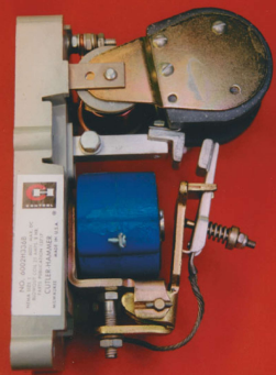
____ 82. This is a ____________. a. AC Motor Starter c. Three-Phase Starter b. DC Motor Starter d. Single-Phase Starter
B
83
New cards
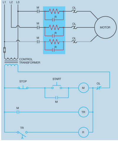
____ 83. The figure below is an example of ___________. a. Autotransformer Starting c. Reactor Starting b. Step Starting d. Resistor Starting
D
84
New cards
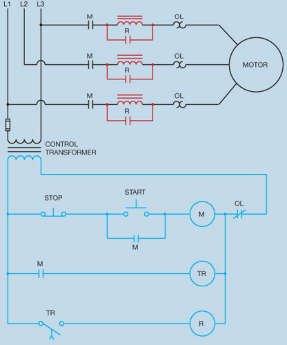
____ 84. The figure below is an example of ___________. a. Autotransformer Starting c. Reactor Starting b. Step Starting d. Resistor Starting
C
85
New cards
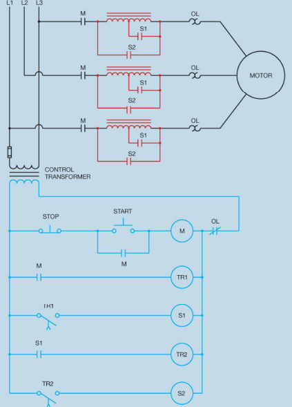
____ 85. The figure below is an example of ___________. a. Autotransformer Starting c. Reactor Starting b. Step Starting d. Resistor Starting
B
86
New cards
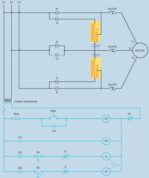
____ 86. The figure below is an example of ___________. a. Autotransformer Starting c. Reactor Starting b. Step Starting d. Resistor Starting
A
87
New cards
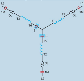
____ 87. The stator windings in the figure below are shown to be connected in ________. a. Series c. Delta b. Shunt d. Wye
D
88
New cards
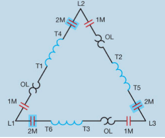
____ 88. The stator windings in the figure below are shown to be connected in ________. a. Series c. Delta b. Shunt d. Wye
C
89
New cards
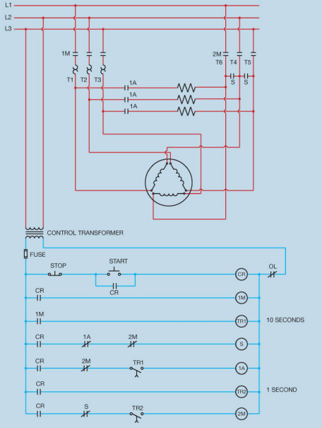
____ 89. The figure below represents a ___________. a. wye-delta starter c. delta starter b. delta-wye starter d. wye starter
A
90
New cards
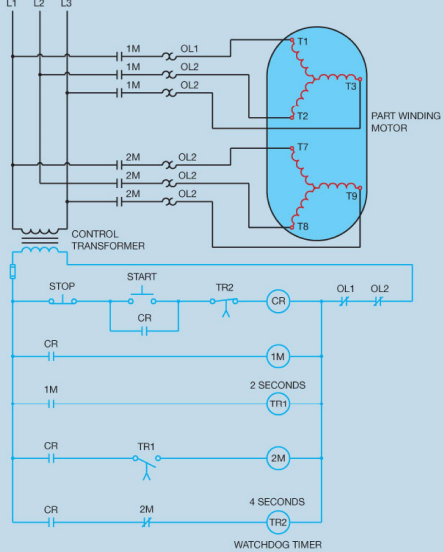
____ 90. Refer to the figure below. When the START button is pressed, the motor does not start. Which of the following could not cause this problem? a. The control transformer fuse is blown. c. TR1 timer coil is open. b. Overload contact #2 is open. d. Control relay coil CR is open
C
91
New cards
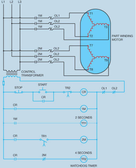
____ 91. Refer to the figure below. When the START button is pressed, the motor does not start. After a 4-second time delay control relay CR de-energizes. Which of the following could cause this problem? a. TR1 timer coil is open. c. CR coil is open. b. 1M starter coil is open. d. 2M starter coil is open.
B
92
New cards
____ 92. The nameplate of a part winding motor indictes a full load current rating of 72 amperes. What current rating should be used when sizing the overload heaters? a. 72 amperes c. 144 amperes b. 36 amperes d. none of these
B
93
New cards
____ 93. The nameplate of a part winding motor indictes a full load current rating of 50 amperes. What current rating should be used when sizing the overload heaters? a. 25 amperes c. 50 amperes b. 100 amperes d. none of these
A
94
New cards
___ 94. The speed of the rotating magnetic field in a single phase motor is call the _________. a. Synchronous speed c. Split speed b. Asynchrouous speed d. Relay speed
A
95
New cards
____ 95. Calculate the frequency of an 8% slip. a. 16.8 Hz c. 0.08 Hz b. 4.8 Hz d. 8 Hz
B
96
New cards
____ 96. Calculate the frequency of an 4% slip. a. 1.2 Hz c. 4.8 Hz b. 4 Hz d. 2.4 Hz
D
97
New cards
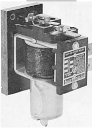
____ 97. This is a ______________. a. Out-of-Step relay c. Field contactor used in the starting of a synchronous motor b. Polarized field frequency relay d. Rotor of a synchronous motor
A
98
New cards
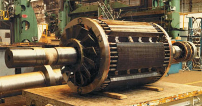
____ 98. This is a ______________. a. Out-of-Step relay c. Field contactor used in the starting of a synchronous motor b. Polarized field frequency relay d. Rotor of a synchronous motor
D
99
New cards
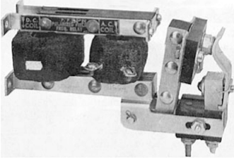
____ 99. This is a ______________. a. Out-of-Step relay c. Field contactor used in the starting of a synchronous motor b. Polarized field frequency relay d. Rotor of a synchronous motor
B
100
New cards
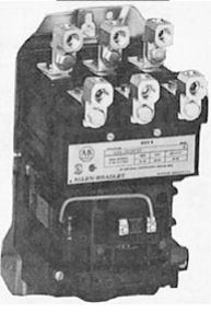
____ 100. This is a ______________. a. Out-of-Step relay c. Field contactor used in the starting of a synchronous motor b. Polarized field frequency relay d. Rotor of a synchronous motor
C