05 Power Electronics
1/25
There's no tags or description
Looks like no tags are added yet.
Name | Mastery | Learn | Test | Matching | Spaced | Call with Kai |
|---|
No analytics yet
Send a link to your students to track their progress
26 Terms
Which fields are part of power electronics?
Solid State Physics
Control Theory
Systems
Circuit Theory
Simulation
Modules
What are some examples of power electronics?
DC/DC Converters (300 W, 2 phases, conversion of 48 V DC to 12 V DC, for voltage supply)
Inverters (2 MW, 6 phases, creation of multiple sinusoidal voltages, supple of multi-phase machines)
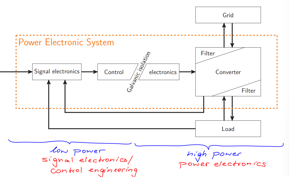
How is a Power Electronics Circuit structured?
Composed of a low and a high power system
Isolated from one another by a Galvanic Isolation (no conductors inbetween)
Low Power System: Singal electronics + control
High Power System: Electronics + Converter and Filters
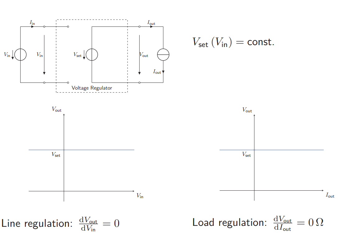
What kind of Voltage Regulators are there and what is their goal?
They aim to keep voltage constant
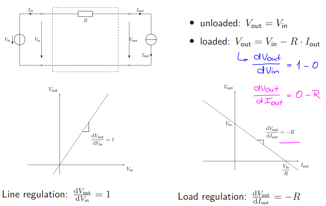
Voltage Regulator with Series Resistance
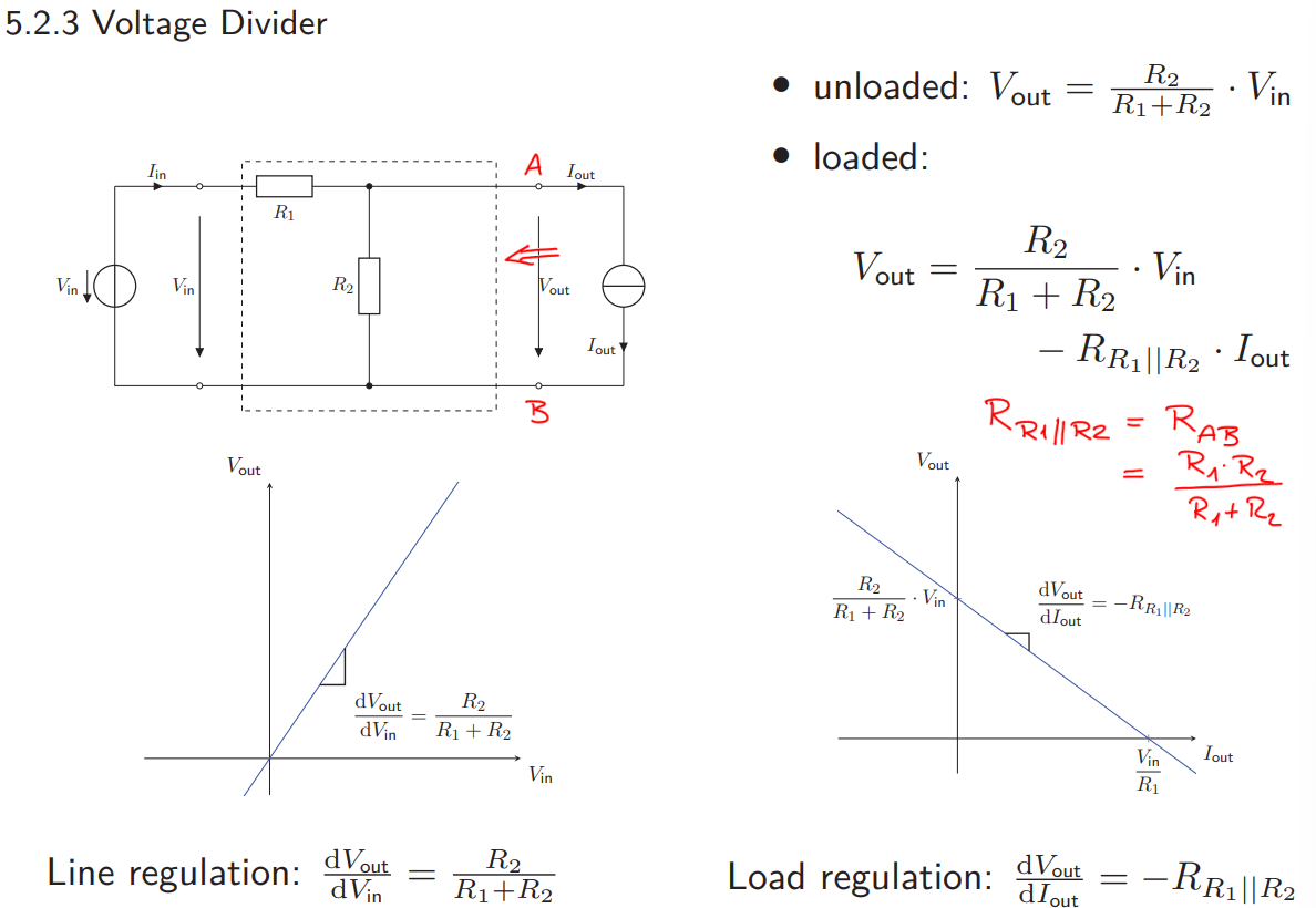
Voltage Divider (Regulator with Parallel Resistance)
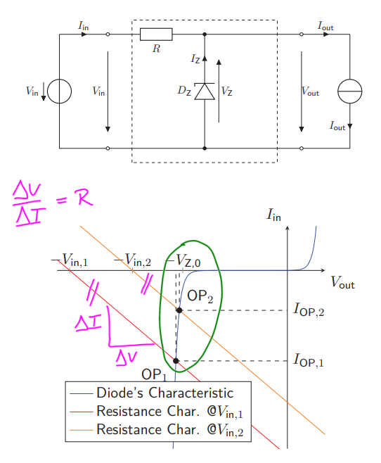
Regulator with Zener Diode
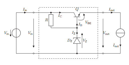
Regulator with Zener Diode and Transistor
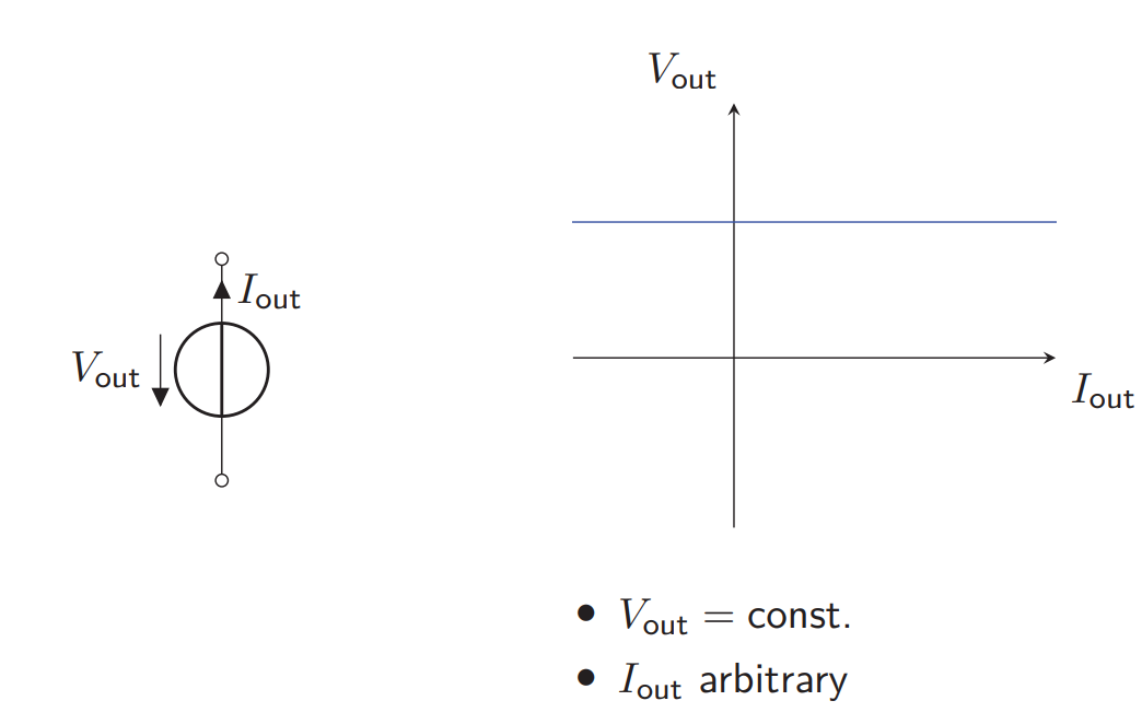
What is an Ideal Votlage Source in Power Electronics?
Constant Voltage regardless of the current through it
Zero Internal Resistance
Infinite Power Capability
How does a Voltage Source with Series Resistance look like?
How does a Voltage Divider look like?
How does a Voltage Regulator with Zener Diode looks like?
Uses the breakdown property of a Zener diode to regulate the voltage
How does a Voltage Regulator with Zener Diode and transistor looks like?
Improves the line and load regulations using the gain factor β of BJTs
What can MOSFETs be used for in Power Electronics?
As Unipolar Power Output Stage
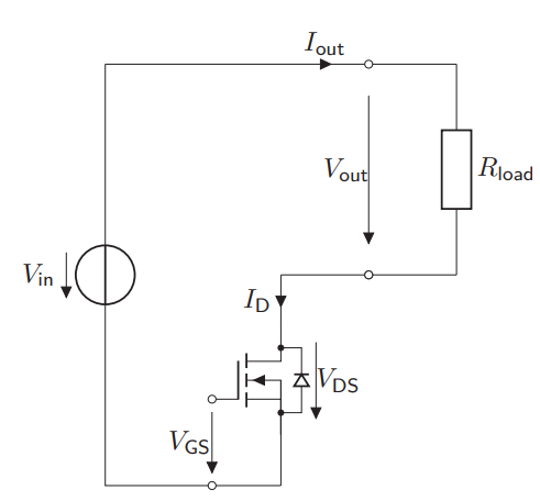
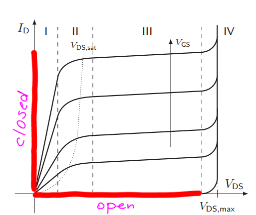
What is the characteristic of a MOSFET used as Unipolar Power Output Stage?
This basically means that a MOSFET in Power Electronics can be modelled by means of a switch
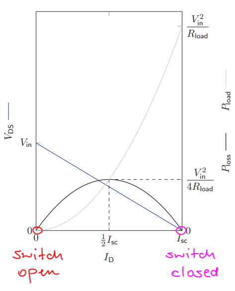
What is the characteristic of a MOSFET modelled by means of a switch?
Either is open or closed
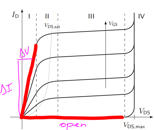
What is the characteristic of a MOSFET modelled by means of a Switch, a Resistor and a Diode?
Either open or with current flowing through the diode and scalated by the resistance
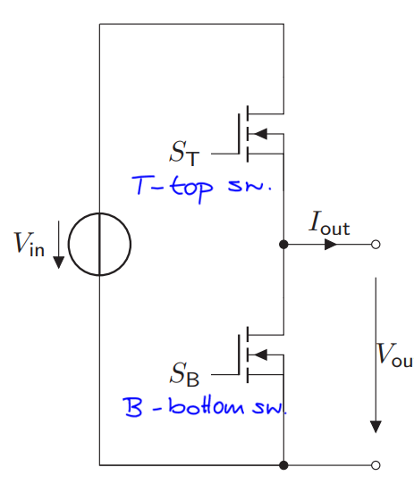
What is a half bridge?
Arrangement of two switches (MOSFETs or IGBTs) in series across a DC voltage source, in which the point between switches acts as the output terminal
Very low-loss operation possible
4 cases are possible:
Both ON = 1: short-circuit and destructive breakdown
Both OFF = 0: output voltage depending on the load connected to it and the circuits previous state
ST ON and SB OFF: output terminal connected directly to the positive terminal of the input voltage source. Therefore Vout = Vin
ST OFF and SB ON: Vout = 0
Basically, create AC out of a DC source by alternating states (creates a sqaure wave)
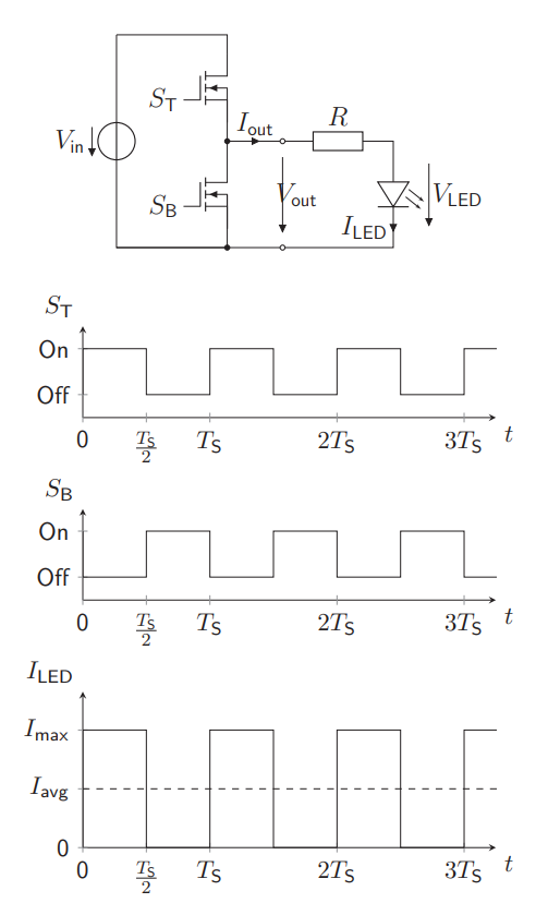
What is there to see about a Half Bridge + LED + Resistor?
Square current wave made from DC source to turn on the LED
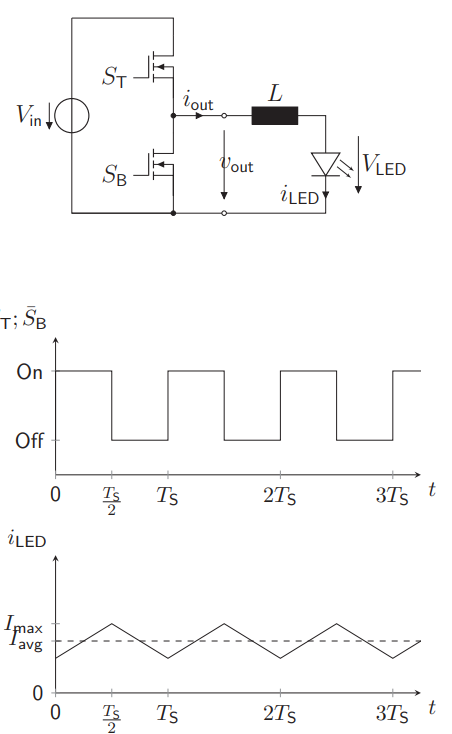
What is there to see about a Half Bridge + LED + Inductance?
Similar to the resistance variant, but with a traingular wave
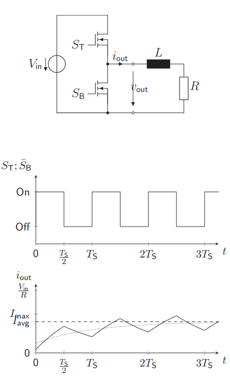
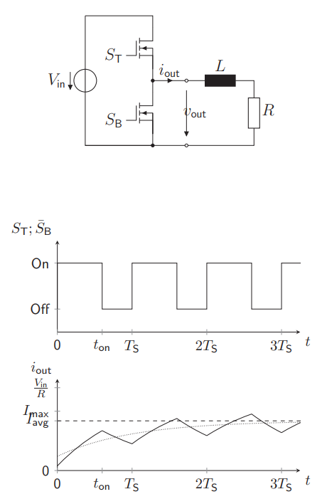
What is there to see about a Half Bridge + Inductance + Resistance?
Creates also a triangular current wave as a function of switching periods, due to the inductance resisting the current flow
Used as buck converter
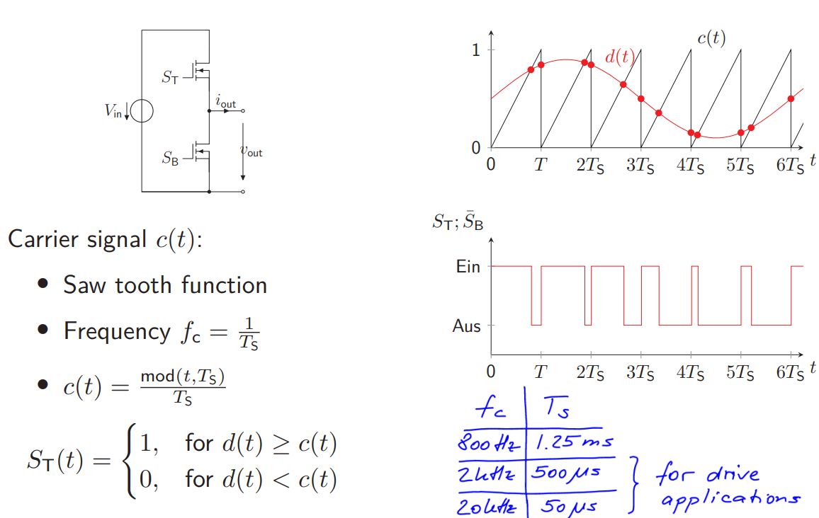
What is PWM?
Pulse Width Modulation
Lowers the average power delivered by a source by means of the duty cycle (percentage of time period in which the signal is ON)
Basically, alters the frequency of the power input by the source until the wanted output power is reached
How does the signal generation for PWM work?
A serrated carrier signal c(t) is compared with the modulating signal d(t), dividing the outputs at any point in 2 and therefore allowing to switch between states
c(t) > d(t) for a given t means OFF in switching terms
The same holds the other way around
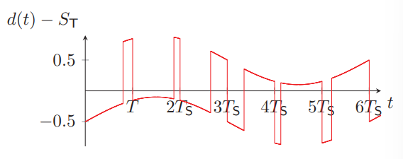
How is the error modelled?
As d(t) - ST
As a weird combination of square wave and trig wave
What are buck converters?
Power Electronics arrangements that can convert a DC voltage Vin to a lower Vout
They have synchronous and asynchronous embodiments

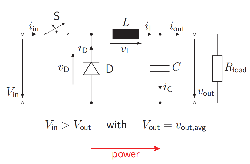
How is an asynchronous buck converter built? How does the characteristics of the asynchronous buck converter look like?
Switch + Diode + Inductance + Capacitor + Resistance
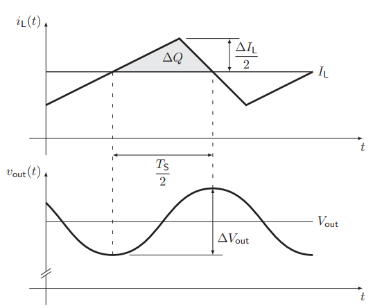
Chopped voltage signal, which is then converted into a smoot voltage signal due to the capacitor and the inductance (the capacitor smoothes the voltage, the inductance chops the current)
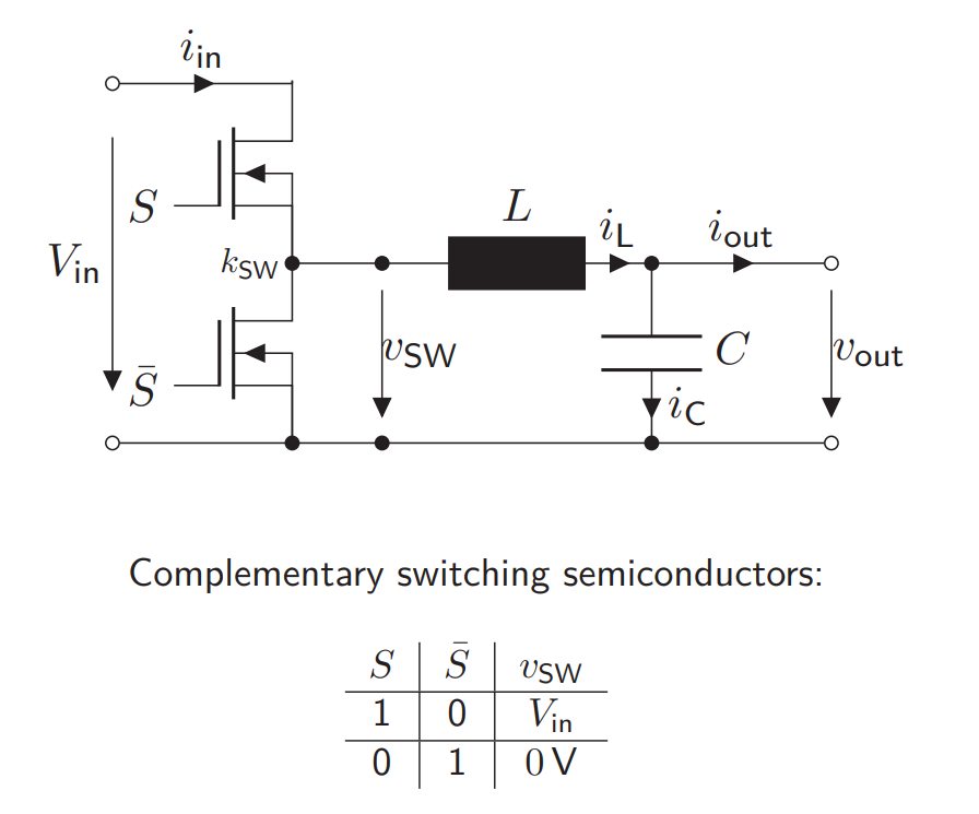
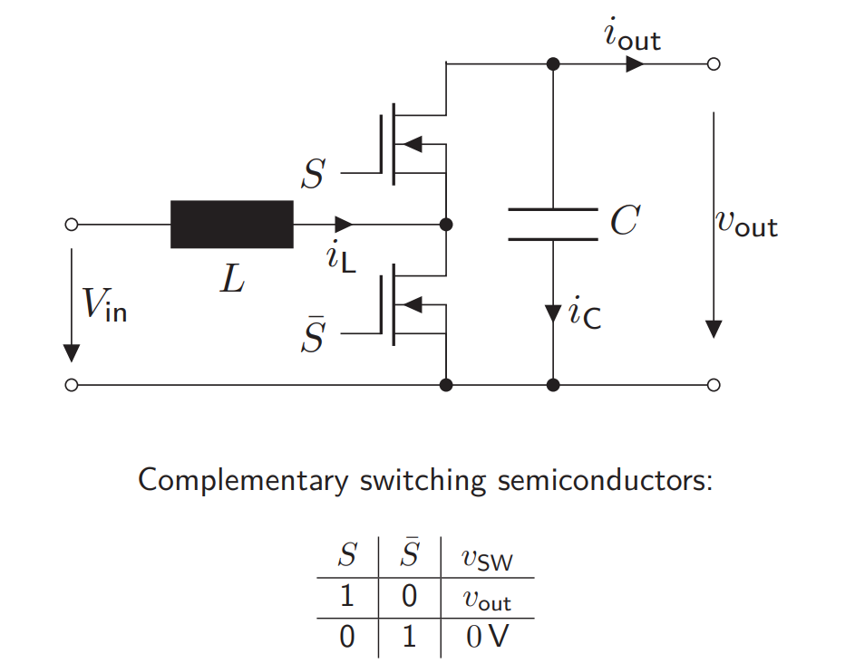
How is an synchronous buck converter built? How does the characteristics of the synchronous buck converter look like?
Half-Bridge + Resistance + Inductance + Capacitor
Provides lower ON-resistance that the asynchronous embodiment
Very complicated phase portraits inbetween
What are boost converters?
Power Electronics arrangements to ouput a voltage bigger than the input
As a mnemotic, switch, diode and inductance rotates one position counterclockwise to reach the boos configuration
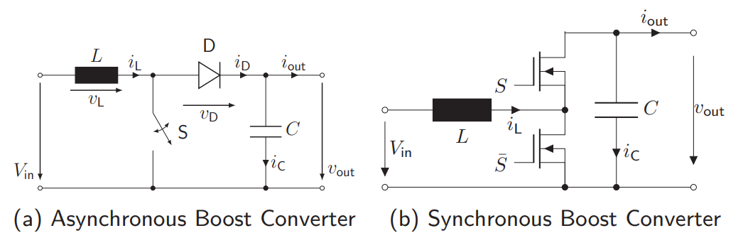
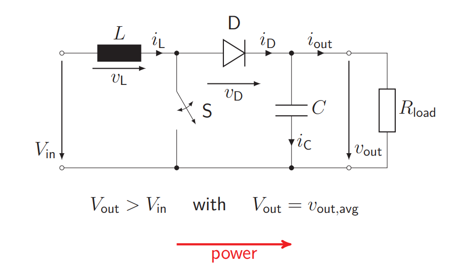
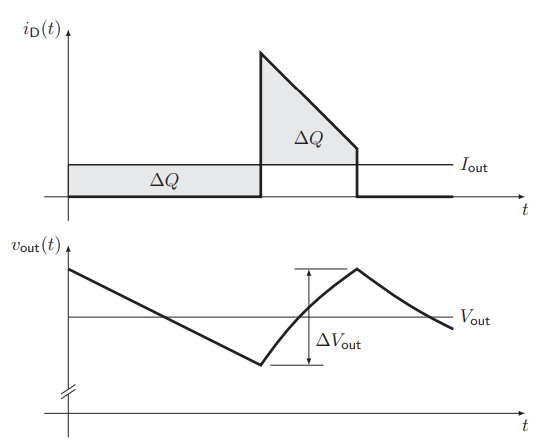
How is an asynchronous boost converter built? How does the characteristics of the asynchronous boost converter look like?
Inductance + Switch + Diode + Capacitor + Resistance
Ripple seen in the current graph, kinks in the voltage corresponding to the discontinuities of the current ripple
How is a synchronous boost converter built? How does the characteristics of the synchronous boost converter look like?
Inductance + Half-Bridge + Capacitor