Photon Therapy + Practical Patient Setup
1/40
There's no tags or description
Looks like no tags are added yet.
Name | Mastery | Learn | Test | Matching | Spaced |
|---|
No study sessions yet.
41 Terms
factors that cause deviation from inverse square relation
attenuation,
scattering, and
discrete sources which are not a point.
If you are far enough away from a discrete source it will still approximately act like a point source usually 2X the longest dimension would be appropriate.
Kilovoltage photon %DD curves surface dose
near 100% surface dose (as seen with the 3.0 mm Cu HVL curve).
PDD dependence on
SSD
FS
As SSD increases so does PDD
IVS built into PDD relationship
to decrease hotspot may want to increase SSD
As FS increases PDD increases - scatter
Equivalent square field formula
a = 4* A/P
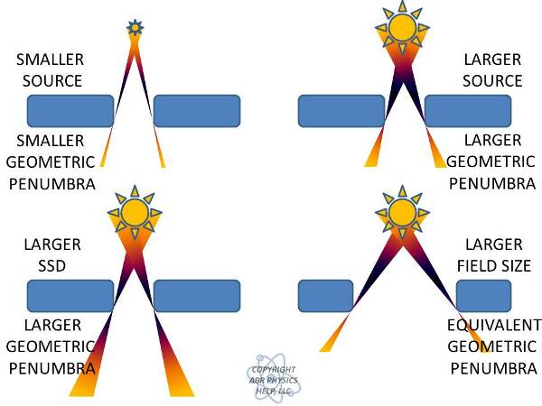
penumbra components and definition
Penumbra is composed of three components: geometric penumbra, transmission penumbra and scatter.
Penumbra is usually defined as the distance between the 80% and 20% isodose curves.
geometric penumbra - draw conceptually and give formula
GP = s(SSD+d-SCP)/SCD
s - is the source size (increases with source size).
SSD - is the source to skin distance (increases with SSD).
d - is the depth in the patient where penumbra is of interest (increases with depth).
SCD - is the source to collimator distance (decreases with SCD)
blocks away vs blocks on skin tradeoff
putting blocks on the patient will yield the sharpest penumbra, but you will lose skin sparing. You must keep the blocks about 20 cm away due to electron contamination ruining skin sparing.
transmission penumbra - define
Transmission penumbra is caused by differential attenuation through collimators or MLCs.
One way to help with this is to use divergent collimators that match the beam divergence.
Penumbra variation with Energy
In general, it is best for lower energy beams 6/10 MV and worse for higher energy beams 18/20 MV due to an increase in transmission penumbra.
Side scatter can also increase penumbra and as this decreases with increasing energy there is a competing effect.
The best balance between scatter and transmission penumbra occurs around 10 MV.
flatness: with FF what is the effect on profiles
Horns are required due to differential hardening in the flattening filter.
In the center, the beam is hardened and therefore penetrates more resulting in more fluence at 10 cm depth.
Near the periphery, the beam is not hardened as much and therefore is attenuated more than in the center. Therefore, it must have more fluence near the surface to achieve a uniform fluence at 10 cm depth.
where is flatness defined
inside of 80% of the field size at a depth of 10 cm.
what is adjusted when flatness or symettry are off
When symmetry or flatness is out (it is usually both at the same time), the beam is steered using solenoids so that it strikes the flattening filter in the middle yielding a nice uniform beam.
draw POP field PDD for Co-60. 6 MV, and 18 MV
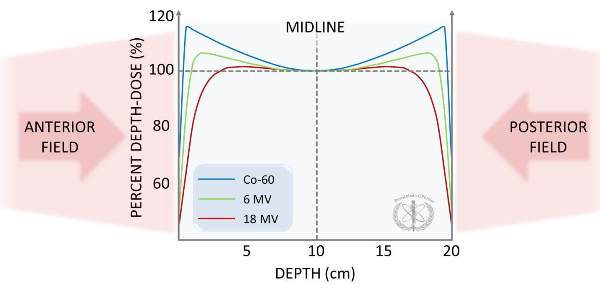
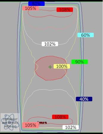
draw the profiles for POP
effects infront of, in, and after a beam incident on a slab of lung
Immediately in front of the lung, the dose will drop due to a lack of backscatter.
In the lung, the dose drops compared to water due to a lack of scatter.
If there is a solid tumor in the lung, then the beam must undergo build up similar to at the surface.
This is why it can be advantageous to use 6X during lung treatments for a smaller buildup length in a tumor.
Another reason 6X beams are commonly employed in lung treatments is that the lateral electronic equilibrium is better modeled by the algorithms that aren’t Monte Carlo based.
Beyond the lung, the dose will increase relative to water since there was little attenuation in the lung.
Lung will increase the penumbra of a beam due to the ability of scattered electrons to travel farther beyond the collimated field size. This effect worsens at higher energies, which is another reason for using 6X in lung treatments.
How to calculate the amount of increased attenuation
For example, if we have 5 cm of lung and want to know the difference in attenuation relative to a homogeneous water phantom.
5 cm * 0.33 yields an effective path length of 1.65 cm.
For a 6x beam attenuation in water is 3% per cm and for 18x it is 2% per cm.
So, for a 6x beam the expected attenuation in water would be 5 cm*3% = 15%, but with the lung in the beam the attenuation is only 1.65 cm*3% = 5%.
For a 6x beam, 5 cm of lung leads to about 10% of a heterogeneity correction (for 18x this would only be about 6.5%).
Important point: the higher the energy of the beam the less heterogeneity affects it.
Effect of bone slab on beam
Increased backscatter near the anterior interface leads to about an 8% increase in dose immediately adjacent to the bone in MV fields.
kV beams have as much as a 200% increase in dose due to the photoelectric effect.
Inside the bone (for MV beams), the dose to soft tissue, such as marrow, is expected to be higher than in water, but the dose to bone mineral (hard bone) is expected to be about 4% less.
The reduction in dose to the bone mineral is due to a lack of hydrogen content, this causes the electron density relative to mass to decrease resulting in a lower dose.
There is also a decrease in dose far from the bone due to increased attenuation.
In high energy photons beams (18/24 MV), increased pair production produces even higher doses around and inside the bone than seen above in the 6 MV image.
The density of bone is about 1.8 that of water, and this can be used to calculate a rough effect for bone attenuation in a beam similar to the discussion in lung.
Physical densities of
air
lung
water
bone
air - 0.0012 g/cm3
lung - 0.33 g/cm3
water - 1.0 g/cm3
bone - 1.8 g/cm3
Fluorescence method for measuring kVp
This method uses two chambers: one to measure transmission through an oblique absorbing material and one to measure scatter off of this material.
The voltage is adjusted until a maximum value of the ratio of the two chambers is seen.
This value corresponds to the K-edge.
Penetrameter method for measuring kVp
This method uses an experimental cassette containing a series of filters and a film that is exposed to the photon beam.
The exposed cassette is compared to a standard cassette to derive kVp information.
(This is mentioned for historical interest.)
kVp meter method of measuring kVp
The simplest way to measure kVp is to acquire a calibrated meter that you place in the beam and take an image.
These meters can instantly tell you the kVp and mAs of the beam for QA purposes.
definition of End Effects
dose rate dependencies for both Co-60 and LINACs when turning a beam on or off.
negligible for most LINACs but not for Co-60
describe the Clarkson/Cunningham method
based on the principle that the scattered component of the depth dose (which depends on field size and shape) can be calculated separately from the primary component which is independent of the field size and shape. We, therefore, may split TAR into two components: one representing the primary component of the beam, independent of field size and shape, and the other representing the scattered component of the beam, dependent on field size and shape
How do we correct from reference field size
multiply by field size correction factor: ScSp
define the wedge angle and the hinge angle
The Wedge Angle - is defined to be the angle through which an isodose curve is tilted at the central ray of a beam at the 10 cm depth.
The Hinge Angle - is defined to be the angle between the central axes of two beams (such as in a wedged pair treatment).
what is the formula for the optimal wedge angle in terms of the hinge angle
wedge = 90 - hinge/2
what is cerroband composed of?
bismuth, lead, tin
HVL for cerroband
approximately 1.5 cm for 6 MV photon beams and 1.8-2.0 cm for 18 MV photons.
what thickness needs to occur to effectively attenuate a beam
must attenuate a beam to approximately 3-5% (which is accomplished with about 5 HVLs). Thus, 7.5 to 8.0 cm of cerrobend would be needed to block a 6 MV photon beam.
rule of thumb to convert thickness of cerroband to thickness of lead

requirements of radiosurgery
Accurate knowledge of the target volume.
We have to be able to superimpose a 3D dose distribution over patient anatomy accurately.
We have to be able to accurately deliver dose to the target volume both numerically and spatially.
We have to be able to provide sharp dose gradients immediately outside the target volume.
cyberknife unique ability over gamma knife
Unlike the Gamma Knife, the CyberKnife can treat extracranially. The machine operates at about 600 MU/min.
MLC leakage approximate magnitudes
leaf transmission
interleaf
leaf end
Leaf Transmission Leakage (Intraleaf Leakage) - typically around 2%.
Interleaf Leakage - typically around 3-4%.
Leaf-End Leakage - typically around 15-20%.
what is DLG and how do we measure it
Physically, it is the leaf-end leakage and arises for each of the major MLC designs currently used in radiation oncology.
For Varian MLCs, the dosimetric (not physical) gap arises because we have MLCs with rounded leaf ends meeting from each bank. Even when the leaves are completely closed against each other, there is a substantial dose that can be measured as a thin strip where the leaves meet. The width of this strip is the DLG.
To Measure: 2 methods
Film:
With your calibrated film, make a series of exposures with varying physical leaf gaps between the leaves of the two banks (e.g. 2, 4, 6, 8, 10 mm, etc.).
Each gap should then have its own film.
Analyze these films to discover the full-width at half-maximum (FWHM) for each data point.
Plot FWHM versus leaf gap. This plot should be largely linear. Extrapolate your linear fit back to an FWHM of zero (i.e. the x-intercept). The absolute value of this x-intercept in mm will be your DLG.
Chamber:
The basic idea for this procedure is that you expose an open field and then you expose uniform fields that are made with sliding MLCs with varying leaf widths between banks A and B. As long as the MLCs move with constant speeds, there should be a uniform exposure made.
We repeat the uniform exposures for a series of leaf widths, and again, plot a detector reading (it could be film or a chamber).
By tracing the linear fit back to the x-intercept of chamber reading versus leaf gap width, the DLG can be measured as the absolute value of the x-intercept.
typical DLG value
1.5-2mm
Obese patient concerns with setup
weight limit differences by machine
skin folds: bad skin reactions possible
TIMO vs Silverman head rests
TIMO supports are made of polyurethane foam and come in a variety of sizes to attain the optimal comfort and head angulation/position.
Silverman head holders have similar variety and geometry but are made of a clear plastic that minimizes effects such as build-up and beam attenuation.
arms akimbo
This position has the patient position their arms on their hips.
Decubitus
The patient is positioned on their side.
Dorsal Recumbent
The patient is supine with knees bent and feet flat on table.
Frog Leg
The patient is in a supine position with their knees bent to either side.