DC to AC - Inverters

0.0(0)
studied byStudied by 0 people
0.0(0)
full-widthCall Kai
learnLearn
examPractice Test
spaced repetitionSpaced Repetition
heart puzzleMatch
flashcardsFlashcards
GameKnowt Play
Card Sorting

1/22

flashcard set

Earn XP

Description and Tags

Study Analytics
Name
Mastery
Learn
Test
Matching
Spaced

No study sessions yet.

23 Terms

1
New cards

What is the main function of an inverter?

To convert DC into AC.

2
New cards

Two main inverter categories?

Voltage-source (VSI) and current-source inverters (CSI).

3
New cards

What is a square-wave inverter?

An inverter that switches DC polarity to produce a square AC waveform.

4
New cards

What is a PWM inverter?

An inverter that uses Pulse-Width Modulation to approximate a sine wave.

5
New cards

Advantages of PWM inverters?

Lower harmonic distortion and controllable output voltage.

6
New cards

Typical devices in modern inverters?

MOSFETs or IGBTs.

7
New cards

Why are SCRs rarely used in PWM inverters?

They cannot be turned off by gate control and are slow for high-frequency PWM.

8
New cards

What is a pure sine wave inverter?

An inverter whose output closely matches a true sine wave.

9
New cards

What is a modified sine wave inverter?

A stepped approximation of a sine wave with higher harmonics.

10
New cards

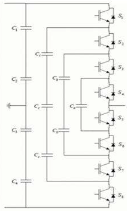
What is a multilevel inverter?

Inverter synthesizing AC from multiple DC levels for smoother output.

11
New cards

List three multilevel inverter types.

Diode-clamped (NPC), Flying capacitor, Cascaded H-bridge.

12
New cards

Advantage of multilevel vs two-level?

Lower dv/dt, reduced harmonics, better efficiency.

13
New cards

How is PWM generated?

Compare high-frequency triangular carrier with sinusoidal reference; switch when reference exceeds carrier.

14
New cards

Inverter applications?

UPS, renewable energy systems, motor drives.

15
New cards

Describe PWM control waveforms.

Triangular carrier compared with sine reference; pulses widen near peaks and narrow near zero crossings.

<p>Triangular carrier compared with sine reference; pulses widen near peaks and narrow near zero crossings.</p>
16
New cards

Describe three-phase inverter output.

Three 120-degree-shifted PWM phase voltages; line-to-line voltage forms stepped near-sine.

<p>Three 120-degree-shifted PWM phase voltages; line-to-line voltage forms stepped near-sine.</p>
17
New cards

Describe multilevel inverter output.

Multiple small voltage steps per half-cycle produce a near-sinusoidal waveform.

<p>Multiple small voltage steps per half-cycle produce a near-sinusoidal waveform.</p>
18
New cards
Voltage Source Inverter (VSI)
A Voltage Source Inverter maintains a **constant DC voltage** at its input.
The output voltage waveform is controlled using switches (e.g., MOSFETs or IGBTs).
It is the most common inverter type, used in variable-speed drives and grid-tied systems.
A Voltage Source Inverter maintains a **constant DC voltage** at its input.  
The output voltage waveform is controlled using switches (e.g., MOSFETs or IGBTs).  
It is the most common inverter type, used in variable-speed drives and grid-tied systems.
19
New cards
Current Source Inverter (CSI)
A Current Source Inverter maintains a **constant input current**, using large inductors to smooth current.
The output current waveform is controlled, making it suitable for current-driven loads such as induction heating or certain motor drives.
A Current Source Inverter maintains a **constant input current**, using large inductors to smooth current.  
The output current waveform is controlled, making it suitable for current-driven loads such as induction heating or certain motor drives.
20
New cards
Diode-Clamped (Neutral-Point Clamped) Multilevel Inverter
This type uses diodes to clamp voltage levels across the switches.
It divides the DC bus into multiple voltage steps, producing a stepped waveform with reduced harmonics.
It’s common in medium-voltage, high-power industrial drives.
This type uses diodes to clamp voltage levels across the switches.  
It divides the DC bus into multiple voltage steps, producing a stepped waveform with reduced harmonics.  
It’s common in medium-voltage, high-power industrial drives.
21
New cards
Cascaded H-Bridge Multilevel Inverter
This inverter consists of multiple H-bridge units connected in series, each supplied by a separate DC source.
Each bridge generates three voltage levels (+V, 0, −V).
It provides modular design and scalability but requires isolated DC supplies.
This inverter consists of multiple H-bridge units connected in series, each supplied by a separate DC source.  
Each bridge generates three voltage levels (+V, 0, −V).  
It provides modular design and scalability but requires isolated DC supplies.
22
New cards
Flying Capacitor Multilevel Inverter
This inverter uses capacitors in series to generate multiple voltage levels.
Each level is created by charging or discharging specific capacitor combinations.
Advantages include redundant switching states and better voltage balancing, but control is more complex.
This inverter uses capacitors in series to generate multiple voltage levels.  
Each level is created by charging or discharging specific capacitor combinations.  
Advantages include redundant switching states and better voltage balancing, but control is more complex.
23
New cards
Advantages of Multilevel Inverters
• Lower harmonic distortion
• Reduced electromagnetic interference (EMI)
• Higher efficiency at lower switching frequencies
• Can handle higher voltage with standard devices #