Topic 3: Electric Circuits
1/48
There's no tags or description
Looks like no tags are added yet.
Name | Mastery | Learn | Test | Matching | Spaced |
|---|
No study sessions yet.
49 Terms
Electric charge
SI unit is coulomb (C)
Symbol is Q
Electric current
Rate of flow of charged particles
Occurs when a charged particle that is free to move experiences an electric force that accelerates it.
SI unit is ampere (A)
Symbol is I
I = ΔQ / Δt (current = charge passing a point / time for that charge to pass)
Conventional current vs flow of electrons
Conventional current is the direction in which positive charge would move, which is from positive to negative
Electrons flow from negative to positive
Voltage / potential difference
The amount of energy that each unit of charge transfers between two points on a circuit
SI unit is volt (V) which is 1 J/C
Symbol is V
V = W / Q (potential difference = energy transferred / charge passing)
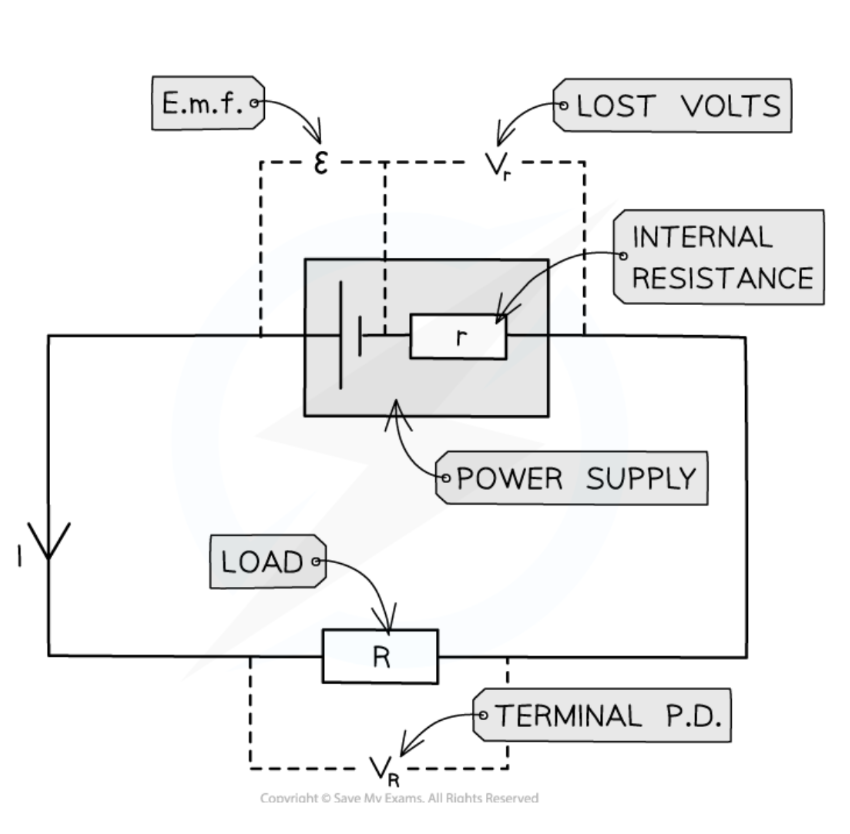
Electromotive force
The amount of chemical energy converted to electrical energy that is transferred to each unit of charge that passes through a power supply.
SI unit is volt (V)
Symbol is 𝜖
𝜖 = IR + Ir (where R = load resistance, r = internal resistance, IR = terminal potential difference, and Ir = lost volts)
Measuring potential difference
Measured with a voltmeter
Must be connected in parallel to a device
Potential difference and current relationship
For a fixed resistance, current and potential difference are directly proportional.
R = V / I (resistance = potential difference / current)
Resistance
The opposition to the flow of electrical current as a result of collisions between the electrons and the atoms of the conductor in its path.
SI unit is Ohm (Ω) which is 1 V/A
Symbol is R
R = ⍴l / A (resistance = (resistivity x sample length) / cross-sectional area)
How changes in potential difference and resistance affect current
Increase in potential difference causes an increase in current.
Increase in resistance causes a decrease in current.
Ohm’s law
States that the current through an ohmic conductor is directly proportional to the potential difference across it, providing the temperature remains constant.
The graph is a straight line through the origin.
V = IR
Electric current rule
The total current flowing into a junction is equal to the total current flowing out of that junction due to charge conservation.
Current in a parallel circuit
The current divides at a junction, with each branch having a different value.
The current before a junction is equal to the sum of the currents after the junction.
Current in a series circuit
The current is the same at all points.
I-V graph
The voltage is plotted on the x-axis and the current is plotted on the y-axis
The resistance is the reciprocal of the gradient
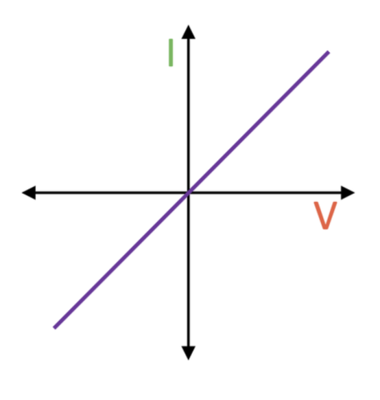
I-V graph for an ohmic conductor
A straight line with positive gradient through the origin
I-V graph for a filament bulb
For small voltages, current is proportional to voltage.
As the voltage increases, the current increases, resulting in an increase of temperature, increasing the resistance of the component, reducing the current and resulting in a curve with a decreasing gradient.
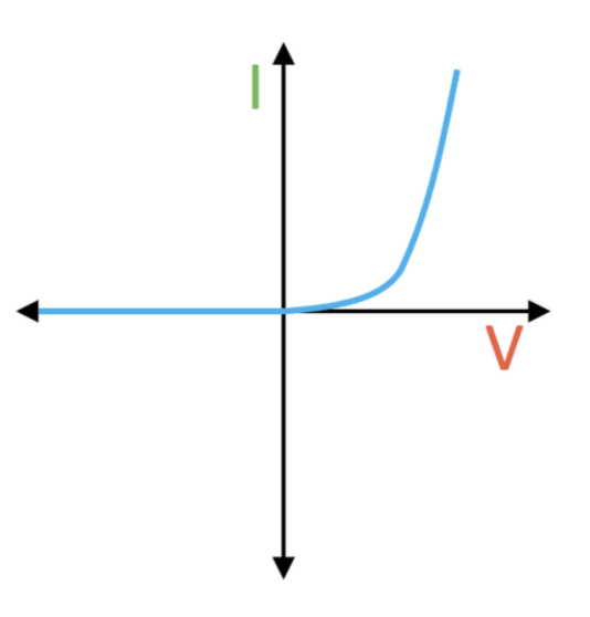
I-V graph for a diode
The resistance is very high for negative voltages, as diodes only allow current to flow in the forward direction.
Diodes require a minimum voltage in the forward direction, and there is a significant current at this voltage.
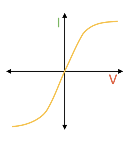
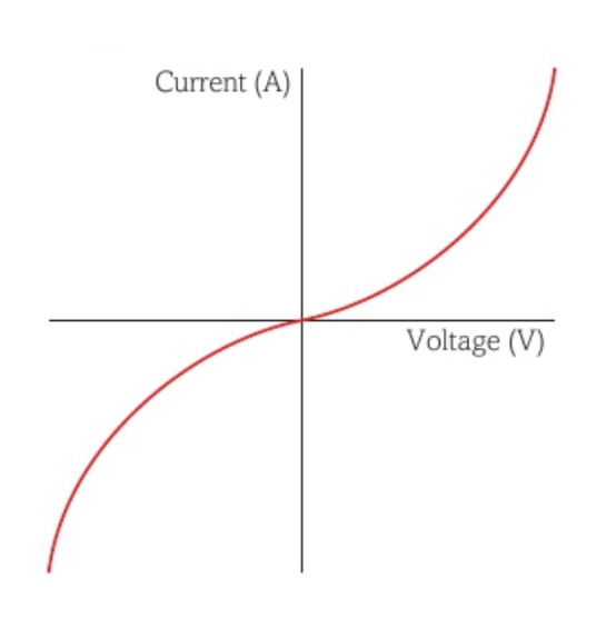
I-V graph for a negative temperature coefficient thermistor
Negative temperature coefficient thermistors decrease in resistance when the temperature increases.
Thus, as the voltage increases and the current increases and the temperature increases and the resistance decreases, the current also increases, resulting in a curve with an increasing gradient.
The graph can be interpreted as the reverse of the one for a filament bulb.
Resistivity
The value of resistance between opposite faces of a cubic metre of a material.
SI unit is Ωm
Symbol is ⍴
Electrical voltage rule
The sum of the EMFs in a closed circuit loop is equal to the sum of the potential differences around the loop due to energy conservation.
Potential difference in a parallel circuit
The sum of the voltages in each closed circuit loop is equal to the total EMF of the power supply.
Potential difference in a series circuit
The sum of the potential differences across the components is equal to the total EMF of the power supply.
Resistance in a series circuit
The combined resistance of the components is equal to the sum of the individual resistances.
RT = R1 + R2+ ... + Rx
Deriving the equation for resistance in a series circuit
The total potential difference across x components in series is the sum of the potential differences across each component: VT = V1 + V2 + ... + Vx → IRT = IR1 + IR2 + ... + IRx
The total current across x components in series is equal to the current across each component: IT = I1 = I2 = Ix
Since current is constant, divide IR = IR1 + IR2+ ... + IRx by I to get R = R1 + R2 + ... + Rx
Resistance in a parallel circuit
The reciprocal of the combined resistance of the components is equal to the sum of reciprocals of the individual resistances.
1/R = 1/R1 + 1/R2 + ... + 1/Rx
Deriving the equation for resistance in a parallel circuit
The total current across x components in parallel is the sum of the currents across each component: IT = I1 + I2 + ... + Ix → V/RT = V/R1 + V/R2 + ... + V/Rx
The total potential difference across x components in parallel is equal to the potential difference across each component: VT = V1 = V2 = Vx
Since potential difference is constant, divide V/RT = V/R1 + V/R2 + ... + V/Rx by V to get 1/RT = 1/R1 + 1/R2 + ... + 1/Rx
Work done by a component in an electric circuit
W = VIt (work done = potential difference x current x time)
Deriving the equation for work done by a component in an electric circuit
I = Q / t so Q = It
V = W / Q so W = VQ
Substitute equation 1 into equation 2: W = VIt
Power of a component in an electric circuit
P = VI (power = potential difference x current)
Deriving the equation for power of a component in an electric circuit
P = W / t
W = VIt
Substitute equation 2 into equation 1: P = VIt / t → P = VI
Power of a component in an electric circuit in terms of resistance
P = I2R
P = V2 / R
Deriving the equation for the power of a component in an electric circuit in terms of resistance
P = VI
V = IR
Substitute equation 2 into equation 1: P = I2R
P = VI
V = IR so I = V / R
Substitute equation 2 into equation 1: P = V2 / R
Drift velocity
The average velocity of charge carriers travelling through a conductor.
In conductors, free electrons move randomly and collide with the metal ions of the conductor.
When there is an emf across the conductor, the free electrons have a net movement or drift velocity towards the positive end of the electric field.
When the charge carriers are positive, the drift velocity is in the same direction as the conventional current.
When the charge carriers are negative, the drift velocity is in the opposite direction to the conventional current.
Transport equation
The current in a conductor can be expressed using the transport equation: I = nqvA (current = number density of charge carriers x charge of the charge carrier x drift velocity x cross sectional area of the conductor)
Resistivity of different materials
Different materials have different values of n (number density of charge carriers).
Materials with higher values of n have lower resistivities, as the current will be greater for the same applied potential difference.
Conductors such as metals have a high value of n and a low resistivity because they have free electrons.
Insulators have a very low value of n and a high resistivity because they have no free electrons.
Semiconductors have variable values of n at different temperatures, with higher temperatures resulting in higher values of n and a lower resistivity.
Potential difference along a uniform current-carrying wire
Using R = pl / A, it can be seen that a greater length of wire results in a greater resistance.
Using V = IR, it can be seen that a greater resistance for a constant current results in a greater potential difference across the wire.
Thus, the potential difference along a uniform current-carrying wire increases uniformly with the distance along it.
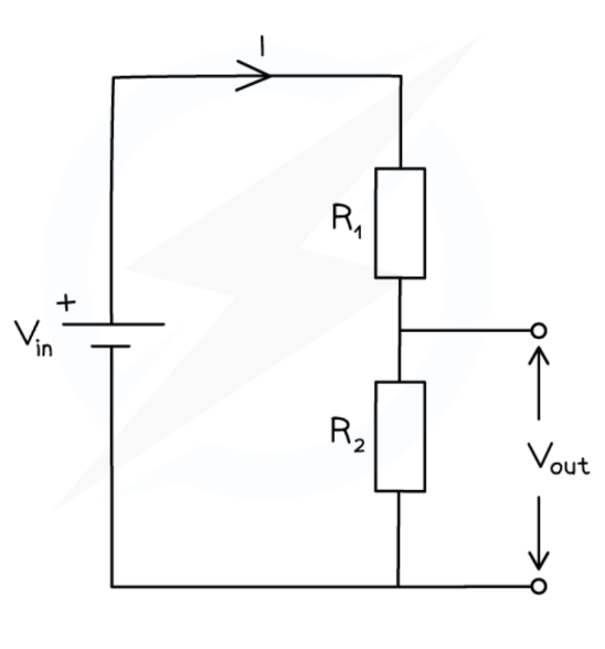
Potential dividers
Circuits that produce an output potential difference as a fraction of the input potential difference by using two resistors in series to divide the potential difference between them.
The resistor with the largest resistance will have the greatest potential difference across it due to V = IR
Vout = Vin x (R2 / (R1 + R2))
V1 / V2 = R1 / R2
Potential divider purpose
To provide a variable output potential difference by using a variable resistor
To choose a specific output potential difference
To split the potential difference of a power supply between multiple components
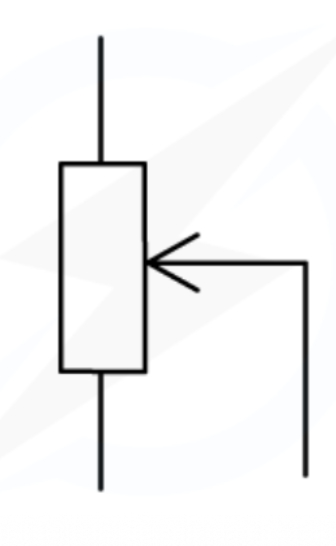
Potentiometer
A single component that can act as a potential divider, consisting of a coil with a sliding contact.
The sliding contact separates the potentiometer into two parts, each with different resistances and therefore potential differences.
If the slider moves upwards, the resistance of the lower part will increase and therefore the potential difference of the lower part will increase.
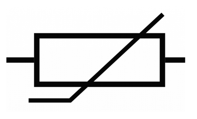
Negative temperature coefficient thermistor
A component that decreases in resistance with an increasing temperature.
Potential divider circuit involving negative temperature coefficient thermistors
A variable potential difference can be created in a circuit using a thermistor.
When the temperature increases, the resistance of the thermistor decreases and the potential difference across it decreases.
This increases the potential difference across the other resistor.
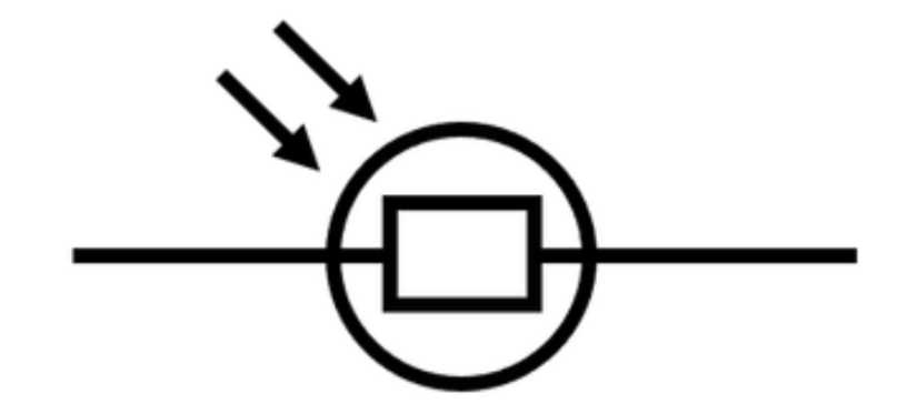
Light-dependent resistors
A component that decreases in resistance with an increasing light intensity.
Potential divider circuit involving light-dependent resistors
A variable potential difference can be created in a circuit using a light-dependent resistor.
When the light intensity increases, the resistance of the light-dependent resistor decreases and the potential difference across it decreases.
This increases the potential difference across the other resistor.
Internal resistance
The resistance between the terminals of a power supply that causes some electrical energy to be converted to thermal energy, resulting in lost volts due to electrons colliding with the atoms of the power source.
It can be represented by a resistor connected in series inside the power source.
The amount of lost volts is greater with a higher current.
Lost volts = Ir (where r = internal resistance)
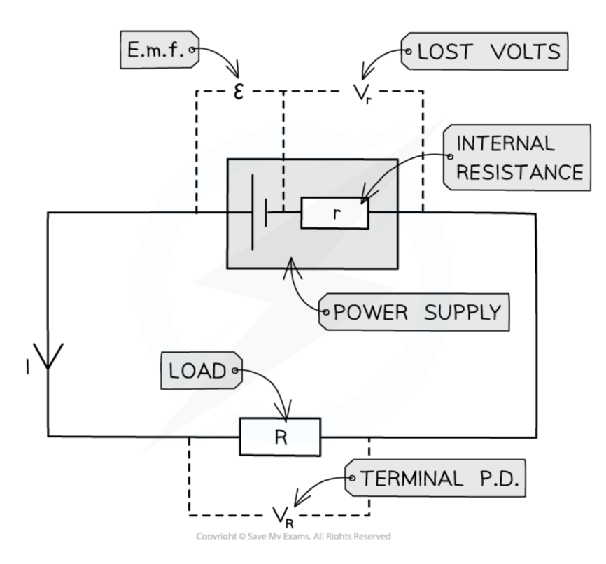
Terminal potential difference
The potential difference across the terminals of a cell, which is lower than its EMF.
Terminal potential difference = EMF - lost volts
The terminal potential difference is equal to the potential difference across the load, as parallel branches have the same voltage across them.
Explanation of how increased temperature increases resistance
When temperature increases, lattice vibrations of ions in a conductor have a greater amplitude, increasing the frequency of collisions between the free electrons and the lattice ions of the conductor.
This causes the rate of flow of electrons to decrease, so the resistance of the conductor increases.
Explanation of how increased current increases temperature
A greater current causes a greater frequency of collisions between the free electrons and lattice of ions of the conductor.
This causes the ions of the conductor to vibrate more, increasing its temperature.
Explanation of how increased temperature decreases resistance in negative temperature coefficient thermistors
When temperature increases, the number density of conduction electrons in thermistors increases, as more energy is transferred to the lattice ions, with their electrons gaining energy and allowing them to break free from the atoms.
Since I = nqvA, when the number density of conduction electrons increases, the current increases.
Since R = V / I, when the current increases, the resistance of the thermistor decreases.
Explanation of how increased light intensity decreases resistance in light-dependent resistors
When light intensity increases, the LDR absorbs the light, transferring energy to the electrons, and the number density of conduction electrons in light-dependent resistors increases.
Since I = nqvA, when the number density of conduction electrons increases, the current increases.
Since R = V / I, when the current increases, the resistance of the LDR decreases.