3B1 VCVS & Filters & Oscillators
1/23
There's no tags or description
Looks like no tags are added yet.
Name | Mastery | Learn | Test | Matching | Spaced | Call with Kai |
|---|
No analytics yet
Send a link to your students to track their progress
24 Terms
Wein Bridge oscillator circuit schematic?
Describe what Colpitts oscillator is?
And frequencies that can be achieved?
LC resonant circuit with transistor as the active element driving the oscillations
Frequencies up to several GHz achieved
What makes an op-amp ideal?
No current drawn by the inputs
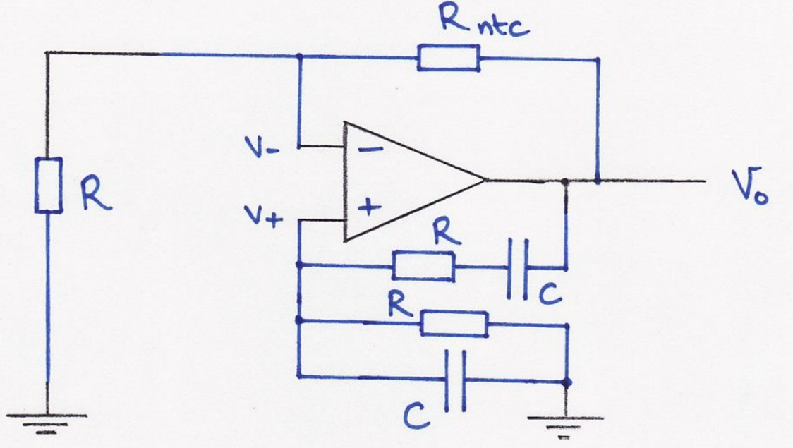
How to make high-pass filter VCVS?
And how to make bandpass?
High-pass: switch Rs and Cs from low-pass diagram
Bandpass: cascade overlapping low-pass and high-pass stages
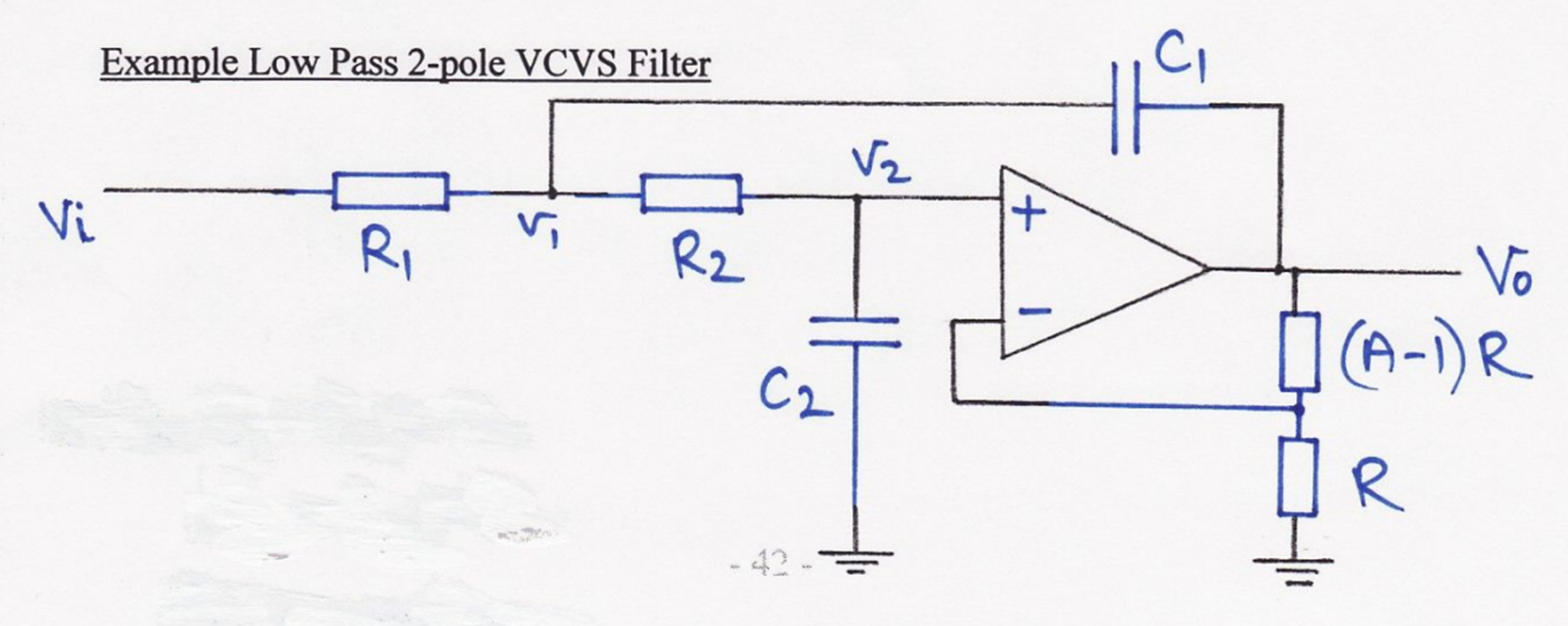
Low-pass 2 pole single stage VCVS filter circuit schematic?
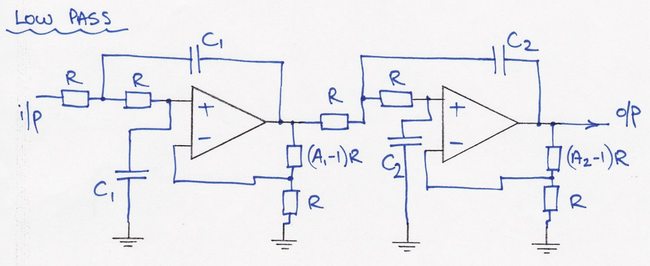
Low-pass 2 pole, 2stage VCVS filter circuit schematic?
Standard E12 values?
1, 1.2, 1.5, 1.8, 2.2, 2.7, 3.3, 3.9, 4.7, 5.6, 6.8, 8.2
What is fc?
cut-off (-3dB) freq
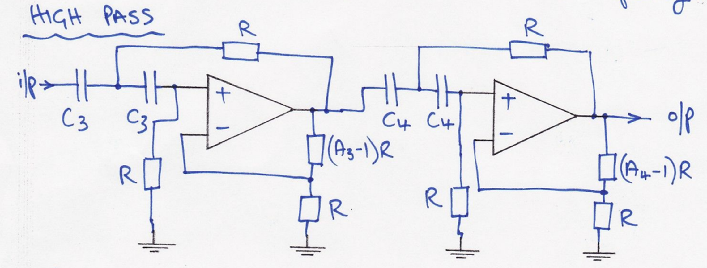
High-pass 2 pole, 2stage VCVS filter circuit schematic?
What are poles in filter design?
Frequencies where the gain drops sharply
(when transfer function’s denominator goes to zero)
Each opamp creates 2 poles
Natural frequencies from how R & C interact in each stage
High-pass fc and gains in 4 pole VCVS?
Swap Rs and Cs → fn becomes 1/fn
OpAmp gains are same for poles 1&3 and 2&4
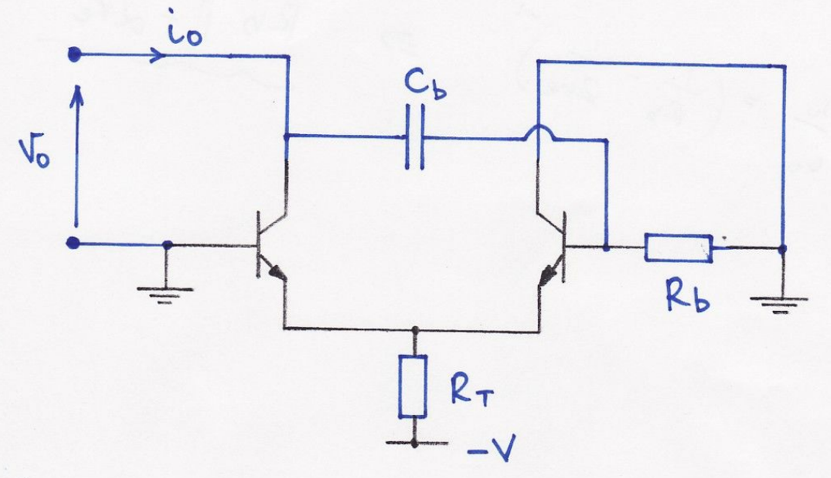
Negative impedance oscillator circuit schematic?
When to choose each of the VCVS filters?
Bessel: e.g. shaped electrical pulses
fixed time delay, no overshoot, good time domain response
↑ best for passing transients undistorted
PULSE SHAPE RETENTION BUT REDUCED SHARPNESS
Chebyshev: steep cut-off
best frequency cut-off but distorts waveform shapes
Butterworth: reasonably good cut-off without significant overshoot
a fair all rounder
compromise between the other two
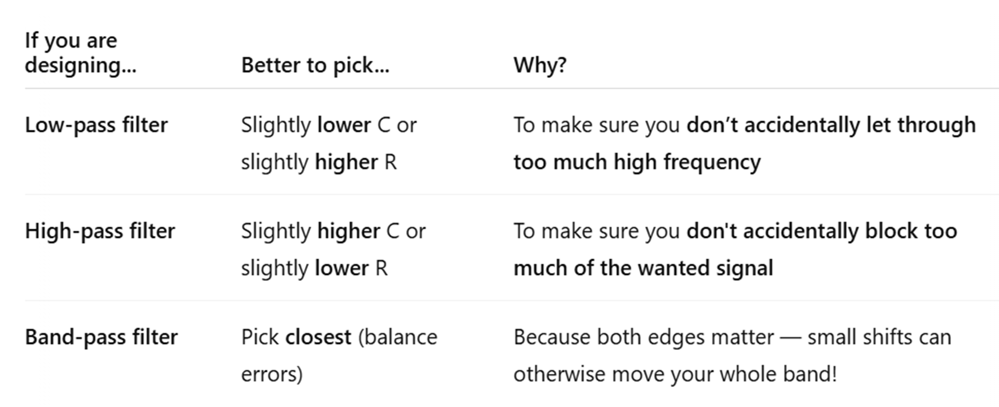
Should you pick higher or lower R & C standard values in low-pass, high-pass and bandpass filters?
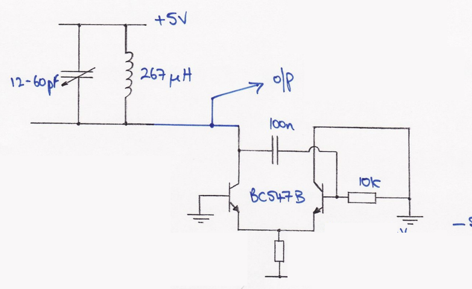
How does a negative impedance oscillator work?
by cancelling the resistive losses in an LC circuit with a transistor to create sustained oscillations
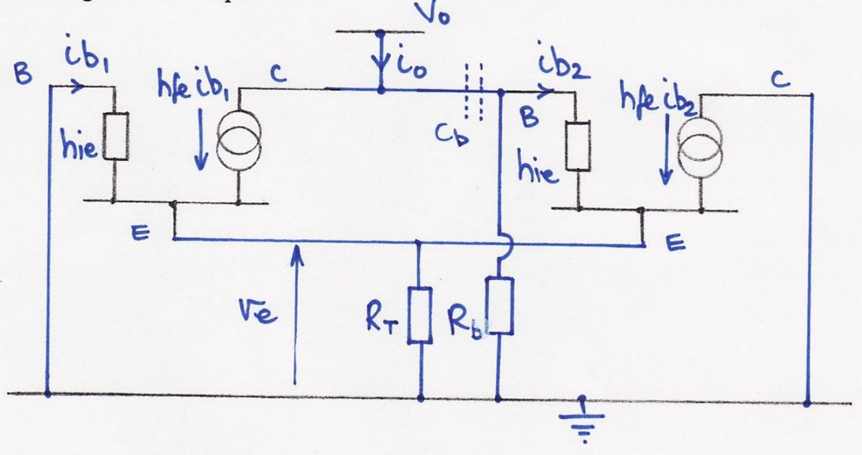
Steps to draw -ve impedance oscillator SSM?
draw both transistors
connect Es
first B & second C to ground
RT from common E to ground
Rb from common C/B to ground
Vo above both transistors (with io going down into common B/C)
Cb dashed in common C/B
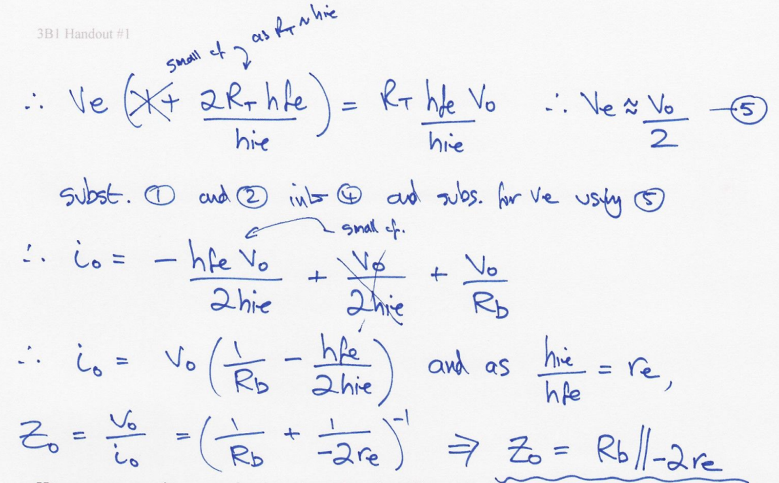
Main result from -ve impedance oscillator SSM?
Zo = Rb // (-2 re)
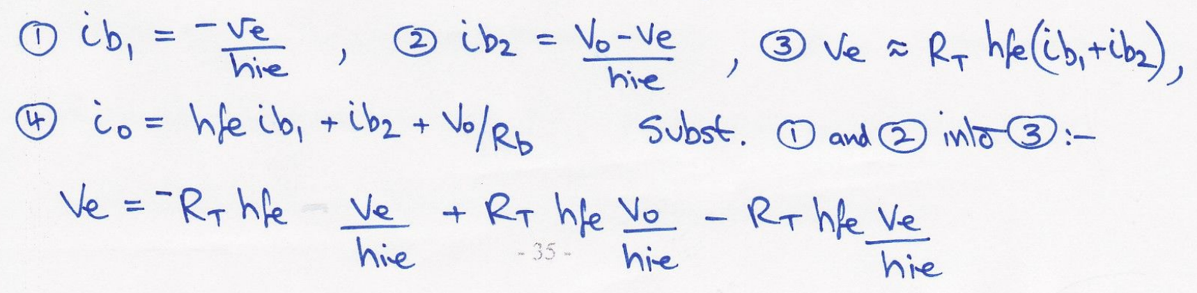
Steps to find -ve impedance oscillator result?
Why do we want to add a resistance to -ve impedance oscillator?
to cancel out resistive parasitic component of LC combination
Circuit schematic of -ve impedance oscillator with LC resonant tank circuit?
How to find parasitic loss resistance of -ve impedance oscillator?
wLQ
[Q = Q factor]
Rule to find Rb from inductor parasitic R & -ve transistor R?

Want overall resistance to be -ve and less than 0.5 RL, but same order of magnitude
Ic in -ve impedance oscillator?
Ic = ½ (5 - 0.6) / RT