Earthing & Faults
1/9
There's no tags or description
Looks like no tags are added yet.
Name | Mastery | Learn | Test | Matching | Spaced | Call with Kai |
|---|
No analytics yet
Send a link to your students to track their progress
10 Terms
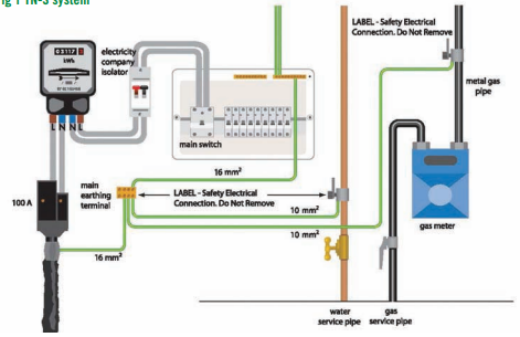
What is a TNS system, what is its disconnection time and what is its earth fault loop impedance?
T = Terra (earth connected at the source)
N = Neutral connected to earth at the source
S = Separate earth and neutral conductors
In a TN-S system, the line and neutral are provided as separate conductors from the supply transformer, and the earth is provided by the metal sheath of the supply cable, which is earthed at the source to provide a path for fault current.
The maximum disconnection time is 0.4 seconds for final circuits and 5 seconds for distribution circuits. These disconnection times apply regardless of whether an RCD is used, although an RCD may be required to achieve these times.
Typical external earth fault loop impedance (Ze) value is around 0.8Ω
What is a TN-C-S system, what is its disconnection time and what is its earth fault loop impedance?
Terra-Neutral-Combined-Separate
In a TN-C-S system, the supply provides a line conductor and a combined protective earth and neutral (PEN) conductor from the transformer to the service head. At the service head, the PEN conductor is separated into neutral and earth. This system is also known as PME (Protective Multiple Earthing), as the neutral is earthed at multiple points along the supply network. In the event of a fault, current flows through the circuit protective conductor (CPC) and returns via the PEN conductor to the source, causing the protective device to disconnect the supply.
The maximum disconnection time is 0.4 seconds for final circuits and 5 seconds for distribution circuits. These times apply regardless of whether an RCD is used, although an RCD may be required to achieve them.
Typical external earth fault loop impedance value is around 0.35Ω
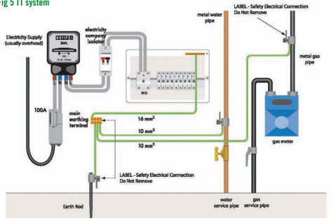
What is a TT system, what is the disconnection time and what is its earth fault loop impedance?
First T = The transformer neutral is connected to Terra (earth) at the source
Second T = The installation is connected to its own local earth (Terra) via an earth rod.
In a TT system, the supply provides a line and neutral conductor only, and the installation earth is connected to a local earth electrode, such as a rod or plate, rather than the supply earth. In the event of a fault, current flows through the earth electrode and returns through the general mass of earth to the source. Due to the high earth loop impedance, an RCD is required to provide automatic disconnection of supply.
The maximum disconnection time is 0.2 seconds for final circuits and 1 second for distribution circuits when protected by an RCD.
Typical external earth fault loop impedance value is around 200Ω
What is the difference of PEN and PME for a TNC-S system?
PEN - (Protective earth neutral) Combines neutral and earth conductor
PME - (Protective multiple earths) The system using pen conductor with multiple earthing points.
What is the external and normal (Zs)earth fault loop impedance test?
Zs (earth fault loop impedance) is measured at the furthest point of a circuit and represents the total impedance of the earth fault loop, including the supply and installation. It verifies that the fault current path is low enough to allow protective devices (such as fuses or circuit breakers) to disconnect the supply quickly under fault conditions. The test is carried out with the circuit energised using an RCD-compatible loop impedance tester connected between line and earth, and the measured value is compared with the maximum permitted value. A low Zs value ensures sufficient fault current flows for fast disconnection.
Zs can also be calculated using:
Zs = Ze + (R1 + R2
Where:
Ze = external earth loop impedance (supply side)
R1 = line conductor resistance
R2 = CPC (earth) resistance
Ze (external earth fault loop impedance) is measured at the origin of the installation and represents the impedance of the supply earth path only. To measure Ze, the main earthing conductor is temporarily disconnected to avoid parallel paths. A loop impedance tester is connected between line and earth, and the reading is taken. The earthing conductor must be reconnected immediately after the test.
R1 + R2 is the resistance of the line conductor and circuit protective conductor within the installation. It is measured on a dead circuit using a continuity tester and is used to help calculate Zs.
What is prospective fault current?
The purpose of a PFC test is to determine the maximum possible fault current at a point in the installation to ensure protective devices can safely withstand and disconnect it. Both are measured by a PFC tester sometimes called a fault loop tester. (often part of a MFT).
The prospective short circuit current (Pscc) is the maximum current that could flow between line and neutral conductors on a single phase supply or between line conductors on a three phase supply.
The prospective earth fault current (Pefc) is the maximum current that could flow between live conductors and earth.
The higher of these two values will be noted down on schedule of test results and as the prospective fault current (PFC). Both measurements are in kA (Kilo amps) so thousands of amps as a result. PFC calculation is fault current + voltage / Ze or I = V / Ze. However, if its a 3 phase supply square root it by 3.
What is continuity of CPC and how is it done?
The continuity of protective conductors test is carried out to verify that the circuit protective conductor (CPC) is continuous and correctly connected throughout the circuit. With the supply safely isolated, a low resistance ohmmeter/continuity tester (usually on a MNT) (minimum 200 mA test current) is used. The line conductor and CPC are temporarily linked together at the distribution board, and the resistance is measured between line and earth at the furthest point of the circuit. The measured value represents R1 + R2 (the resistance of the line conductor plus the CPC). A low resistance reading confirms that a continuous fault path exists, ensuring that sufficient fault current can flow to enable automatic disconnection of supply in the event of a fault.
What is continuity of bonding conductors test method 1 and how is it done?
The continuity of bonding conductors test (Method 1) is used to confirm that main protective bonding conductors connecting extraneous conductive parts (such as gas and water services) to the main earthing terminal (MET) are continuous and effective. After safely isolating the supply, the bonding conductor remains connected in place. Using a low-resistance ohmmeter usually part of an MFT, one test lead is connected to the MET and the other to the bonded metal service pipe or structural metalwork being tested. The resistance reading should be very low (close to 0 Ω), confirming a sound bonding connection without the need to disconnect the conductor. This method provides a quick verification of continuity while the bonding remains intact, ensuring that metal services remain at earth potential and that fault currents can flow safely to enable protective devices to operate.
What is continuity of bonding conductors test method 2 and how is it done?
The continuity of bonding conductors test (Method 2) is carried out to verify that main protective bonding conductors provide a reliable low-resistance path to earth for extraneous conductive parts such as gas and water services. After safely isolating the supply, the bonding conductor is disconnected from the main earthing terminal (MET) to prevent parallel paths affecting the reading. Using a low-resistance ohmmeter usually part of an MFT, one test lead is connected to the disconnected bonding conductor and the other to the MET, and the resistance is measured to confirm continuity; the value should be very low (typically close to 0 Ω), indicating an effective connection. Once the measurement is confirmed, the bonding conductor is securely reconnected to the MET. This test ensures that exposed metal service parts remain at earth potential under fault conditions, reducing shock risk and enabling protective devices to operate correctly.
What is the continuity of ring final circuit for and how is it done?
A ring final circuit test is conducted to ensure the safety, integrity, and compliance of electrical installations, primarily to verify that the conductors form a continuous loop and are not broken or incorrectly connected.
Step 1
After safely isolating the supply and removing the conductors from the consumer unit, an end-to-end continuity test is performed by measuring the resistance of the line (r1), neutral (rn), and CPC (r2) conductors using a low resistance ohmmeter/continuity tester.
All readings should be low resistance, with r1 and rn approximately equal, and r2 usually higher due to the smaller CPC.
The values of r1 and rn should be very close to each other, with only a small difference (typically around 0.05 Ω or similar), as they are conductors of the same size and length.
Step 2
This involves cross-connecting the line and neutral conductors at the origin (consumer unit). Measurements are then taken at each socket outlet using a suitable tester or plug adaptor.
The resistance readings obtained represent (r1 + rn) / 4, as the test arrangement and ohmmeter automatically account for this—no manual division is required.
All socket readings must be compared with each other, and should be reasonably similar with no significant variation. The readings may gradually increase around the ring, with the highest value typically at the midpoint. These readings must be taken at the socket outlets, not at the consumer unit.
Step 3
This involves cross-connecting the line and CPC conductors at the origin (consumer unit). Measurements are then taken at each socket outlet using a suitable tester or plug adaptor.
The resistance readings obtained represent (r1 + r2) / 4, with the ohmmeter again automatically accounting for this.
All socket readings must be compared with each other, and should be reasonably consistent with no significant variation. As with Step 2, readings may vary slightly depending on position on the ring, with the highest value typically at the midpoint. These readings must be taken at the socket outlets, not at the consumer unit.
Measurements are taken in ohms. If a reading is higher than expected, this may indicate a loose connection, broken conductor, or high resistance joint.