Digital Logic Midterm
1/9
There's no tags or description
Looks like no tags are added yet.
Name | Mastery | Learn | Test | Matching | Spaced |
|---|
No study sessions yet.
10 Terms
Explain the behavior of an encoder. What are its inputs and outputs?
An encoder is a digital circuit that converts a set of binary inputs into a unique binary code. The binary code represents the position of the input and is used to identify the specific input that it active. (The opposite of a decoder) It has a maximum of 2^n input lines and ‘n’ output lines, hence it encodes the information from 2^n inputs into an n-bit code.
A 4 to 2 encoder has 4 (2²) inputs and 2 (n=2) outputs
A 8 to 3 encoder has 8 (2³) inputs and 3 (n=3) outputs
Explain the behavior of a decoder. What are its inputs and outputs?
A decoder is used to convert binary-coded inputs into a unique set of outputs. (The opposite of an encoder) A decoder takes n inputs and has 2^n outputs. It is mainly used to convert binary coded data into multiple outputs.
2 bit decoder has 2 inputs and 4 outputs (2² = 4)
4 bit decoder has 4 inputs and 16 outputs (2^4 = 16)
What is an S-Latch?
Set-Reset Latch
Two inputs: S (Set) and R (Reset)
The S input sets the output to 1
The R input resets the input to 0
When both S and R are at 1, the latch is said to be in an “undefined” state
S | R | Q | Q’
————————--
0 | 0 | latch | latch hold (no change)
0 | 1 | 0 | 1 Reset
1 | 0 | 1 | 0 Set
1 | 1 | 0 | 0 Invalid
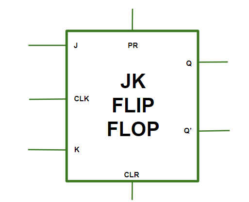
What is a flip flop?
A circuit that maintains a state until directed by input to change the state. A flip-flop is a component that is used to store one single bit of information.
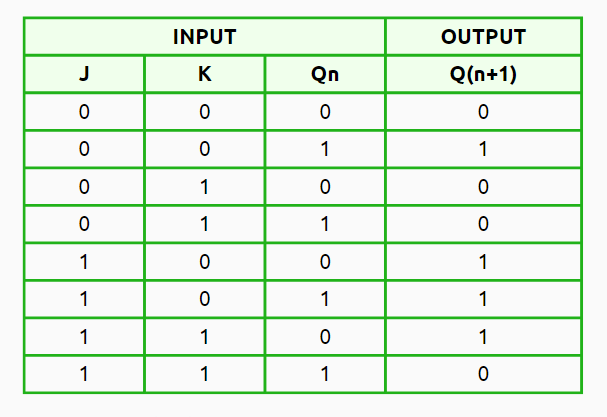
JK Flip Flop
Input Set (J) and Reset (K)
J | K | Q | Q+
0 | x | 0 | 0
1 | x | 0 | 1
x | 0 | 1 | 1
x | 1 | 1 | 0
J = 0, K = 0 (No Change): Here, the output Q(n+1) stays the same. This means the next state (Q(n+1)) is just like the current one (Qn).
J = 0, K = 1 (Reset State): In this case, the next state is reset to 0 (Q(n+1) = 0), no matter what the current state is (Qn).
J = 1, K = 0 (Set State): Now, the next state gets set to 1 (Q(n+1) = 1), again, no matter what’s happening in the current state (Qn).
J = 1, K = 1 (Toggle State): In this state, the output Q(n+1) toggles. So if the current state is set (Qn = 1), it will change to 0 (Q(n+1) = 0). If it’s reset (Qn = 0), then it flips to 1 (Q(n+1) = 1).
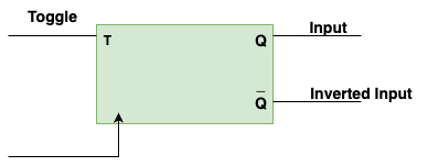
T Flip Flop
Toggle Flip Flop
It’s able to toggle its output depending upon the input
Toggle indicates that the bit will be flipped (0 to 1 or 1 to 0)
T | Q | Q+
0 | 0 | 0
1 | 0 | 1
0 | 1 | 1
1 | 1 | 0
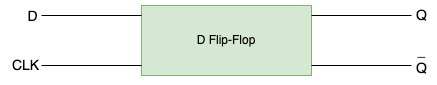
D Flip Flop
Delay flip flop or data flip flop
When clock input is high, the data is transferred to the output of the flip flop.
When the clock input is low, the output of the flip flop is held in its previous state.
D | Q | Q+
0 | 0 | 0
1 | 0 | 1
0 | 1 | 0
1 | 1 | 1
Q+ = D
What is the purpose of the clock signal?
Serves as a metronome for digital circuits
ensures that all components operate in sync
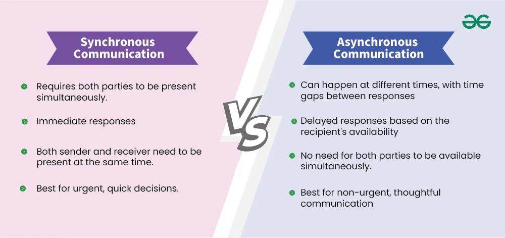
What is the difference between an asynchronous and synchronous component?
Synchronous communication requires the sender to wait for an immediate response, making it suitable for real-time interactions.
Synchronous = clock
Asynchronous communication, on the other hand, allows the sender to proceed without waiting, enabling better scalability and flexibility in distributed systems.
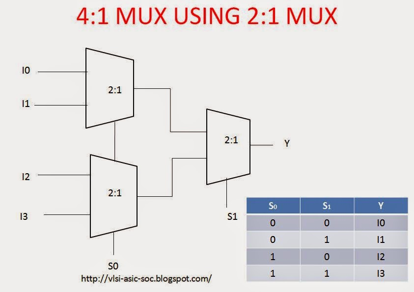
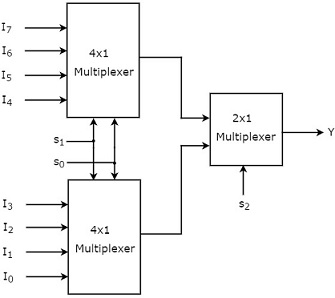
Multiplexers
Equation for a 2×1 multiplexer: Y = (D0 S’) + (D1 S)