Chapter 2 (Part 2) -Logic circuits & Number systems
1/22
There's no tags or description
Looks like no tags are added yet.
Name | Mastery | Learn | Test | Matching | Spaced |
|---|
No study sessions yet.
23 Terms
Rules for Combinational Circuit
Never combine two input wires.
A single input wire can be split partway and used as input for two separate gates.
An output wire can be used as input.
No output of a gate can eventually feed back into that gate.
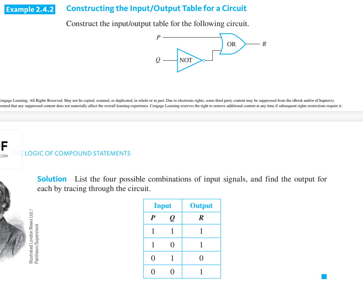
Constructing the Input/Output Table for a circuit
To construct the entire input/output table for a circuit, trace through the circuit to find the corresponding output signals for each possible combination of input signals.
Boolean variable & Boolean Expression Definitions
Any variable, such as a statement variable or an input signal, that can take one of only two values is called a Boolean variable. An expression composed of Boolean variables and the connectives and , or , ~ is called a Boolean expression.
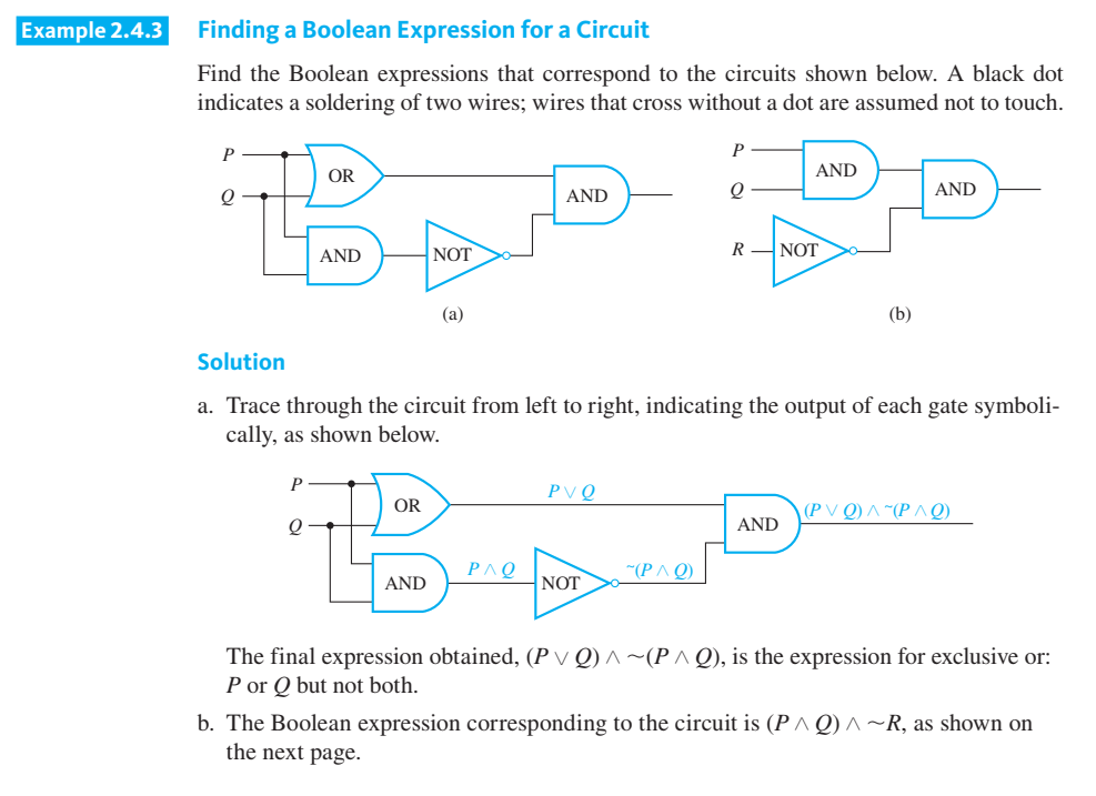
How to find a Boolean expression for a circuit
Trace through the circuit from left to right, indicating the output of each gate.
Combine all of those Boolean expressions into a single one
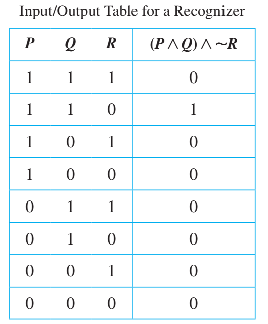
A recognizer
A recognizer is a circuit that outputs a 1 for exactly one particular combination of input signals and outputs 0’s for all other combinations.(in other words: the circuit only has 1 input in its table)
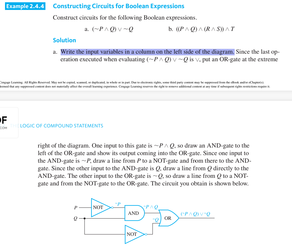
DCircuit Corresponding to a Boolean Expression
Write the input variables in a column on the left side of the diagram.
The logical connectives represent the gates.
Logical connectives always correspond to the order of the gates.
finding a Boolean expression corresponding to a given input/output table.
First construct a Boolean expression by identifying each row in the input/output table for which the output is 1.
For each such row, construct an and expression that produces a 1 (or true) for the exact combination of input values for that row and a 0 (or false) for all other combinations of input values.
(page 111-113)
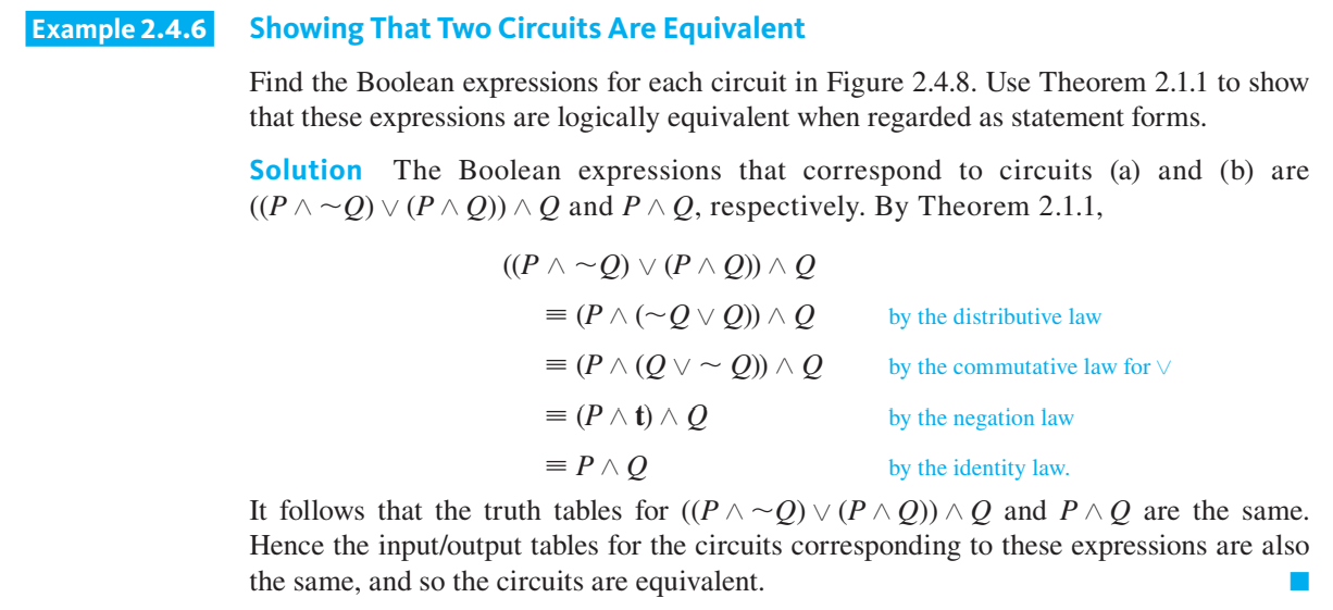
Digital logic circuits equivalency
Two digital logic circuits are equivalent if, and only if, their input/output tables are identical.
Note: Since logically equivalent statement forms have identical truth tables, you can deter-mine that two circuits are equivalent by finding the Boolean expressions corresponding to the circuits and showing that these expressions, regarded as statement forms, are logi-cally equivalent.
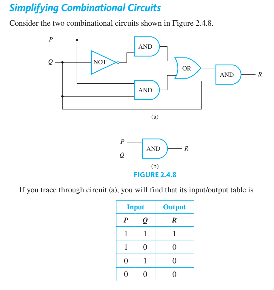
Simplifying a digital circuit
In general, you can simplify a combinational circuit by finding the corresponding Boolean expression, using the properties listed in Theorem 2.1.1 to find a Boolean expression that is shorter and logically equivalent to it (when both are regarded as statement forms), and constructing the circuit corresponding to this shorter Boolean expression.
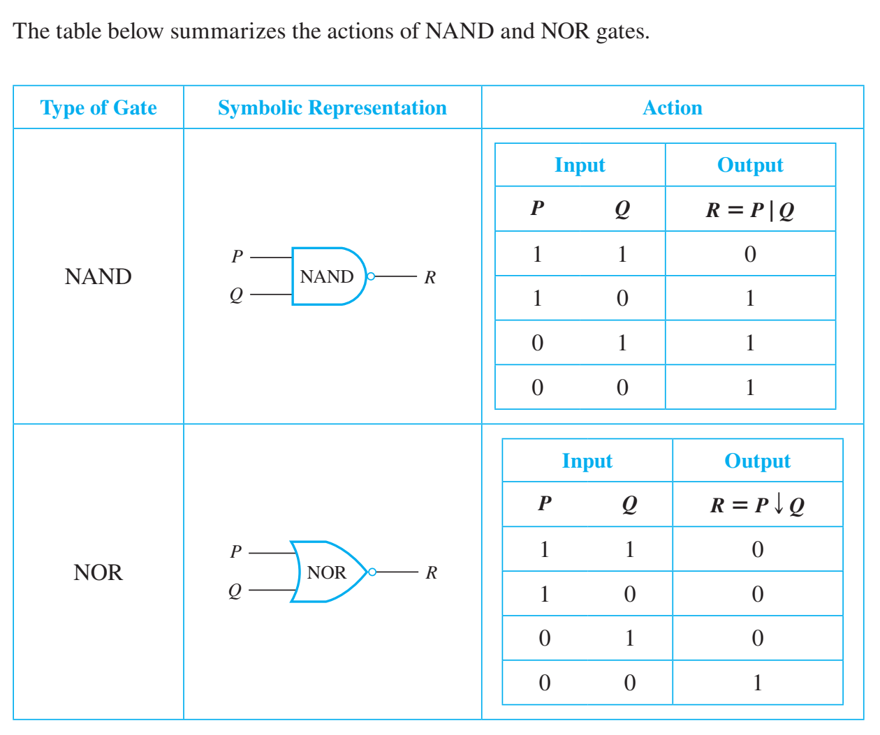
NAND and NOR Gates
The output signal of a NAND-gate is 0 when, and only when, both input signals are 1
The output signal for a NOR-gate is 1 when, and only when, both input signals are 0.
The logical symbols corresponding to these gates are: (| for NAND) called a Sheffer stroke. And (↓ for NOR) called a Peirce.
Binary notation
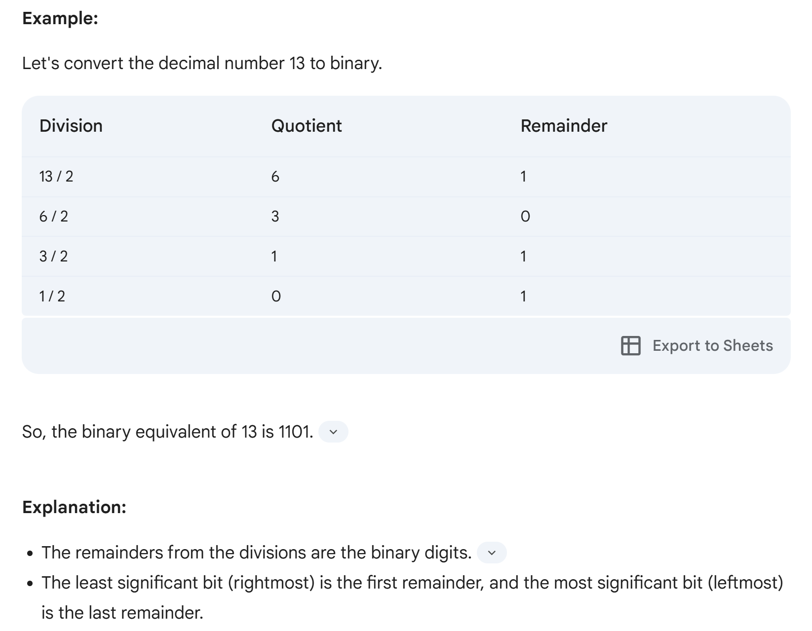
Binary notation is a number system that uses only two digits, 0 and 1, to represent numbers. To convert a decimal (base 10) integer to binary, we use a process called repeated division by 2.
Converting a Decimal to a Binary Number
Steps Involved:
Divide the decimal number by 2: Perform integer division and note the remainder.
Repeat: Divide the quotient obtained in step 1 by 2 again, noting the remainder.
Continue: Keep repeating this process until the quotient becomes 0.
Read Binary Number: The binary representation is the sequence of remainders read from bottom to top.
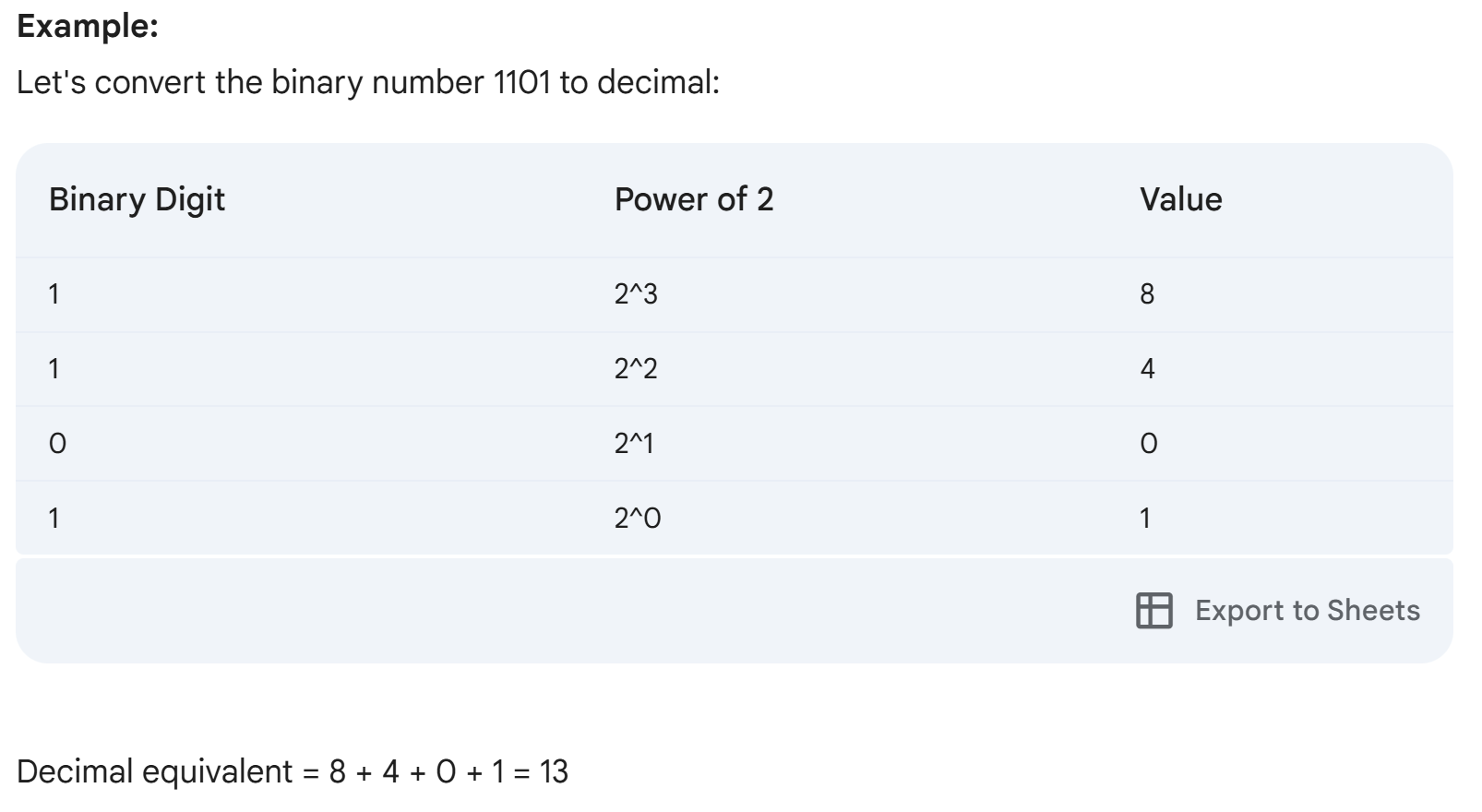
Converting a Binary to a Decimal Number
Steps Involved:
Assign Powers of 2: Write down the binary number and assign powers of 2 to each digit, starting from 0 on the rightmost digit and increasing by 1 for each subsequent digit to the left.
Multiply and Add: Multiply each binary digit by its corresponding power of 2.
Sum the Products: Add the results of the multiplications to get the decimal equivalent
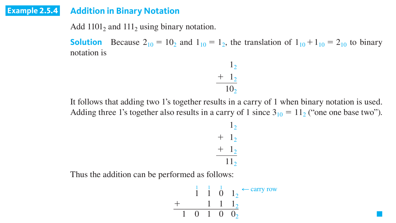
Addition in Binary Notation
Start from the rightmost digit.
Add the corresponding digits from both numbers.
If the sum is 2 (1 + 1), write down 0 and carry over 1 to the next column.
Continue this process for all digits, including the carry-over.
Subtraction in Binary Notation
Align the numbers: Place the larger number on top of the smaller one, ensuring digits in the same positions align.
Preform binary subtraction normally.
If the you encountered 0 - 1, borrow 1 from the next column, replace it with 0, and add two ones (1 and 1) to that 0 you’re solving for.
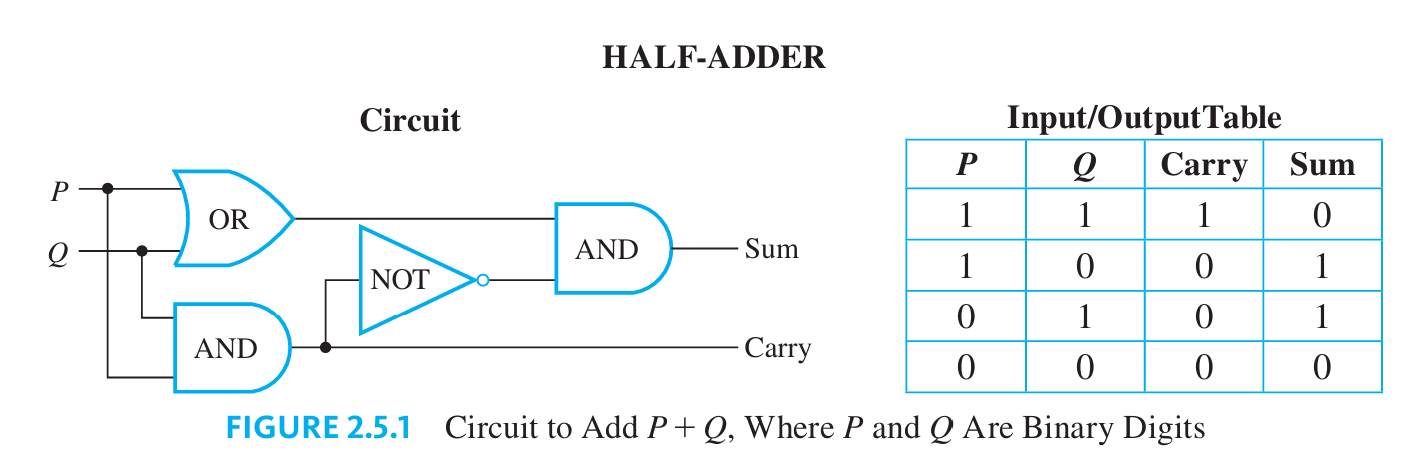
The carry, sum, and the Half-Adder circuit
Half-Adder Circuit: Understanding the half-adder circuit is fundamental in digital electronics and computer engineering because it forms the basis for building more complex arithmetic circuits.
Outputs:
Carry: 1 if both inputs (P and Q) are 1; created using an AND gate.
Sum: 1 if either P or Q is 1, but not both; created using an XOR gate.
Purpose: Adds two binary digits, producing a sum and a carry.
Circuit Name: Half-adder.
(121-123)
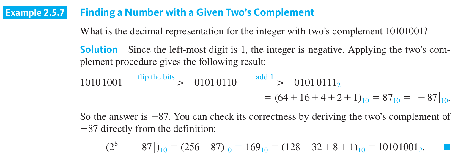
The 8-bit two’s complement
The 8-bit two's complement system is a method of representing signed integers in binary format. It allows for the representation of both positive and negative numbers within a limited range.
How it works:
Positive numbers:
The same as in the unsigned binary representation.
The leftmost bit (most significant bit or MSB) is always 0.
Negative numbers: The negation of a positive number is found by:
Inverting all the bits (1s become 0s and vice versa).
Adding 1 to the result.
The leftmost bit (MSB) of a negative number is always 1.
(123-125)
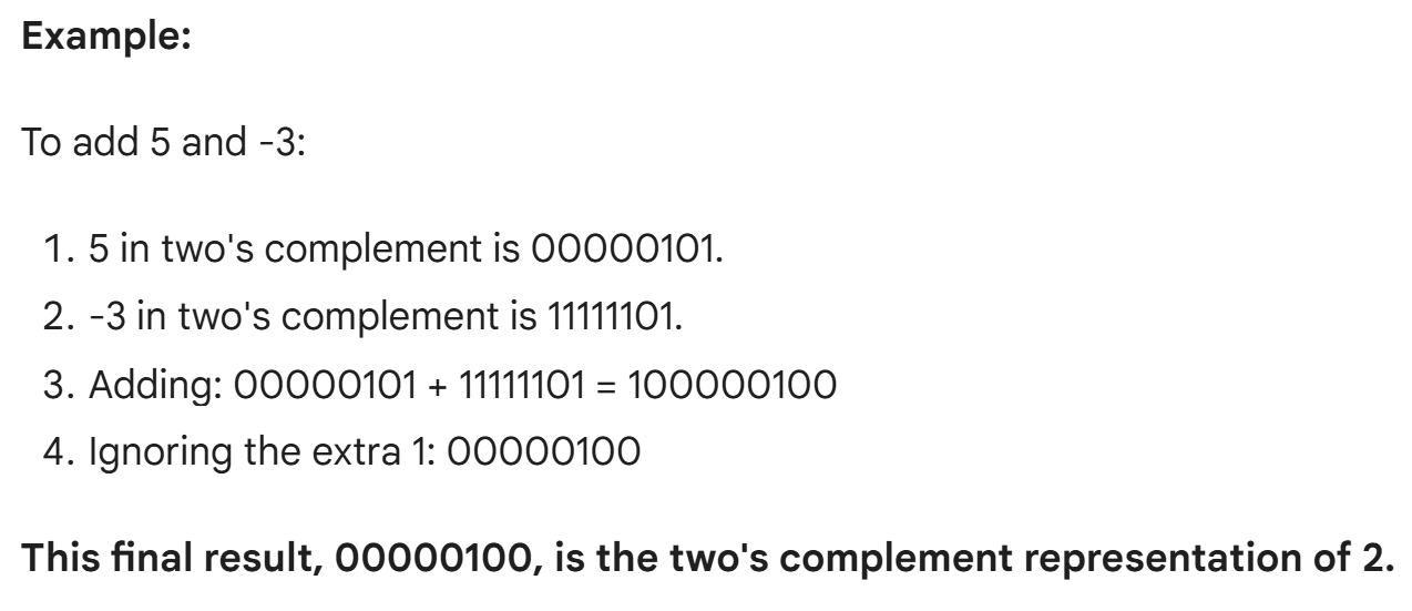
Addition and Subtraction with Integers in Two’s Complement Form
To add two integers in the range 2128 through 127 whose sum is also in the range 2128 through 127:
Convert both integers to 8-bit two's complement: This is a way to represent positive and negative numbers using 8 bits.
Add the numbers normally: Just add the binary numbers like you would add regular numbers.
Ignore any overflow: If the result is too big (more than 8 bits), just keep the last 8 bits.
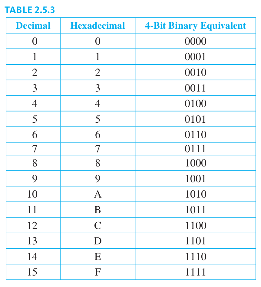
Hexadecimal Notation
hexadecimal notation is also called Base-16 notation. Hexadecimal notation is based on the fact that any integer can be uniquely expressed as a sum of numbers of the form:
d.16n, where each n is a nonnegative integer and each d is one of the integers from 0 to 15.
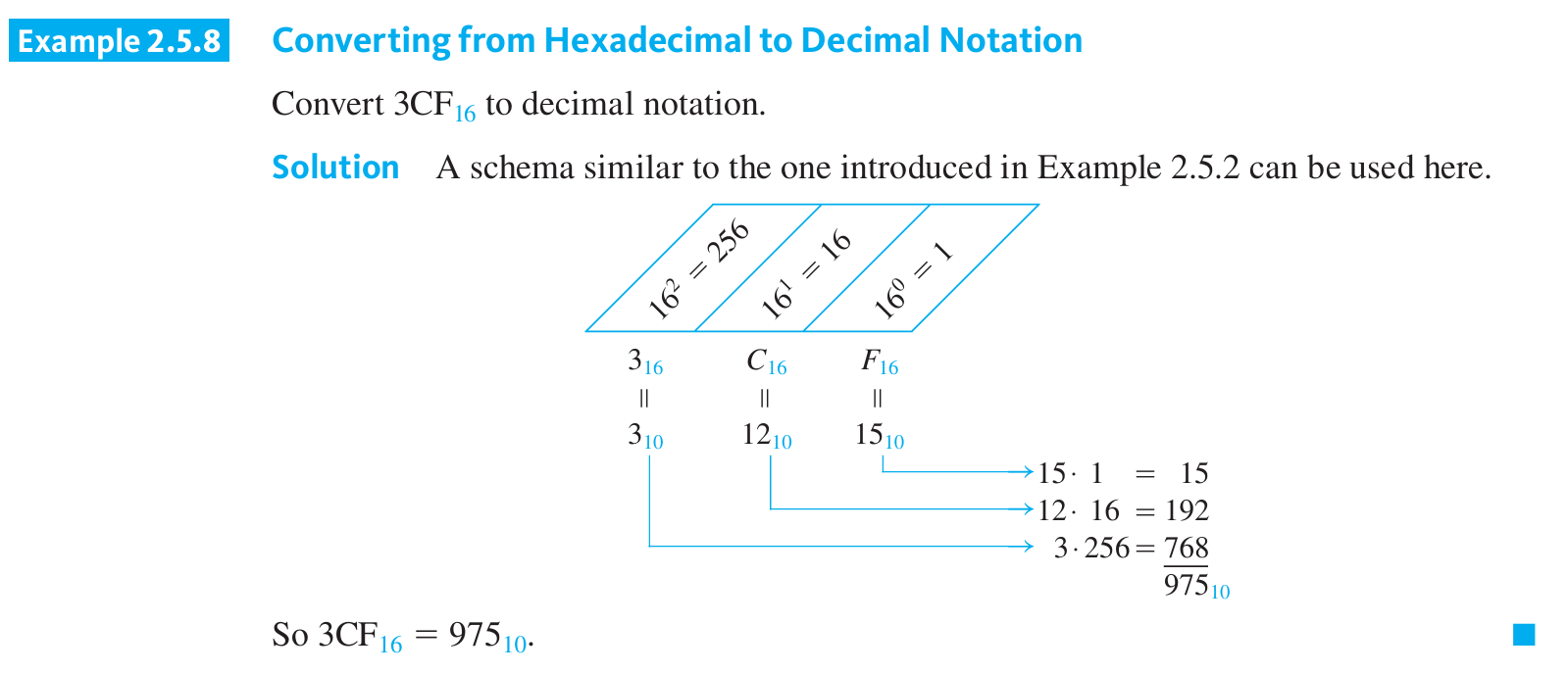
Converting from Hexadecimal to Decimal Notation
To convert a hexadecimal number to decimal, follow these steps:
Identify the place values: For each digit in the hexadecimal number, determine its place value. The rightmost digit is in the units place, the second from the right is in the 16s place, and so on.
Multiply each digit by its place value: Multiply each digit in the hexadecimal number by its corresponding place value.
Sum the products: Add up all the products calculated in step 2.
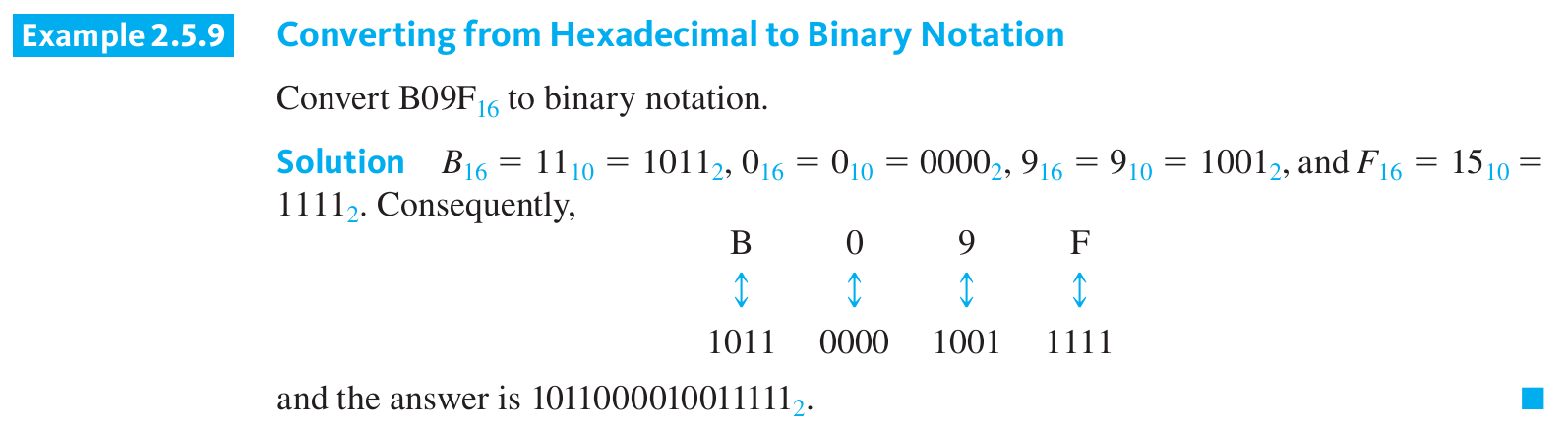
Converting from hexadecimal to binary notation.
1. Break Down the Hexadecimal Number: Divide the hexadecimal number into individual digits.
2. Convert Each Hexadecimal Digit to Binary: Use the Hexadecimal table to find the binary equivalent of each hexadecimal digit.
3. Combine the Binary Equivalents: Join the binary equivalents of each digit together.
(128-129)
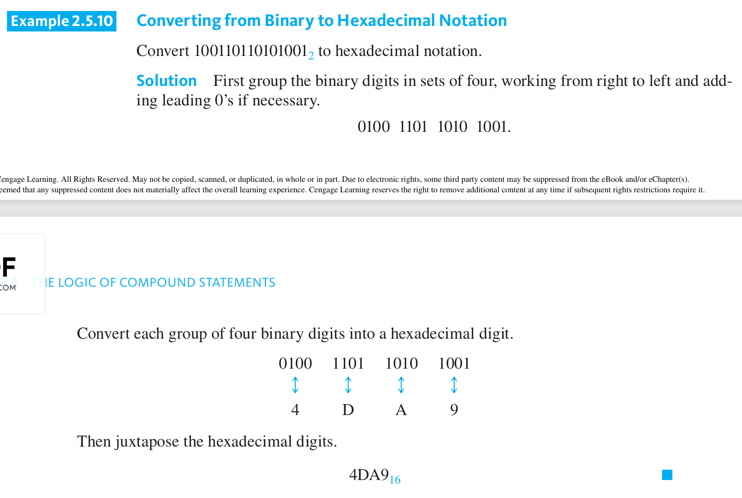
Converting from binary to Hexadecimal Notation
To convert an integer from binary to hexadecimal notation:
Group the digits of the binary number into sets of four, starting from the right and adding leading zeros as needed.
Convert the binary numbers in each set of four into hexadecimal digits. Juxtapose those hexadecimal digits.
Reading a Memory Dump
The smallest addressable memory unit on most computers is one byte, or eight bits. In some debugging operations a dump is made of memory contents; that is, the contents of each memory location are displayed or printed out in order.
To save space and make the output easier on the eye, the hexadecimal versions of the memory contents are given, rather than the binary versions.