Power electronics Weeks 1-4
1/75
There's no tags or description
Looks like no tags are added yet.
Name | Mastery | Learn | Test | Matching | Spaced | Call with Kai |
|---|
No analytics yet
Send a link to your students to track their progress
76 Terms
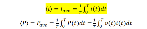
what is the formula for average current and averge power (integral one)
what is the formula for duty cycle
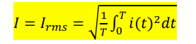
what is the integral formula for Irms
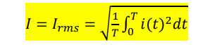
what is the integral formula for rms current if if part of the time period is 0
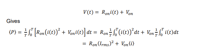
for a switch what can conduction loss be measured as
the voltage drop across the device and the the resistance or heat it dispitates
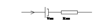
for this device calucalte the average power loss
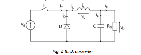
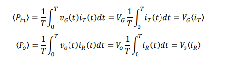
for this buck converter Vg and Vo are both constant calculate the averge power in and out
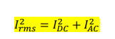
what is the equation for Irms not integral but relates ac and dc values
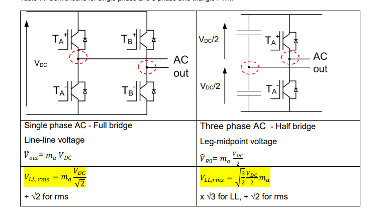
draw a h bridge with a single leg. Vdc/2 form and use igbt
add vsense and points a and o
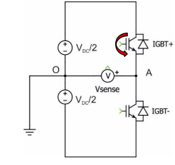
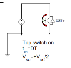
draw the equivalent circuit of a h bridge single leg when the top switch is on denote what the voltage is, and indicate current flow
use vdc/2 form and igbt
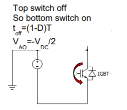
draw the equivalent circuit of a h bridge single leg when the bottom switch is on denote what the voltage is, and indicate current flow
use vdc/2 form and igbt
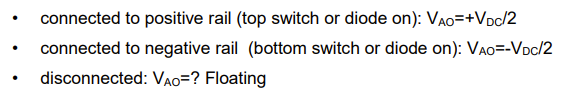
for a single leg on a h bridge what are the 3 possible voltages VAO can have
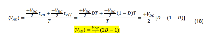
do the derivation for the average Vao of a single leg h bridge
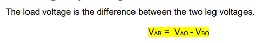
what is the realtionship between Vab and Vao
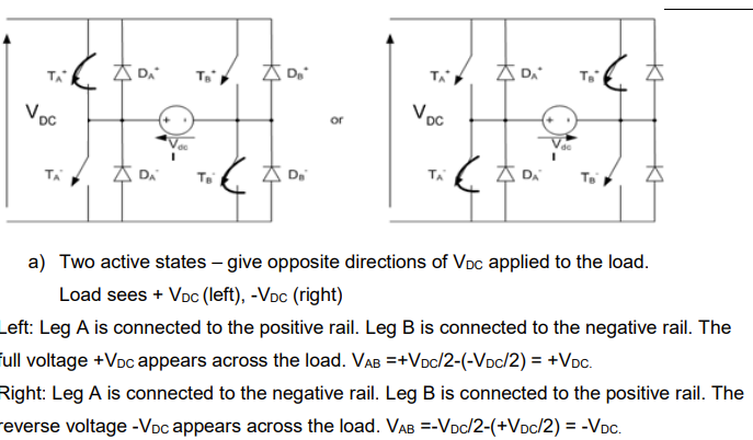
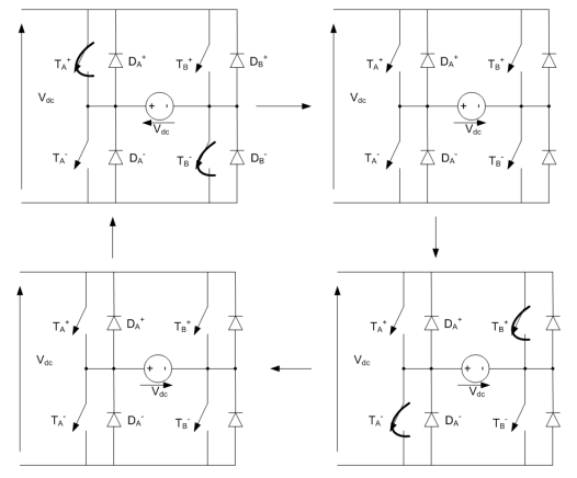
draw the two active states for a hbridge converter consisting of two legs. state what the load voltage vab is for these states using vab=va0-vbo
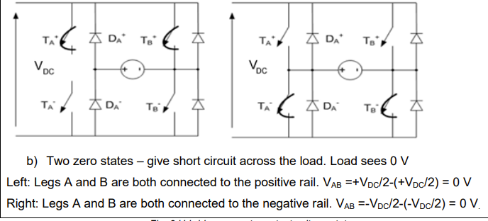
draw the two zero states for a hbridge converter consisting of two legs. state what the load voltage vab is for these states using vab=va0-vbo
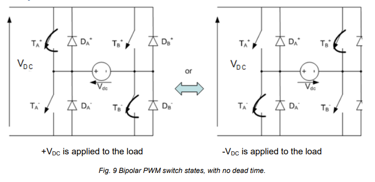
state what the bipolar PWM switch states are for a hbridge with two legs and no dead time
bipolar pwm alternates between +vdc and -vdc
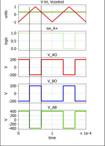
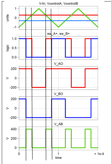
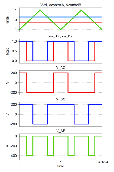
draw the switching grpahs for bipolar pwm and include switching rules
swicth A+ is active if vcontrol is greater than v triangle.
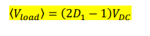
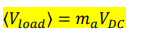
what is the equation for the avergae load voltage of bipolar pwm
where (2D-1)= the amplitude modulation factor or ma
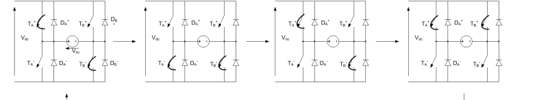
state what the bipolar PWM switch states are for a hbridge with two legs and dead time draw them.
alternates between two active switch states. and open circuit where all switches are open.
what is the benfit of dead time/blanking in bipolar pwm

draw the switch states for unipolar pwm for a positive load.
has 1 active state depending on if you want positive or negative load and two zero states.
draw the switching sequence diagrams drawing switch A and B on the same diagram and state switching rules. for unipolar pwm for posiitve load voltage
swa+ is high if vcontrol is greater than vtriangle.
for unipolar pwm what does the load voltage alternate between
+vdc and 0 or -vdc and 0. whereas bipolar goes between +vdc and -vdc
what is the equation for average load voltage in unipolar pwm
where ma now represents the DNZ.
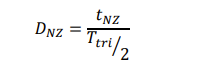
what is the eqaution used to caulate dnz in unipolar pwm
draw the switching sequence diagrams drawing switch A and B on the same diagram and state switching rules. for unipolar pwm for negative load voltage
state the differnce between bipolar and unipolar switching modes.
bipolar: switch comands to legs occur at same time, so switching events synchornised giving a big change in voltage across the load +-VDC and only two changes per triangle cycle. if D>0.5 then average load voltage is positive
unipolar: switch comands are staggered between A and B, voltage across load changes four ties per triangle cycle, and the change in voltage is lower as only one leg is changing at a time.
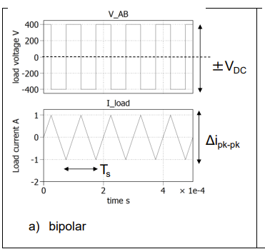
draw and label for bipolar the Vab load voltage graph and the load current graph beneath it , with a VAB of +-400V and Rof 10 ohms and ma =0
load voltage =ma * vdc
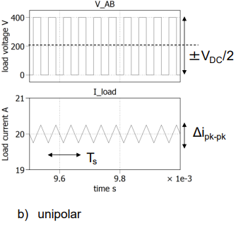
draw and label for unipolar the Vab load voltage graph and the load current graph beneath it , with a VAB of +-400V and Rof 10 ohms and ma=0.5
load voltage =ma * vdc
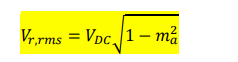
for bipolar pwm what is the Vr,rms equation and what ma causes maximum ripple
ma= 0
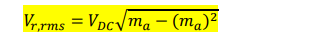
for unipolar pwm what is the Vr,rms equation and what ma causes maximum ripple
ma = 1/2
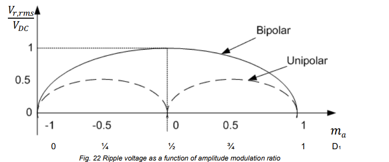
draw the voltage ripple graph vs ma for bipolar and unipolar.
grpah of ripple voltage vs amplitude moodulation
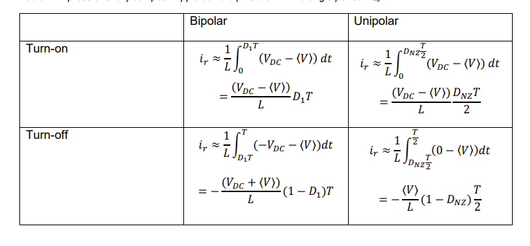
state eqautions table for turn on and turn off ripple current for bipolar and unipolar. dont worry about first line just the final eqautions
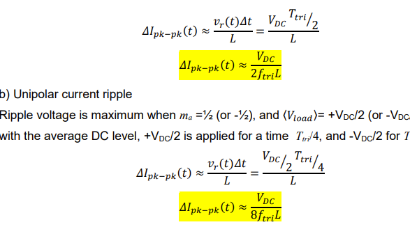
what are the two equations for maximum peak to peak ripple current in unipolar and bipolar
just look at yellow
what are negativities asccoiate with increased current ripple
increases overall rms current so increases copper loses and electrical noise.
if unipolar has less current ripple why would you use bipolar pwm
discontinous conduction is less likely, giving a linear voltage output.
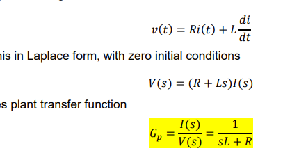
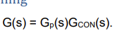
derive the plant transfer function for controller design
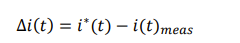
what is the realtionship between desired measured and error current
error can also be called difference
derive the transfer function for Gcon
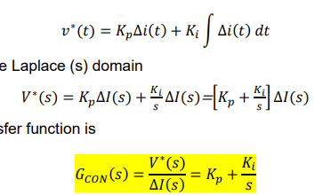
what is the relation ship between Ki and Kp and state other standard form for Gcon
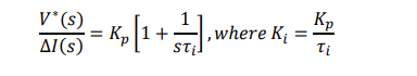
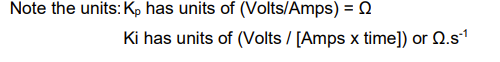
what is the units for Kp and Ki
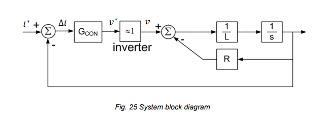
draw the syste block diagram for the plant contrller
what is the open loop transfer function/gain for the system
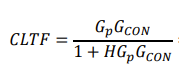
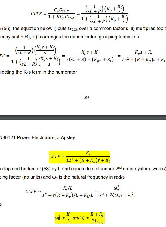
what is the eqaution for the cltf for the system
derive the cltf in quadratic form stating damping factor and wn bandwidth
when we ignore Kps in the numerator for the transfer function what is the differnce between the actual TF and the assumed one we use
actual repsonse is faster with overshoot copared to when we neglect kps in numerator
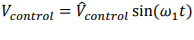
when converting Dc to AC what shape is the control voltage
a sin wave
In AC to dc what is the eqaution for V control copared to its peak and sin value
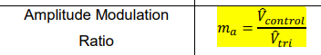
for converting DC to Ac what is the expression for the amplitude modulation ratio and what range do you want it to act
you want it to be between 0 and 1
for the freqeuncy modualtoin ratio for AC to DC what is the expression and what range do you want it to act
ideally greater than or equal to 21 odd and a multiple of 3
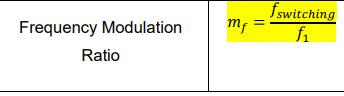
what is f switching and f1
f switching is the freqeuncy lf the refernce triangle wave and
f1= fundamental of the control sine wave and also fundaental of output voltage
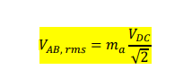
for AC to DC what is the Rms line voltage for single phase or VAB
what happens when ma exceeds 1 for Dc to Ac conversion
if this happens it means the peak of the sine wave exceeds the triangle wave, this causes overmodulation
and
there will no longer be a linear relationship between output voltage and ma
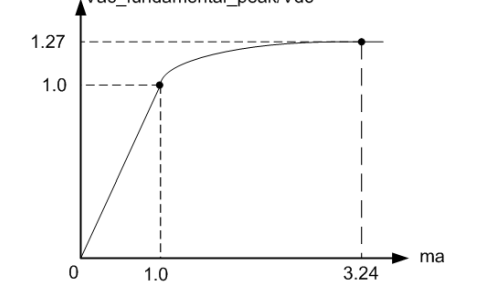
draw the graph which of ma vs the Vac fundamental/Vdc
reember the peak voltage of the load VAB can only max be 1.27*VDC
what is the eqaution which indicates half wave symetry
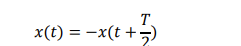
if half wave symterry occurs then what does this mean for the harmonics
waveform will only contain odd harmonics at 1,3,5 etcetra
if you reduce the frequency modulation ratio what does this do to the harmonics if fundmanetal is constant
as mf = f swithcing/ fundamental this means that fswitching decreases meaning all the harmoincs shift to the left along with there sidelobes but fundaental stays the same
if you reduce ma what does this do to the harmonic spectra
as ma= smaller and ma=control/triangle this means control voltage reduces meaning smaller fundamental
what is the difference in harmoincs for unipolar and bipolar
unipolar only see harmoincs around 2f and multiples of this
draw 3 phase ac to dc sinwave vs vtriangle
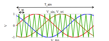
for single phase ac to dc state vpeak out and Vll,rms and for 3 phase state Vro peak and Vll,rms
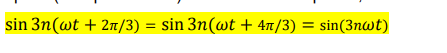
state equaiton which proves triplen harmoincs
because of this load voltage and line votlages do not see these triplen harmonics.
state two uses of triplen harmoincs
used to boost fundament voltage without overmodulation
use of mf as multiple of 3 to cancel switching harmoincs
what are the consequences of 3 phase dc to ac
do not connect star point to ground, high currents will result
star point voltages can cause interferance.
no effect on control phsae voltages are set at specific values
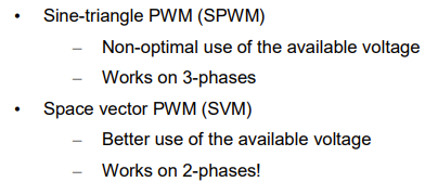
state the difference between sine-triangle pwm and space vector Pwm
what is the switching rule for space vector modualtion
only one switch can be on(top or bottom per leg)
for leg votlages what are the voltages generally if both switches are on and off
if both on: short circuited
both of: open circuit floating voltage
how do you create your desired voltage using space vectors
take the vector sum of your a ,b c phase voltages
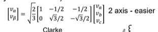
what is clarkes transfomration for convertting from Va,Vb,Vc to hust Valpha and Vbeta. 3 phase to two phase conversion
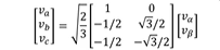
what is the inverse clark defintion
note the matrix conversion compared to the no ninverse the only difference is the matrix is transposed
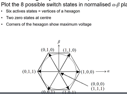
draw the hexagon alpha beta plane showing all 8 states
normalisation come back to this no clue
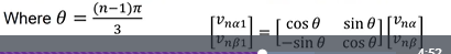
for space vector modulation if you are not in the first vector what are the formula to calculate theta and the matrix conversion to get the first sector.
for space vector modulation when choosing which zero state you use(1,1,1) or (0,0,0) what do you pick and why
you chose the zero state which minimises the number of switch transtions to minimise switching losses
for space vector modulation what is the switching freqeuncy and sampling freqeuncy
sampling frequency = 1/T = two active states and 1 zero
switching freqeuncy= 1/2T = four active states and 2 zeros