General/PE Handbook
1/63
There's no tags or description
Looks like no tags are added yet.
Name | Mastery | Learn | Test | Matching | Spaced | Call with Kai | Chat |
|---|
No analytics yet
Send a link to your students to track their progress
64 Terms
fb (Bending Stress) for typical beam
fb = M/S
NDS 3.3
Applied moment for simply supported beam with uniformly distributed load
M = wl²/8
Handbook 4.1.7
Elastic Section modulus (Sx) for typical beam
S = I/c
c = distance from beam N.A. to outermost tension or compression fiber
bd²/6 for simple rectangular cross-sections where c is the same whether looking at the compression or tension fiber
NDS 3.3 or handbook
The elastic section modulus is for serviceability design of non-compact members, used to control deflections, so it’s more conservative/safe than the plastic section modulus
Opposite of plastic section modulus which designs for full yielding of entire member cross-section, so this is riskier and allows for more deflection in the member. Gets very close to rupture
fv (shear stress) for typical beam
fv = VQ/Ib = 3V/2bd
This is just the shear flow divided by the breadth/thickness of the beam
b is net cross-sectional width (if hollow then it’s the width excluding the hole width)
NDS 3.4.2
ASD Design
Uses adjustment factors to decrease nominal strength to design strength
Won’t be used to factor the applied loads
Used for wood and masonry design
Can be used for steel and concrete, HAVE TO FACTOR STRENGTH IF ASKS FOR ALLOWABLE
Most commonly will be dividing strength by 2.0 for steel
LRFD Design
Uses strength reduction factors to decrease nominal strength to design strength AND uses load combinations to increase service loads to ultimate loads, noting that the ultimate loads are also known as the required strength
If the question asks to factor the applied load then I should definitely use LRFD because ASD doesn’t factor applied loads
Used for concrete, steel and bridge design
Nominal strength
Calculated strength of a material before being reduced/factored
Letter with subscript n for LRFD
Letter without apostrophe for ASD
Design strength
Reduced/factored strength of a material using strength reduction/adjustment factors
Phi next to letter with subscript n for LRFD
Letter with apostrophe for ASD
Strength Reduction and Adjustment Factors
Factors provided in each codebook to decrease calculated material capacities for factors of safety, used for both ASD and LRFD design
Service Load
The nominal or unfactored calculated applied load on a member
Ultimate Load
The increased/factored applied load on a member
Letter with subscript u for LRFD
Letter with apostrophe for ASD
Load combinations
A series of load factors found in each codebook that are dependent on loading conditions
Resultant Force for multiple PLs on a beam
Rf = sum of all forces in a direction
xR, use sum of moments with only resultant applied force and support reaction forces to find xR
Process to find maximum moment for multiple moving unequal concentrated loads across simply supported beam
First find support reaction forces through sum of moments
Determine the applied resultant force by adding up all the applied forces
Determine the resultant location along the beam through a sum of moments with only the resultant force on the beam and one of the calculated reactions
Then using maximum moment principle from Handbook 4.1.2 align the resultant and the greatest/middle concentrated load to be equidistant from the beam’s centerline. Choose the load and the side of the load based on what would create the maximum moment. May need to check multiple scenarios
Redo the support reaction force calculations
Then find the moment at the location of the larger applied load close to the centerline by taking a cut/section through the beam at that location and solving
To take a section cut, it’s the same process as solving a truss problem with method of sections. You just take a cut wherever and the only consider the forces on one side of the beam.
Table with presumptive bearing capacities by soil type
IBC Chapter 18 - Soils and Foundations, 1806 has presumptive values
Abutment
The retaining wall/foundation wall at the ends of a bridge
Culvert
A tunnel that goes below a road/driveway that’s intended for stormwater drainage
Material unit weights
ASCE 7 Commentary C3
AASHTO Table 3.5.1-1 (extremely general)
Ashlar stone
Opposite of rubble stone, this will be very finely cut rectangular stone
Beam under torsion
Torsion is like wringing a towel out, or rotation along the length of the beam
Torsion causes shear stresses in the beam
Circular beams are the strongest against torsion
Torsional Stress Tau (T) = Torque (T) * r / J (Polar moment of inertia)
So the torsional stress increases as the radius/beam size increases
And torsional stress decreases as polar moment of inertia increases
These occurrences are because like a moment arm, the mass far from the object’s centroid will be much more efficient at resisting torsional stress than mass near the object’s centroid
Polar Moment of Inertia
Measure of objects resistance to torsion/twisting, like a shaft being turned
This is literally just the sum of Ix and Iy, or (2) axes of moments of inertia
J = r² * A
r = radius of gyration
Radius of Gyration
Radius of an area from a point where that area highly affects the moment of inertia
rx = sqrt(Ix/A)
Moment of Inertia
Ix = A*d² = Integral (x²)dA
For rectangle, Ix = bd³/12
An object’s resistance to rotation based on its mass
Ix is resistance in rotating about the x axis (deflecting for a beam)
Iy is resistance in rotating about the y axis (buckling for a column)
For a hollow member, Itotal = Iout - Iin
The x² accounts for the fact that mass further from the centroid has a much higher resistance to rotation than the mass near the centroid
dA is a tiny slice of the overall area
Moment of inertia has distance units to the 4th power
Also known as second moment of area…
Shear Diagram
Should step vertically at concentrated loads, slope linearly at UDL, and slope parabolically at triangular distributed loads.
Reaction values for simply supported beams under PL and UDL are the same, but their load distribution is different
Mmax is typically where the V diagram crosses the x-axis and the shear is zero
Can do similar triangles with (2) different sections of a shear diagram when UDL. Use V diagram distance and shear values to determine location of maximum moment
V will have values at start and end of diagram
Unaffected by hinges or internal moment couples
To find the shear at the hinge just take a section cut and consider the left or right side of the beam
Note that each hinge separates the beam into individual free body diagrams
V should jump to opposite side of V diagram at all supports
Capital W = total load on beam, while lowercase w = distributed load per unit length
Moment Diagram
Should slope linearly where V diagram steps rectangularly, slope parabolically where V diagram slopes linearly, and slope cubically where V diagram slopes parabolically
Accordingly, the Mmax for a PL is greater than that of a UDL because the UDL is distributed across the length as shown in the triangular V diagram
Change in section of M diagram = area under section of V diagram
M will be zero at any hinges
Accordingly, we can do sum of moments at the hinge and only consider the left or right sides of the beam
M will start and end at zero except for at fixed supports where it should have a value
Max M is where V = 0 and crosses x-axis
Should be similar to a deflection diagram in that Moment should be negative for extreme sagging/deflection like at concentrated loads or UDL, and Moment should be positive for hogging/upwards bending
An isolated CCW moment at the midspan causes a jump in the M diagram since it would be picking up the right side of the beam/relieving the right side from tension (as represented by the bottom side of the M diagram)
Negative Moment Zone
In beams, typically over intermediate supports and in cantilever beams, where the top edge turns into tension (hogging) and the bottom turns into compression.
Unit weight of water
62.4pcf
Effective soil stress at a certain point
Effective stress = Total stress - pore water pressure
Total stress is sum of soil layer unit weights multiplied by the height of each soil layer above the point in question
Pore water pressure is just water unit weight 62.4pcf multiplied by height of water layer about point in question
Diaphragms
Floor and roof systems act as deep beams for lateral line loads, so the moment within a diaphragm M = wl²/8
The structure perimeters that are along the length of the line load are the chords, whose force can be found from taking a cut through the deep beam and using the T/C moment couple along with the beam depth to find the Fc/Ft = M/d
The structure perimeters that are on the edges of the line load are the struts, whose force can be found from a simply supported beam with a UDL, F = wl/2
Extra - Next step in lateral force transfer would be dividing strut reactions by wall length to get unit shear
Zero force members in trusses
All non-collinear members at 2-member and 3-member joints where no external loads are applied
Then do sum of forces in x and y to check for other zero force members
First moment of area
Q = A*ybar
Cross sectional area of the outer member of a composite/built-up member multiplied by ybar (the distance b/t center of entire cross section to center of outer member)
Shear flow
q = VQ/I
Q = first moment of area, see flashcard
Horizontal distribution of shear force per unit length over a composite/built up cross-section like I-beams used to determine fastener spacing for nails/bolts to prevent the different composite section components from sliding apart
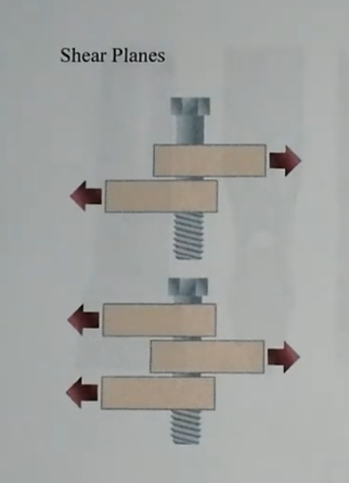
Shear plane
Failure location for a bolt connecting steel plates
For several steel plates, the force on the bolt cross section where it will fail will be reduced by the number of steel plates and the increased number of shear planes
Stress and strain, principal stresses
PE Handbook 1.6.4, Mohr’s circle
Equation for principal stress
Note that tensile stresses are positive and compressive stresses are negative
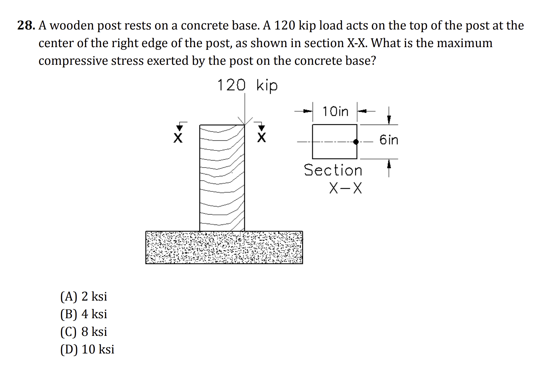
Eccentricity
e = distance from center = M/P = Moment divided by the load
To calculate eccentric stresses, find the moment induced by the eccentricity (M = F*e), and then the eccentric bending stress induced by the moment (fb = M/S)
For the max compressive stress exerted onto a support (typically the foundation), the eccentric bending stress should be added to the normal compressive stress (fc = F/A), just the applied load divided by the area of the transfer member (usually a post or column)
IBC Deflection Limits
Chapter 16 - Structural Design, 1604 - General requirements, 1604.3 - Serviceability
For deflection limits, you get out whatever unit you put into it. Put span in inches then you get allowable deflection in inches, and vice versa with feet
Stress
Force divided by an Area
Strain
epsilon = change in length divided by the original length
Unitless
Strain has a direct relationship with ductility
Modulus of Elasticity
E = stress divided by strain
So E = (F/A) / (change in L/original L)
Elastic longitudinal deformation
Delta = PL/AE or play
Relative Density (Dr)
Dr is a percentage of how dense/compact the actually soil is relative to the specific max/min values possible for that soil
Dr = emax-e / emax-emin
Can also use this eqn to solve for e = emax - Dr*(emax-emin)
The void ratio e will be max at Dr = 0% and min at Dr = 100%
Multiple graphs in Handbook to determine or huge equation in transpo section, but table with associated N60 values is the quickest
Note that transpo section does have some helpful Geotech stuff
Note that the effective overburden pressure is the same as the effective stress we find with the total/pore water stresses
Linear Interpolation
Set slope of 4 known points equal to slope of 3 known points, then solve for the unknown point
(y2-y1) / (x2-x1) = (y-y1) / (x-x1)
Where blank x and y values are the new data set we’re searching for
Just multiply the left side by (x-x1) and add y1 to solve for y, or solve for x
Process to find total lateral earth force per unit length for various retained soils acting on a cantilevered retaining wall
Multiply unit weights (dry soil, saturated soil, water, etc.) by Ka (coefficient of active pressure) to get triangular pressures
Then multiply by areas to get force per unit length, noting that the soil above the water table will have a triangular pressure above the water table and a rectangular pressure below the water table
Alternatively you can just find the average soil unit weight (unit weight 1 x height 1 + unit weight 2 x height 2) / total wall height
Then use F = .65 * ka * avg unit weight * (total wall height)²
Submerged Soil Density
This is the density of the soil itself that is under water
Gamma prime (submerged density) = Gamma saturated - Gamma water
Lateral earth pressure facts
k coefficients are a ratio of the horizontal stresses divided by the vertical stresses exerted by the soil
The strain required to achieve passive pressure is much larger than the stress required to achieve active pressure
Active pressure is the backfill soil pushing the wall over (0.2<ka<0.4)
Passive pressure is the wall sliding into the soil opposite the backfill and compressing the soil (3<kp<10+)
At rest pressure, used to design for rigid retaining/foundation walls like basements or bridge abutments (0.4<k0<0.6)
Active earth pressure can be negative, typically in cohesive soil where the soil is expanding away from the wall causing soil tension cracks
For surcharge, use Handbook and Ctrl+F “surcharge” to get to a table with the different types of surcharge loading conditions and associated equations. Most typical will be uniform surcharge where horizontal pressure over the wall height = the surcharge uniform line load value * ka. Then to get horizontal force at lower 1/3 of wall height just multiply that new horizontal pressure value by the wall height
What type of soil unit weight is the bearing capacity based on when the water table is at surface level?
Buoyant/Effective weight, which is similar to the effective stress where you just subtract the water weight from the soil weight
Process to determine factor of safety for gravity retaining wall against overturning at toe
Divide capacity moment from retaining wall weight by the demand moment from soil weight
Capacity moment is weight of retaining wall (more accurate to break into sections) multiplied by lever arm from toe
Demand moment is active force at 1/3 the wall height (Pa) from handbook equations/diagrams multiplied by lever arm from toe
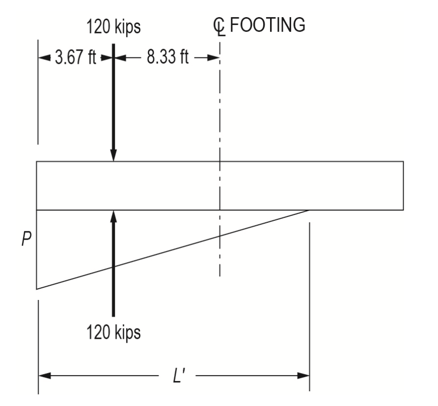
Soil bearing pressure under rectangular footing with braced frame above experiencing overturning (one compression PL at one end and one uplift PL at other end)
Find resultant of all vertical forces and sum of moments about the centerline
The eccentricity distance (offset of resultant force from centerline) will be equal to the resultant Moment divided by the resultant Force
Run a check to see if eccentric force is within kern (middle 1/6 of footing) where there would be no uplift and entire footing would be engaged
Find length of soil’s triangular normal pressure on footing by (entire footing length / 2 - eccentricity distance) * 3
By 3 because soil will replicate applied load, with applied PL acting at 1/3 the length of the triangular pressure from the footing edge
Find the value of the triangular line load by equating the applied PL = triangular area = 1/2*base*height
Base = pressure’s length
Height = value (k/ft) of triangular line load
Finally find the effective soil normal pressure by dividing the line load by the remaining footing width
How to determine forces in cables with multiple point loads and provided deflection at a point
Can do sum of moments to determine vertical reactions at supports, then trig to determine horizontal reactions at supports
General Cable Theorem = The horizontal component of the cable tension is constant throughout, and M at any location = Fx * vertical displacement at that location
Reminder that a² + b² = c² is true even for load values, so you can find the axial force in a cable if you have the x and y forces at an adjacent support
How to check bearing for cantilevered retaining wall
Actual/Demand bearing pressure is from Handbook 3.4.2.2 (because the footing is eccentrically loaded), equation for qmax is based on if eccentricity from the Moment about the footing centerline / total weight on the footing (from soil, wall, etc.) is in the kern (center 1/6) of the footing or not
Capacity/Required/Allowable bearing pressure is from IBC 1806.2 based on soil type
How to check sliding for cantilevered retaining wall
Capacity/Required/Allowable is multiplying the coefficient of friction from IBC Table 1806.2 by the total weight acting on the footing (soil, wall, etc.)
1807.2.3 says that the Factor of Safety (capacity/demand) must be 1.5 or greater
Actual/Demand is subtracting the lateral active pressure force by the lateral passive pressure force
Lateral active pressure should just be ka*soil unit weight*wall height²/2
Alternatively for capacity, can use factor of safety against sliding equation from handbook 3.1.3 which uses a friction angle and cohesion
Note that Pv for this equation would be the vertical component of the active pressure if the backfill soil were inclined
How to check overturning for cantilevered retaining wall
Do a sum of the moments about the footing toe corner where it would overturn/hinge for the demands (active pressure and sometimes passive pressure depending on if there’s a key or not) and a separate one for the capacities (all other forces like wall weight, soil weight, and passive pressure if no key)
Then per IBC 1807.2.3 check if capacity/demand FOS ratio is 1.5 or greater
How to determine axial stress in pinned steel beam from a given temperature change
Use handbook equation for deformation from temp change
Use stress = strain * Modulus of elasticity
How to find unbalanced portion of fixed-end moments in a loaded beam
Use equations in handbook 4.1.6, basically you pretend that the proposed joint is fixed and use the handbook’s equations to calculate the moment from the loads on the beams directly on each side of the joint only
Then to find the unbalanced portion you simply take the difference between those moments
This is one step in the Hardy Cross method towards analyzing statically indeterminate beams
How to determine tensile force in the top of (2) lag screws (2 rows of screws) fastening a wood ledger board to a wall, provided the download of a joist bearing on a metal hanger fastened to the ledger board and provided the resultant compression location (which is near the bottom edge of the ledger board)?
Get the moment M at the wall from the joist download (F1*d1, where d is thickness of ledger board)
That moment M should be equal to the moment M from the tensile/resisting force in the top lag screw, so do F2 = M / e2 where F2 = lag tension and e2 equals distance between resultant compression location to the top lag screw
How to find the vertical settlement of a spread footing due to a lateral point load applied to a series of connected beams/columns offset vertically and horizontally from the footing, provided the soil vertical modulus of subgrade aka coefficient of subgrade reaction (k) and a diagram showing only 2 footings in plane with the lateral load?
Ctrl+F “modulus of subgrade” in the handbook, to get the equation k = P/delta, rearrange for delta which is the deflection/settlement
To find the pressure exerted on the soil from the compressive force on the footing from the applied lateral load:
Find the moment from the lateral load at the footing in question
Then do a sum of moments about the other footing that would be experiencing uplift using the applied lateral force and the reaction force at the compressed footing, solving for the footing reaction force
Pressure = F/A, compressive force and footing area
How to determine the ultimate allowable bearing capacity for a concentrically loaded strip footing with the water table halfway up the soil over top?
Use the concentrically loaded strip footing equation qz from the handbook Chapter 3 Geotechnical, 3.4 Bearing Capacity, 3.4.2
Note that with the water table above the strip footing there’s a correction factor table for the N values, directly below the N values table. You should use this to reduce the N values and still use just the soil unit weight for the surcharge on the footing, instead of calculating the effective soil stress considering the pore water pressure
Some questions may ask for the NET bearing capacity instead of the ultimate, the net bearing capacity would be the ultimate minus the weight of the soil over the footing (gamma * Df). This basically trims down our bearing capacity value to be more specific about exactly how much load can be applied to the foundation
Then, to find allowable bearing capacity, just divide by the FOS
What is negative skin friction in piles and when does it occur?
Negative skin friction is the downward drag on piles due to consolidation in the surrounding soils
How to find max factored flexural demand on the stem wall of a cantilevered retaining wall?
Find the resultant active pressure force from the typical ka*soil unit weight*(z)²/2 equation from the handbook, remember that z is the height of just the stem wall and doesn’t include the footing height
Multiply that active pressure force by the lever arm/distance between the top of the footing and the force
Using ACI 5.3.8 or something factor the applied load by 1.6 to get final answer
How to find the maximum moment and shear induced in the header/beam that’s part of a 2-column, 1-beam moment frame with a lateral point load applied at the top of the moment frame?
The maximum moment in the beam occurs at the connections to the columns, and is equal to the moment in the column top ends because it is transferring 100% of that moment for the columns. That moment can be calculated by multiplying the shear force in the columns by the upper portion of the column above the inflection point where the column moment = 0.
The shear force at the column bases and all throughout the columns is just the lateral point load divided by 2
The column inflection point for a fixed base moment frame is theoretically right at the mid-height, but in reality it’s about .55*H
The beam shear force can be found by doing a sum of moments at either end of the beam. The setup is a beam fixed at both ends with concentrated end moments acting in the same direction (clockwise). The end supports will have equal and opposite vertical reactions. Taking a sum of moments at one end gives M1 + M2 - R2*L, so R2 = (M1 + M2) / L
How to find the optimum length of a combined footing supporting 2 columns with vertical downloads, provided their forces and locations from the left side of the footing?
Just do a sum of moments from the left end of the footing with the 2 column downloads and a single upward vertical reaction force at L/2, solving for L
What is the optimum longitudinal reinforcement layout for a cantilevered retaining wall to resist the lateral earth force?
The rebar in the stem should be as close to the backfill side of the wall as possible
The rebar in the toe (away from the backfill) should be on the bottom of the footing, since when the wall overturns the toe will be bent downward with tension at the bottom
The rebar in the heel (backfill side) should be on the top of the footing, since when the wall overturns the heel will be bent upward with tension at the top
How to find required diameter of a concrete caisson driven a depth into the ground, provided the caisson thrust force, uplift force, allowable end bearing capacity stress, and allowable skin friction stress?
Set the uplift force = allowable skin friction stress * surface area (height x circumference of (2 x pi x r)), and solve for the diameter
Then check with the newfound diameter that the thrust from the machinery pushing the caisson into the ground < uplift force + end bearing force
Calculate the end bearing force = allowable bearing capacity * caisson bottom area
What is the distribution factor for a specific column or beam in a joint of a moment frame?
Pulling from the AISC effective length factor section of Appendix 7, this is equal to G = E*I/L for the individual column or beam divided by the sum(E*I/L) for all other columns/beams at that joint