DC to DC - Converters
1/21
Earn XP
Description and Tags
Name | Mastery | Learn | Test | Matching | Spaced | Call with Kai |
|---|
No analytics yet
Send a link to your students to track their progress
22 Terms
What is the function of a DC-DC converter?
Efficiently change a DC voltage level to another DC level using switching and energy storage elements.
Name four common DC-DC converter types.
Buck, Boost, Buck-Boost, and Cuk.
Common switching devices?
MOSFETs or IGBTs because they can switch at high frequencies.
Can SCRs be used in DC-DC converters?
Generally no, because they cannot be turned off by gate control and switch too slowly.
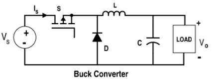
Principle of a Buck converter?
Steps down voltage; average Vout is lower than Vin based on duty cycle.
Voltage relation for Buck?
V_{out}=D*V_{in}
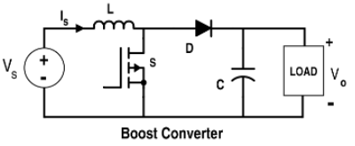
Principle of a Boost converter?
Steps up voltage; stores energy in inductor during ON, releases to load during OFF.
Voltage relation for Boost?
V_{out}=\frac{V_{in}}{\left(1-D\right)} , where D=\frac{T_{on}}{T_{on}+T_{\circ ff}}
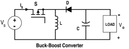
Principle of a Buck-Boost converter?
Inverts polarity and can step up or down depending on duty cycle.
Voltage relation for Buck-Boost?
V_{out}=-V_{S}*\frac{D}{\left(1-D\right)} , , where D=\frac{T_{on}}{T_{on}+T_{\circ ff}}
What determines CCM vs DCM?
CCM: I_{L} never falls to zero during a switching cycle.
DCM: I_L drops to zero before the next cycle starts.
Compare I_{load} and L — lighter load or smaller L pushes operation into DCM.
Typical switching frequency range?
About 20 kHz to several hundred kHz.
Why are DC to DC Converters more efficient than linear regulators?
Linear regulators control voltage by dissipating excess energy as heat through a continuously variable element (like a transistor in its active region).
DC–DC converters, on the other hand, regulate voltage by rapidly switching on and off, storing and transferring energy through inductors and capacitors — this minimizes power loss and makes them far more efficient.
Applications of DC-DC converters?
Power supplies, battery systems, renewable interfaces.

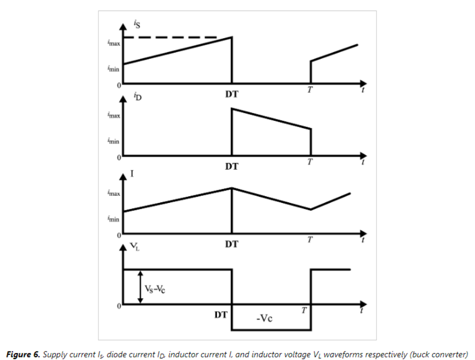
Describe Buck voltage/current waveform.
Buck Converter Waveforms
I_S = supply current – flows during switch ON, decreases when switch OFF
I_D = diode current – zero when switch ON, conducts when switch OFF to maintain inductor current
I_L = inductor current – increases when switch ON, decreases when switch OFF (continuous in steady state)
V_L = inductor voltage – positive during switch ON (≈ V_S − V_O), negative during switch OFF (≈ −V_O)

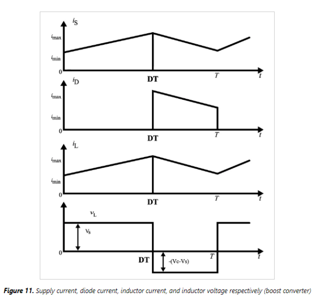
Describe Boost voltage/current waveforms.
I_S = supply current – increases when switch ON, slightly decreases when switch OFF (continuous)
I_D = diode current – zero when switch ON, conducts when switch OFF as inductor releases energy
I_L = inductor current – rises during switch ON, falls during switch OFF (triangle-shaped)
V_L = inductor voltage – positive (≈ Vₛ) during ON, negative (≈ Vₛ − Vₒ) during OFF
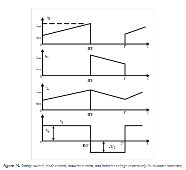
Describe Buck-Boost output polarity/waveform.
I_S = supply current – rises during switch ON, decreases when switch OFF
I_D = diode current – conducts when switch OFF as inductor reverses polarity
I_L = inductor current – rises during switch ON, discharges when switch OFF
V_L = inductor voltage – reverses polarity; positive during ON, negative during OFF


Explain how a Buck Converter circuit works
steps down the input voltage while stepping up current.
• When the switch (S) is ON, current flows through the inductor (L) to the load, storing energy in the magnetic field.
• When the switch turns OFF, the inductor releases stored energy through the diode (D) and capacitor (C), keeping current flowing to the load.
• Output voltage: V_o = D \times V_s where D is the duty cycle (0 < D < 1).

Explain how a Boost Converter circuit works
Steps up the input voltage while stepping down current.
• When the switch (S) is ON, the inductor (L) stores energy from the supply (V_s).
• When the switch turns OFF, the inductor releases its energy through diode (D) to the capacitor (C) and load, raising the output voltage above the input.
• Output voltage: V_o = \frac{V_s}{1 - D} .

Explain how a Buck-Boost Converter circuit works
Increase or decrease voltage, inverts polarity
• When the switch (S) is ON, the inductor (L) stores energy from the supply.
• When the switch turns OFF, energy is transferred through diode (D) to the capacitor (C) and load, reversing the voltage polarity.
• Output voltage: V_o = -\frac{D}{1 - D} V_s .
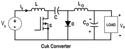
Explain how a Ćuk Converter circuit works
Provides inverted voltage and smooth current at both input and output.
• During ON period, switch (S) and inductor (L) transfer energy to capacitor (C).
• During OFF period, capacitor (C) discharges through diode (D) and second inductor (L_o) to the load.
• It combines features of buck and boost converters with lower ripple.
• Output voltage: V_o = -\frac{D}{1 - D} V_s .


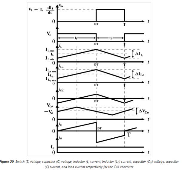
Explain the Cuk Converter voltage/current/output waveforms
V_S = supply voltage – provides energy to inductor L when switch is ON
V_C = coupling capacitor voltage – alternates between charging (switch ON) and discharging (switch OFF), transferring energy from input to output
I_L = input inductor current – increases when switch ON, decreases when switch OFF (continuous current)
I_{L_o} = output inductor current – decreases when switch ON (as capacitor charges), increases when switch OFF (as capacitor discharges to load)
V_{C_o} = output capacitor voltage – negative relative to input; small ripple as it smooths the output
I_C = capacitor current – alternates direction each cycle as it transfers energy between inductors
I_o = load current – approximately constant and continuous (smoothed by L_o)