Chapter 23: Electromagnetic Induction, AC Circuits, and Electrical Technologies
1/50
There's no tags or description
Looks like no tags are added yet.
Name | Mastery | Learn | Test | Matching | Spaced |
|---|
No study sessions yet.
51 Terms
back emf
the emf generated by a running motor, because it consists of a coil turning in a magnetic field; it opposes the voltage powering the motor
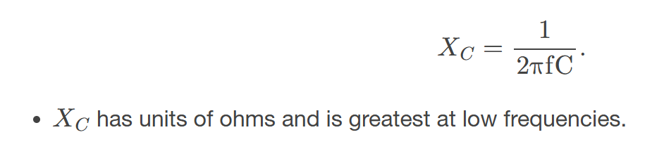
capacitive reactance
the opposition of a capacitor to a change in current; calculated by 𝑋𝐶=12πfC
characteristic time constant
denoted by 𝜏, of a particular series RL circuit is calculated by 𝜏=𝐿𝑅, where 𝐿 is the inductance and 𝑅 is the resistance
eddy current
a current loop in a conductor caused by motional emf
electric generator
a device for converting mechanical work into electric energy; it induces an emf by rotating a coil in a magnetic field
electromagnetic induction
the process of inducing an emf (voltage) with a change in magnetic flux
emf induced in a generator coil
emf=NAB𝜔sin𝜔𝑡, where 𝐴 is the area of an 𝑁-turn coil rotated at a constant angular velocity 𝜔 in a uniform magnetic field 𝐵, over a period of time 𝑡
energy stored in a inductor
self-explanatory; calculated by 𝐸ind=12𝐿𝐼2
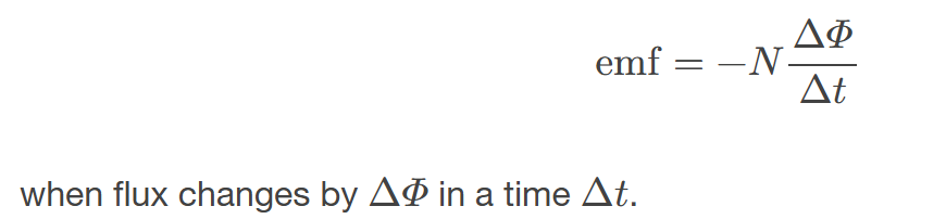
Faraday’s Law of Induction
the means of calculating the emf in a coil due to changing magnetic flux, given by emf=−𝑁𝛥𝛷𝛥𝑡
Henry
the unit of inductance; 1H=1Ω⋅s
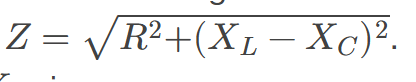
Impedance
the AC analogue to resistance in a DC circuit; it is the combined effect of resistance, inductive reactance, and capacitive reactance in the form 𝑍=√𝑅2+(𝑋𝐿−𝑋𝐶)2
Inductance
a property of a device describing how efficient it is at inducing emf in another device
Induction
(magnetic induction) the creation of emfs and hence currents by magnetic fields
Inductive reactance
the opposition of an inductor to a change in current; calculated by 𝑋𝐿=2πfL
Inductor
a device that exhibits significant self-inductance, the emf induced in it by a change in current through it is proportional to the rate of change of that current.
Lenz’s Law
the minus sign in Faraday’s law, signifying that the emf induced in a coil opposes the change in magnetic flux
Magnetic Damping
the drag produced by eddy currents
Magnetic Flux
the amount of magnetic field going through a particular area, calculated with 𝛷=BAcos𝜃 where 𝐵 is the magnetic field strength over an area 𝐴 at an angle 𝜃 with the perpendicular to the area
Mutual Inductance
how effective a pair of devices are at inducing emfs in each other
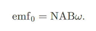
Peak emf
emf0=NAB𝜔
phase angle
denoted by 𝜙, the amount by which the voltage and current are out of phase with each other in a circuit
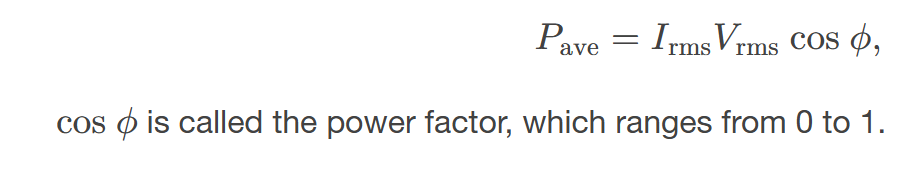
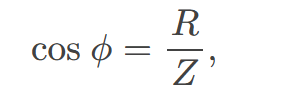
power factor
the amount by which the power delivered in the circuit is less than the theoretical maximum of the circuit due to voltage and current being out of phase; calculated by cos𝜙
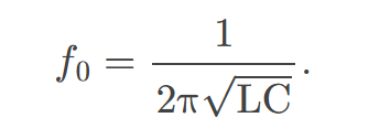
resonant frequency
the frequency at which the impedance in a circuit is at a minimum, and also the frequency at which the circuit would oscillate if not driven by a voltage source; calculated by 𝑓0=12π√LC
self-inductance
how effective a device is at inducing emf in itself
shock hazard
the term for electrical hazards due to current passing through a human
step-down transformer
a transformer that decreases voltage
step-up transformer
a transformer that increases voltage
thermal hazard
the term for electrical hazards due to overheating
three-wire system
the wiring system used at present for safety reasons, with live, neutral, and ground wires
transformer
a device that transforms voltages from one value to another using induction
transformer equation
the equation showing that the ratio of the secondary to primary voltages in a transformer equals the ratio of the number of loops in their coils; 𝑉s𝑉p=𝑁s𝑁p
Units of Magnetic flux
the measure of the total magnetic field that passes through a given area, measured in Weber (Wb). It quantifies the amount of magnetic field lines passing through a surface.
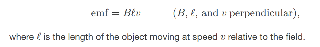
motional emf
the electromotive force generated when a conductor moves through a magnetic field, resulting in induced voltage.
An electric generator rotates a coil in a magnetic field, inducing an emfgiven as a function of time
that converts mechanical energy into electrical energy, producing alternating current.

Peak emf of a generator
is the maximum voltage output a generator can produce during its operation, typically occurring when its coil is aligned optimally with the magnetic field.
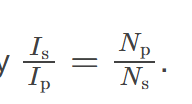
The currents 𝐼p and 𝐼s in the primary and secondary coils are related
through the turns ratio of the transformer, which determines how voltage and current change between the coils.
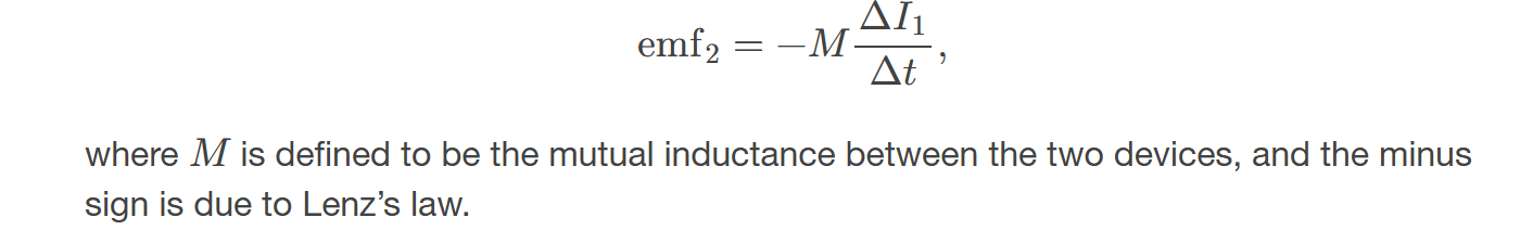
A change in current Δ𝐼1/Δ𝑡 in one
one induces an emf emf2 in the second according to Faraday's law of electromagnetic induction.
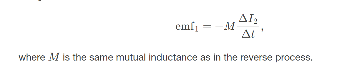
a change in current Δ𝐼2/Δ𝑡 through the second device
induces an emf emf1 in the first device, also based on Faraday's law of electromagnetic induction.
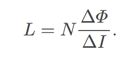
self-inductance 𝐿 of an inductor is
proportional to how much flux changes with current. For an 𝑁-turn inductor,
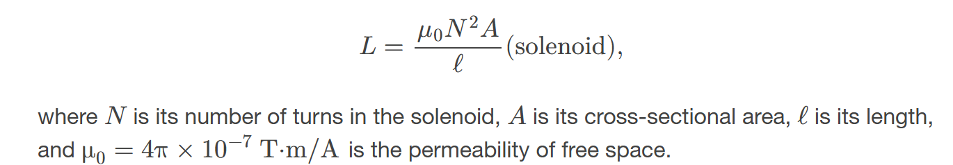
The self-inductance of a solenoid
is defined as the ratio of the induced emf to the rate of change of current in the solenoid, considering its geometry and the number of turns.
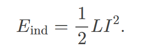
Energy stored in a inductor
is given by the formula ( U = \frac{1}{2} L I^2 ), where ( L ) is the inductance and ( I ) is the current through the inductor.
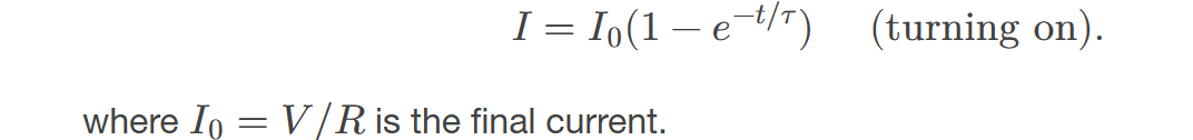
When a series connection of a resistor and an inductor—an RL circuit—is connected to a voltage source, the time variation of the current is
exponentially increasing and characterized by a time constant. This behavior results from the inductor opposing changes in current due to self-inductance.
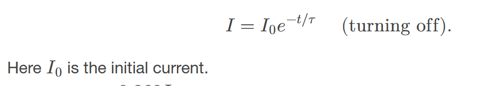
When the inductor is shorted through a resistor,
current decreases as
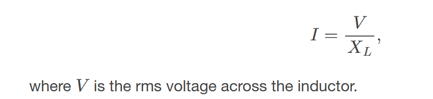
Ohm’s law for an inductor
states that the voltage across an inductor is proportional to the rate of change of current through it. Mathematically, it is expressed as V = L (dI/dt), where V is the voltage, L is the inductance, and dI/dt is the time rate of change of the current.
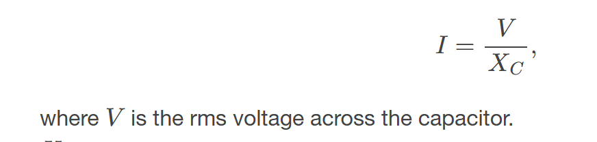
Ohm’s law for a capacitor
states that the current through a capacitor is proportional to the rate of change of voltage across it. Mathematically, it is expressed as I = C (dV/dt), where I is the current, C is the capacitance, and dV/dt is the time rate of change of the voltage.
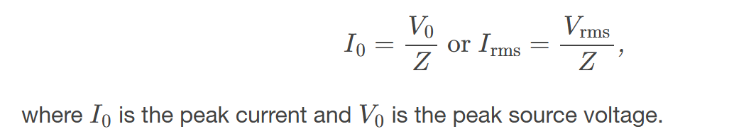
AC version of Ohm’s law:
states that the voltage and current in an AC circuit are related by the impedance of the circuit. It is often represented as V = I Z, where V is the voltage, I is the current, and Z is the impedance.
Impedance units
are measured in ohms (Ω), which indicate the opposition that a circuit presents to the flow of alternating current.
Resonant Frequency
at which 𝑋𝐿=𝑋𝐶
In an AC circuit, there is a phase angle 𝜙 between source voltage 𝑉 and the current 𝐼
due to the reactive components. This phase difference affects the power factor and the efficiency of energy transfer in the circuit.
for a purely resistive circuit or an RLC circuit at resonance.
The resonant frequency is the frequency at which the inductive reactance equals the capacitive reactance, resulting in maximum circuit current.

The average power delivered to an RLC circuit is affected by the phase angle and is given by
P = VI cos(φ)