Capacitors - Electromagnetism 7b - Model Answers
1/24
There's no tags or description
Looks like no tags are added yet.
Name | Mastery | Learn | Test | Matching | Spaced | Call with Kai |
|---|
No study sessions yet.
25 Terms
Define capacitance.
C = Q/V : the charge stored on each plate of a capacitor required to cause a unit change in the potential of a conductor.
What is the unit of capacitance?
The Farad, F = CV-1
Describe the structure of a capacitor.
Two conductors, such as a pair of parallel metal plates, separated by an insulator (sometimes referred to as a dielectric).
Write the symbol for a capacitor.
SEE image

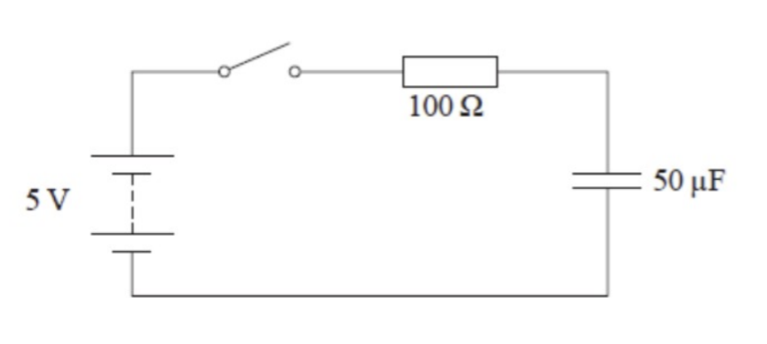
Draw a circuit diagram to illustrate a circuit that would allow a capacitor to charge and discharge.
SEE image

Explain how a capacitor becomes charged and what happens to the current in the circuit (using the circuit in the previous question).
When the sliding switch is connected to the charging position, the capacitor is conneced across a cell with pd V0.
Electrons will move anticlockwise around this circuit, being removed from the top capacitor plate, making it positively charged and being added to the bottom plate of the capacitor, making it negatively charged. (Electrons do not pass trhough the capacitor as there is an insulating material preventing this.)
The pd across the capacitor increases and the pd across the resistor R decreases.
Current decreases exponentially during this charging process.
This is because the current in the circuit is I = V/R, where V is the pd across the resisitor and R is the resistance of the resistor, and as V across the resistor decreases, so does the current.
Charging will stop (current will be zero) when the potential difference across the capacitor matches the potential difference across the cell.
Explain how a capacitor becomes discharged (using the circuit in the previous question).
When the sliding switch is connected to the discharging position, electrons leave the negatively charged lower plate and flow anticlockwise around this circuit through the resistor to the positive capacitor plate.
When electrons join the positive capacitor plate, its charge decreases exponentially and the potential difference across the capacitor will decrease exponentially.
Current decreases exponentially.
Until there is an equal charge on each of the capacitor plates, and the pd across the capacitor is zero. Discharging stops.
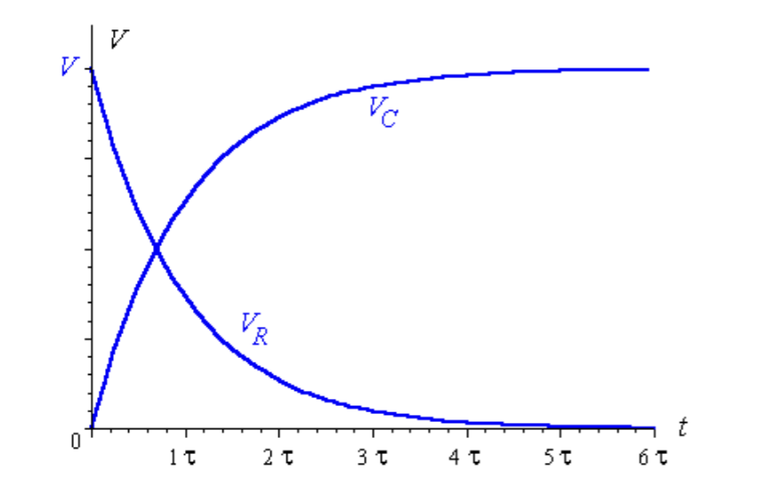
a) Explain what happens to the pd across the resistor and the pd across the capacitor after the switch is closed.
b) Sketch a graph showing the pd across the capacitor and the pd across the resistor over time.
a)
The emf must always equal to the sum of the pd drops across the capacitor and resistor.
The pd across the capacitor starts at 0V and increases (at a decreasing rate) to a maximum value of 5V.
The pd across the resistor starts at 5V, and decreases exponentially to 0V.
c) Explain what happens to the current in the circuit when the switch is closed,
The current in the circuit is given by I = V/R, where V is the pd across the resistor and R is the resistance of the resistor.
Initially, the current is maximum, equal to the emf/R as the resistor receives the full share of the cell’s emf.
As the capacitor charges, the pd across the capacitor increases and the pd across the resistor decreases exponentially.
Eventually (after approx 5 time constants), the current through the circuit is zero, as the pd across the resisitor is zero and the pd across the capacitor is equal to the cell’s emf.
State three equations for the energy stored in a capacitor.
W = ½ QV
Substituting the equation for capacitance, C = Q/V, we can derive two more equations:
W = ½ Q²/C
W = ½ CV²
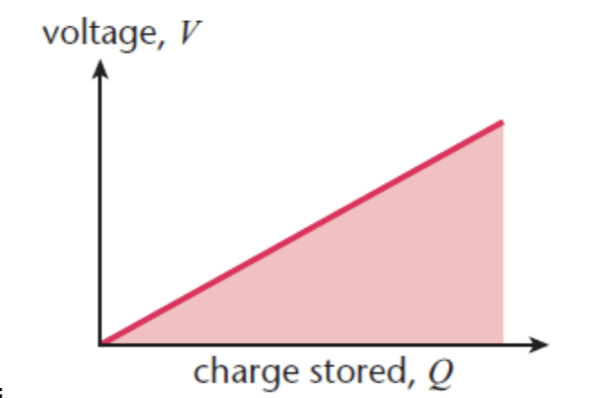
Justify the equation W = ½ QV
The work done is the area under the Q, V graph
As the charge is added to the capacitor, the pd increases across it in proportion to the charge. So the area under this graph is ½ QV
Define time constant.
The time constant represents the time it takes for the pd to fall to about 37% during discharging.
Define exponential decay.
Exponential decay is when a quantity decreases by the same factor in equal time intervals.
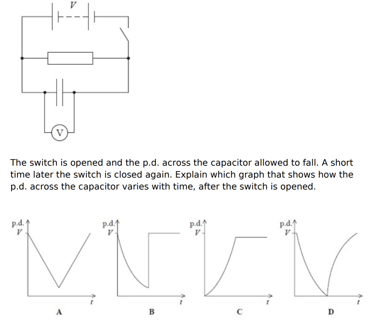
The capacitor shown in the circuit below is initially charged to a potential difference V by closing the switch. The power supply has negligible internal resistance.
The switch is opened and the pd across the capacitor is allowed to fall. A short time later, the switch is closed again. Explain which graph shows how the pd across the capacitor varies with time, after the switch is opened.
Answer: Graph B
The pd at t=0 must be equal to the pd of the cell, as the capacitor has initially been charged by closing the switch.
When the switch is opened, the capacitor discharges exponentilly through the resisitor. This happens exponentially because V = V0 e-t/RC
When the switch is closed again, the capacitor charges again.
This takes almost no time as there is no resistor in the charging circuit with the capacitor and the cell. The current would be very high for a very short time, building up the charge on each capacitor plate.Once the capacitor’s pd equalled that of the cell, current would become zero and the pd would remain constant.
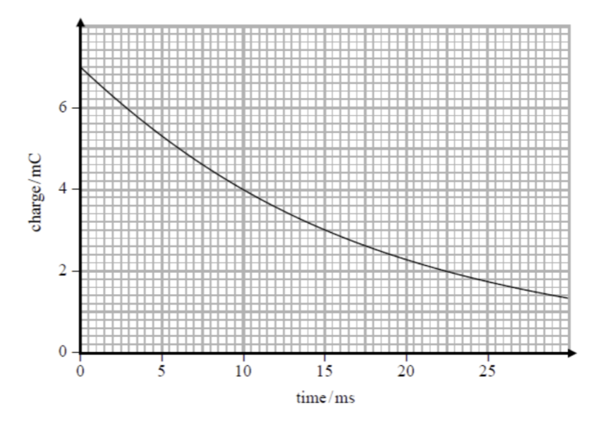
Show that the following charge time graph for a capacitor discharging illustrates exponential decay.
At t = 0ms, Q = 7.0 mC
t = 5ms, Q = 5.3 mC
Factor by which Q decreases in the first 5ms is 5.3/7 = 0/757
t = 10ms, Q = 4.0 mC
Factor by which Q decreases in the second 5ms is 4.0/5.3 = 0.755
So the factor by which Q decreases is equal, in equal time intervals.
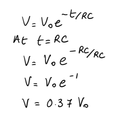
Prove that after a time equal to the time constant, RC, the pd will have fallen to 37% of its original value.
SEE proof
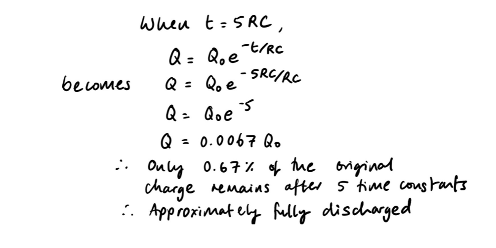
Prove that the capacitor can be approximated to have discharged after a time equal to 5 time constants.
SEE proof
Derive the expression for the half-life of a capacitor.
SEE derivation : from V0 to ½ V0

Calculate the time taken for 20% of the chage to remain on a 50μF capacitor if it is discharging through a 100kΩ resistor.
For 20% of the charge to remain, Q = 0.2 Q0
Q = Q0 e-t/RC
0.2 Q0 = Q0 e-t/RC
ln (0.2) = -t / (1×105 × 50×10-6)
t = 8.05 s

A capacitor is discharged through a resistor of resistance 900Ω. The graph shows how the charge on a capacitor decreases with time. Expalin 2 different approaches you could take to determining the capacitance of this capacitor.
Method 1: Finding the time constant and dividing by R
Q0 = 7.0 mC
So Q at the time equal to the time constant will be Q = 0.37 x Q0 = 0.37 × 7.0 = 2.6 C
2.6 C occurs at a time equal to 17ms (reading from the graph)
RC = 17 × 10-3
C = (17 × 10-3) / 900 = 0.019 mF
Method 2: Substituting values into Q = Q0 e-t/RC
Q0 = 7.0 mC
Choose a position on the graph and read Q and t, e.g. at t = 10 ms, Q = 4.0 mC
Substutite into Q = Q0 e-t/RC
4.0×10-3 = 7.0×10⁻³ e-0.01/900C
ln(4/7) = 0.01/900C
C = -0.01 / (900 x ln(4/7))
C = 0.020 mF

A student is investigating how the potential difference across a capacitor varies with time as the capacitor is charging. He uses a 100μF capacitor, a 5.0 V DC supply, a resistor, a voltmeter and a switch.
a) Calculate the maximum charge stored on the capacitor.
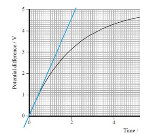
b) The graph shows how the pd across the capacitor varies with time as the capacitor is charging. Estimate the average charging current over the first 10 ms.
a) Q = CV = 100×10-6 × 5 = 5 × 10⁻⁴ C
b) Average charging current = total charge / total time = 5.0×10⁻⁴ /10×10-3 = 0.05 A
c)
A student is investigating how the potential difference across a capacitor varies with time as the capacitor is charging. He uses a 100μF capacitor, a 5.0 V DC supply, a resistor, a voltmeter and a switch.
c) Use the graph to esitmate the initial rate of increase of pd across the capacitor and hence find the initial charging current.
From the tangent, ∆V/∆t = 5/(2.1×103) = 2.38×10³ Vs-1
Initial current = ∆Q / ∆t = C∆V/ ∆t = 100×10-6 × 2.38×103 = 0.24 A
A student connected a capacitor to a cell through a resistor and allowed it to charge. After discharging this capacitor, the student then connected another capacitor in series with the first and charged both. Explain how the charge stored on each capacitor compares to the charge stored on the single capacitor.
Each capacitor will now have a maximum pd across it, equal to half the original capacitor’s maximum pd as the emf is shared between the two capacitors in series.
This means that the capacitors’ maximum charge will be hald of the orginal capacitor’s charge.
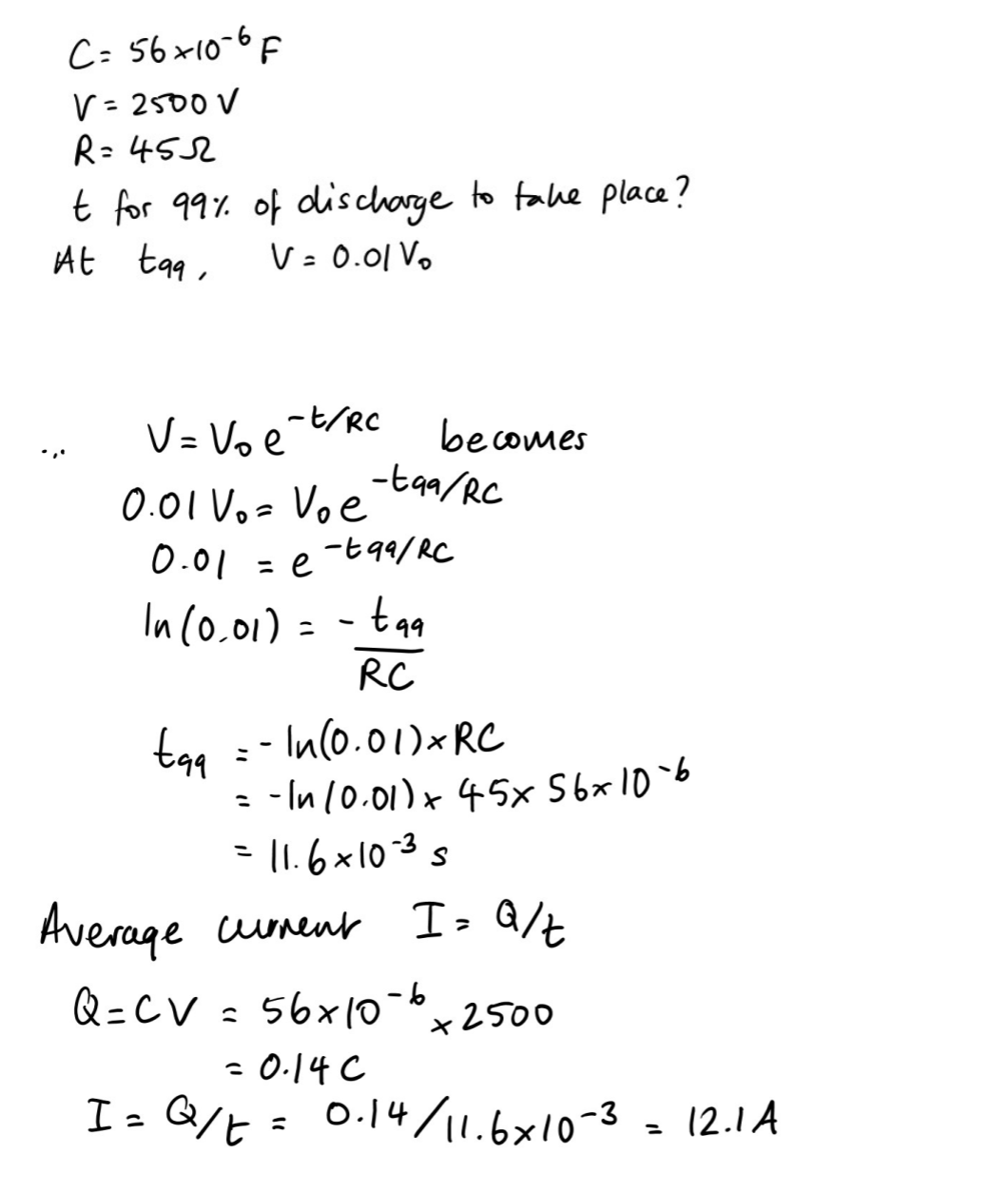
A defibrillator is an electrical device designed to deliver a brief electrical signal to restore a normal rhythm to the heart. Electrodes are attached to the chest of a patient and a charged capacitor is discharged through the chest cavity.
In one defibrillator, a 56μF capacitor is charged by a pd of 2500V. During the discharge of the capacitor, the resistance between the electrodes is 45Ω.
Show that the time taken for 99% of the discharge to take place is about 12 ms and hence calculate the average current deivered by teh defibrillator during thsi period. [6]
SEE solution
Cameras usually have an inbuilt flash bulb that can be used to take photographs in poor light conditions. As a photograph is taken, the bulb should be able to produce a bright flash of light for up to 4 ms.
A capacitor can be used along with a battery as a power supply for the flash bulb. The flow diagram shows a possible arrangement.
Comment on the suuitability of using this capacitor arrangement as a power supply rather than connecting the bulb directly to the battery.
A typical flash bulb has a resistance of 6Ω. [6]
The capacitor can be charged to a higher pd than that of the battery.
This allows more energy to be stored by the capacitor as W = ½ CV²
As the bulb has a low resistance of 6Ω, the capacitor would discharge rapidly.
The time constant RC would be 6 × 185×10-6 = 1.1ms
The capacitor would have fully discharged after approximately 5 time constants, so this would take 5.5ms. This is higher than the 4ms requirement.
At 4ms, the capacitor would have discharged to 2.7% of its original charge, so this can also be approximated as full discharge and the current would be minimal by 4ms.
The average power of the flash = (energy transferred)/ time, so with a high energy store and a short time, the power would be high and the flash would be bright.