ENG 004 Final
0.0(0)
Card Sorting
1/101
Earn XP
Description and Tags
Last updated 4:56 AM on 12/5/22
Name | Mastery | Learn | Test | Matching | Spaced | Call with Kai |
|---|
No analytics yet
Send a link to your students to track their progress
102 Terms
1
New cards
Visual Thinking
A phenomenon of thinking through visual process
2
New cards
Visualization Methods
Sketching and CAD
3
New cards
3 roles of graphics in design
Visualization, Communication, Documentation
4
New cards
Visualization
- Ability to see object in your mind
- Sketches are the first physical capture of your mental image
- Sketches are the first physical capture of your mental image
5
New cards
Communication
- Refine drawings and models• To improve the clarity of graphics
- Communication of idea with others
- Communication of idea with others
6
New cards
Documentation
- Detailed 3D and 2D drawings
- Contains all information needed to create/manufacture/use object(s)
- Contains all information needed to create/manufacture/use object(s)
7
New cards
Ideation
the formation of ideas or concepts
8
New cards
Linear Engineering Design
Traditional Engineering Design
9
New cards
Model-centered engineering design
3 major activities: Ideation, refinement, implementation
10
New cards
Sketching vs. Drawing
-Sketching: Transferring of ideas or concepts onto paper or into a computer to quickly capture them graphically.
-Drawing: Transferring of an object's size, shape, proportion and/or main features onto paper or into a computer.
-Drawing: Transferring of an object's size, shape, proportion and/or main features onto paper or into a computer.
11
New cards
Design Sketch
Rough sketches that are used to quickly capture an idea. They tend to have less detail, structure and restrictions than freehand or technical illustrations.
12
New cards
Technical Illustration
Detailed drawing with restrictions, dimensions, and structures.
13
New cards
Contour Sketching
sketching the outline of an object
14
New cards
ANSI (American National Standards Institute)
The national standards institute of the
United States, which facilitates the
formation of a variety of national standards for STEM
United States, which facilitates the
formation of a variety of national standards for STEM
15
New cards
ISO (International Standards Organization)
The organization which sets the international standard for manufacturing.
16
New cards
ASME (American Society of Mechanical Engineers)
A professional engineering organization that is known for setting codes and standards for mechanical devices in the United States.
17
New cards
Visible Lines
used to represent features that can be seen in the current view
18
New cards
Dimension and Extension Lines
used to indicate the sizes of features on a drawing
19
New cards
Hidden Lines
used to represent features that cannot be seen in the current view
20
New cards
Center Lines
lines that define the center of an arc,circle, or symmetrical parts.
21
New cards
Cutting Plane Lines
used in section drawings to show the locations of cutting planes
22
New cards
Section Lines
Thin lines used in a section view to indicate where the cutting plane line has cut through material.
23
New cards
Break Lines
Lines used to terminate features on a drawing when the extent of the feature has been clearly defined and no additional detail is needed.
24
New cards
Isometric Sketch
A form of pictorial sketch in which all three drawing axes form equal angles of 120 degrees with the plane of projection.
-Orthographic Projection
-Orthographic Projection
25
New cards
Oblique Sketch
The object face that is placed parallel to the frontal plane will be drawn true size and shape
-Non-orthographic projection
-Non-orthographic projection
26
New cards
single point perspective
A technique for achieving a sense of depth by establishing a single vanishing point and painting or building all objects to diminish to it.
-Non-Orthographic
-Non-Orthographic
27
New cards
Vanishing Point
A point in space, usually located on the horizon, where parallel edges of an object appear to converge.
28
New cards
Ground Line
a base line upon which figures stand
29
New cards
two point perspective
two vanishing points
-Non-Orthographic
-Non-Orthographic
30
New cards
Multi-View Drawing
A drawing which contains views of an object projected onto two or more orthographic planes.
-Orthographic
-Orthographic
31
New cards
Cartesian Coordinate System
A rectangular coordinate system created by three mutually perpendicular coordinate axes, commonly labeled X, Y, and Z. Can be 2D with just XY plane
32
New cards
polar coordinate system
A two-dimensional coordinate system in which each point on a plane is determined by a distance from a reference point and an angle from a reference direction.
33
New cards
Spherical Coordinate System
Uses angular measurements on a sphere to specify locations (r, φ, θ)
x = r cosφ cosθ
y = r sinφ
z = r cosφ sinθ
x = r cosφ cosθ
y = r sinφ
z = r cosφ sinθ
34
New cards
cylindrical coordinate system
(r, θ, z)
- x = r cosθ
- y = r sinθ
- x = r cosθ
- y = r sinθ
35
New cards
Absolute Coordinates
The exact location of a specific point in terms of X, Y, and Z from the fixed point of origin
36
New cards
Relative Coordinates
The location of a point as given by the distance from the last point specified.
37
New cards
World Coordinates
- "Stationary" or "Fixed"
- Never changes position or orientation relative to the model
- Never changes position or orientation relative to the model
38
New cards
Local Coordinates
- Coordinate system defined by the designer or CAD system.
- May located and oriented anywhere in any direction within the world coordinate systems.
- May located and oriented anywhere in any direction within the world coordinate systems.
39
New cards
Primitives
the building blocks/elements used to create CAD models
40
New cards
Node
Most basic primitive. A single point.
41
New cards
Spline Curve
A spline curve is a smooth, freeform curve that connects a series of control points.
42
New cards
Interpolated curve
Every point is on the spline curve
43
New cards
Bezier Curve
Spline with two endpoints and control points to specify curve direction.
44
New cards
B-Spline
Higher level of complexity of Bezier. degree of curve can be changed without changing # of points. several curves joined at knots
45
New cards
Geometric Constraint
Constant, non-numerical relationships between the parts of a geometric figure. Examples include parallelism, perpendicularity, and concentricity.
46
New cards
Conditions vs. Constraints
• Conditions are like constraints, but they are not enforced.
• Conditions are simply the geometric state of the feature.
• Conditions are simply the state of the feature at a given moment or location.
• Constraints remain enforced until the designer releases them.
• Conditions are simply the geometric state of the feature.
• Conditions are simply the state of the feature at a given moment or location.
• Constraints remain enforced until the designer releases them.
47
New cards
Generatrix
a point, line, or surface whose motion generates a line, surface, or solid
48
New cards
Directrix
fixed line
49
New cards
Steps to create a solid model
1. Define workplane
2. Define profile (Sketch)
3. Solid Geometric Modeling
2. Define profile (Sketch)
3. Solid Geometric Modeling
50
New cards
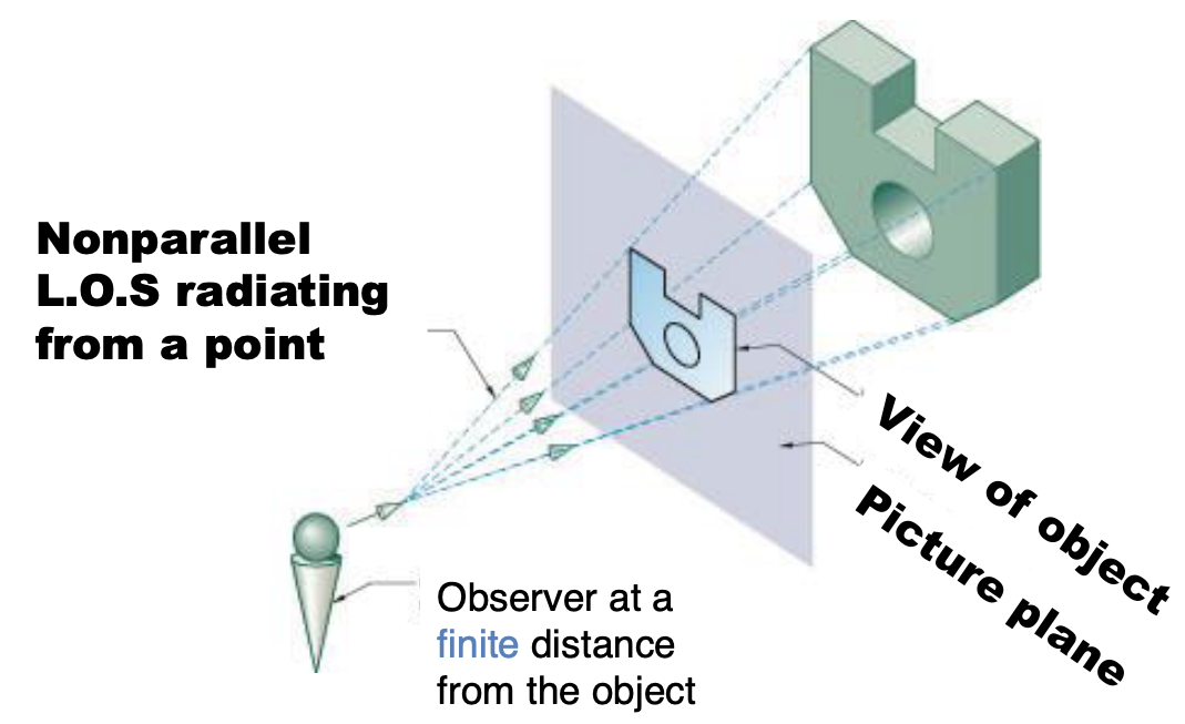
Perpective Projection
- Line of sight radiates from the observer
- The most realistic natural view
- The most realistic natural view
51
New cards
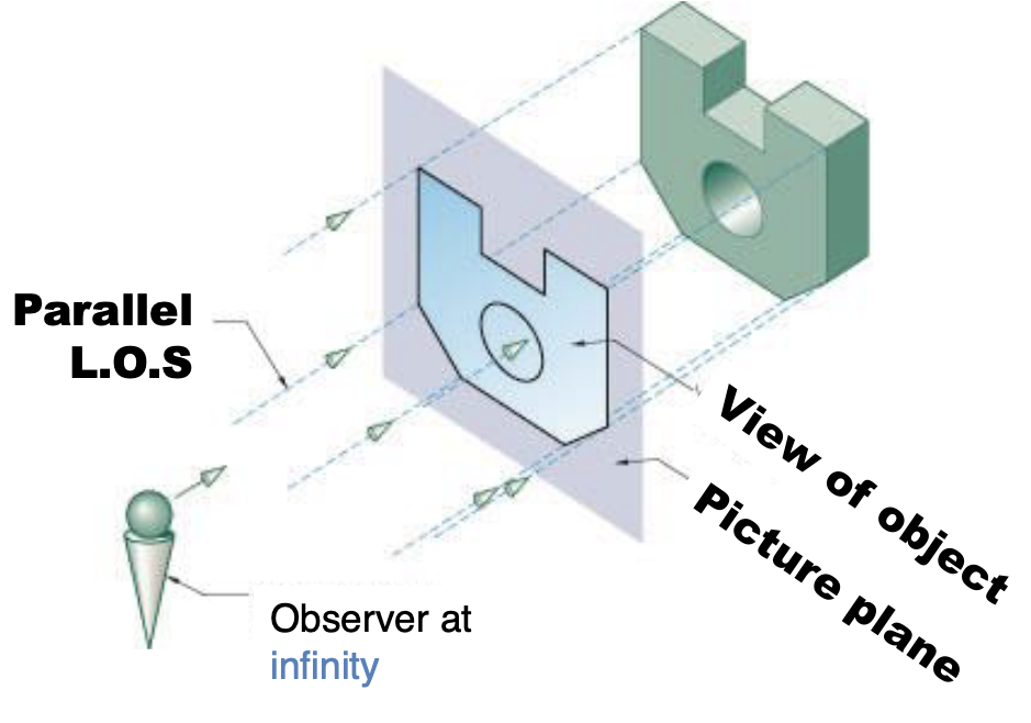
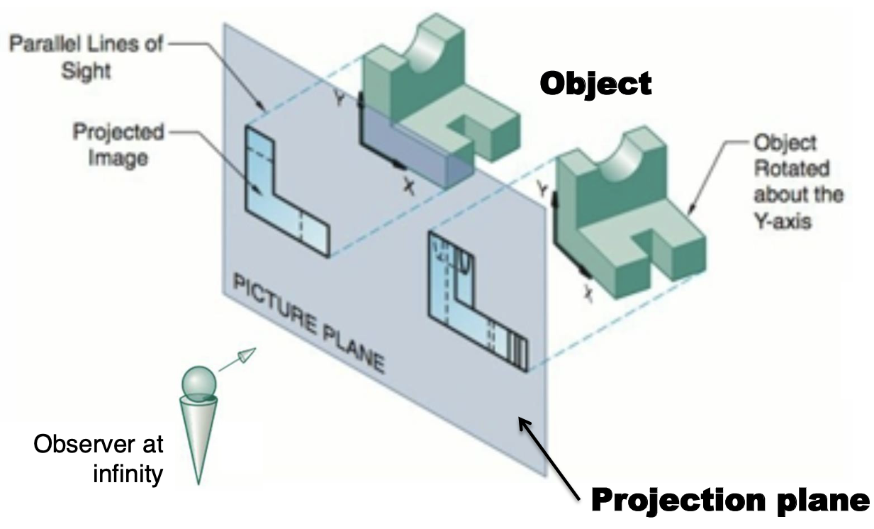
Parallel Projection
Line of sight is parallel to the observer
52
New cards
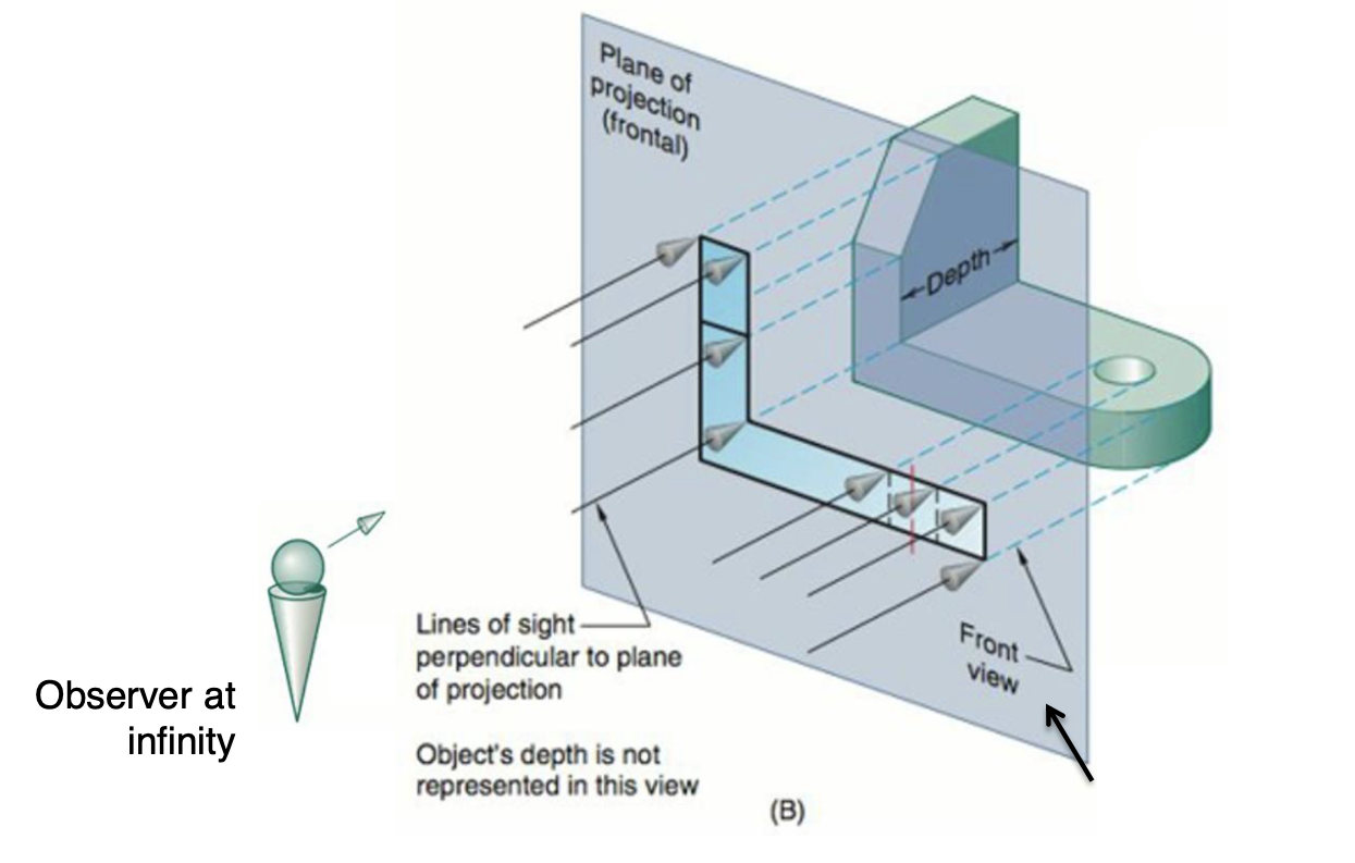
Orthographic Projection
Line of sight is perpendicular to the projection plane
53
New cards
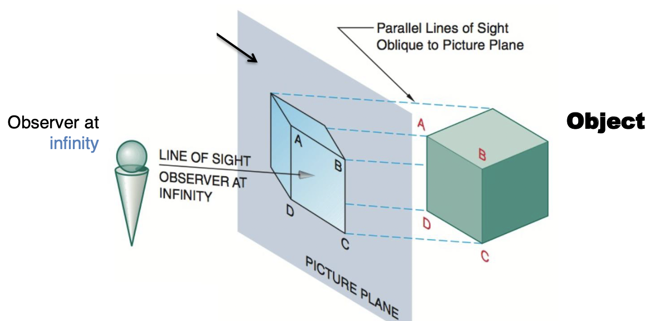
Oblique Projection
Line of sight is not perpendicular to the projection plane
54
New cards
Axonometric Projection
- Line of sight perpendicular to projection plane
- A type of orthographic projection
- Parallel projection technique
- A type of orthographic projection
- Parallel projection technique
55
New cards
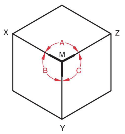
Isometric
- Type of Axonometric Projection
- Angles A, B, and C are equal
- Corners MZ, MX, and MY are equal in length
- Angles A, B, and C are equal
- Corners MZ, MX, and MY are equal in length
56
New cards
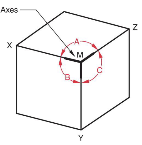
Dimetric
- Type of Axonometric Projection
- Angles A and C are equal
- Corners MX and MY are equal in length
- Angles A and C are equal
- Corners MX and MY are equal in length
57
New cards
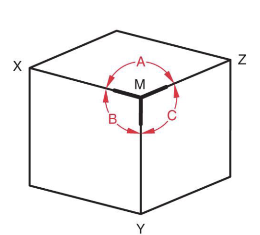
Trimetric
- Type of Axonometric Projection
- No equal angles or corners
- No equal angles or corners
58
New cards
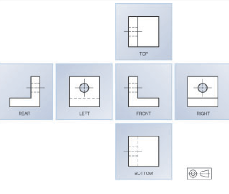
Third Angle Projection
Used by ANSI and JIS
59
New cards
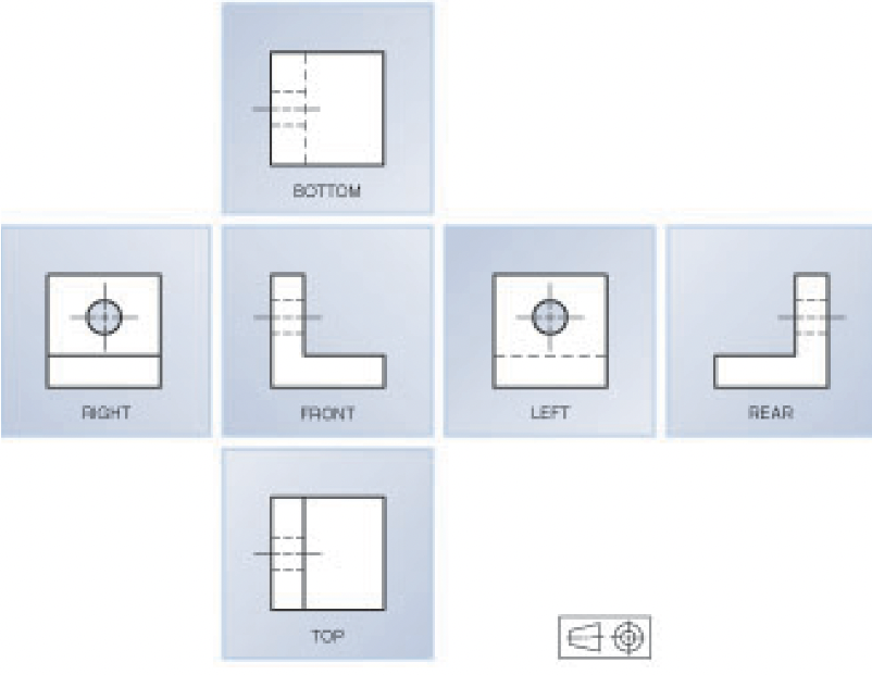
First angle projection
Used by ISO and DIN
60
New cards
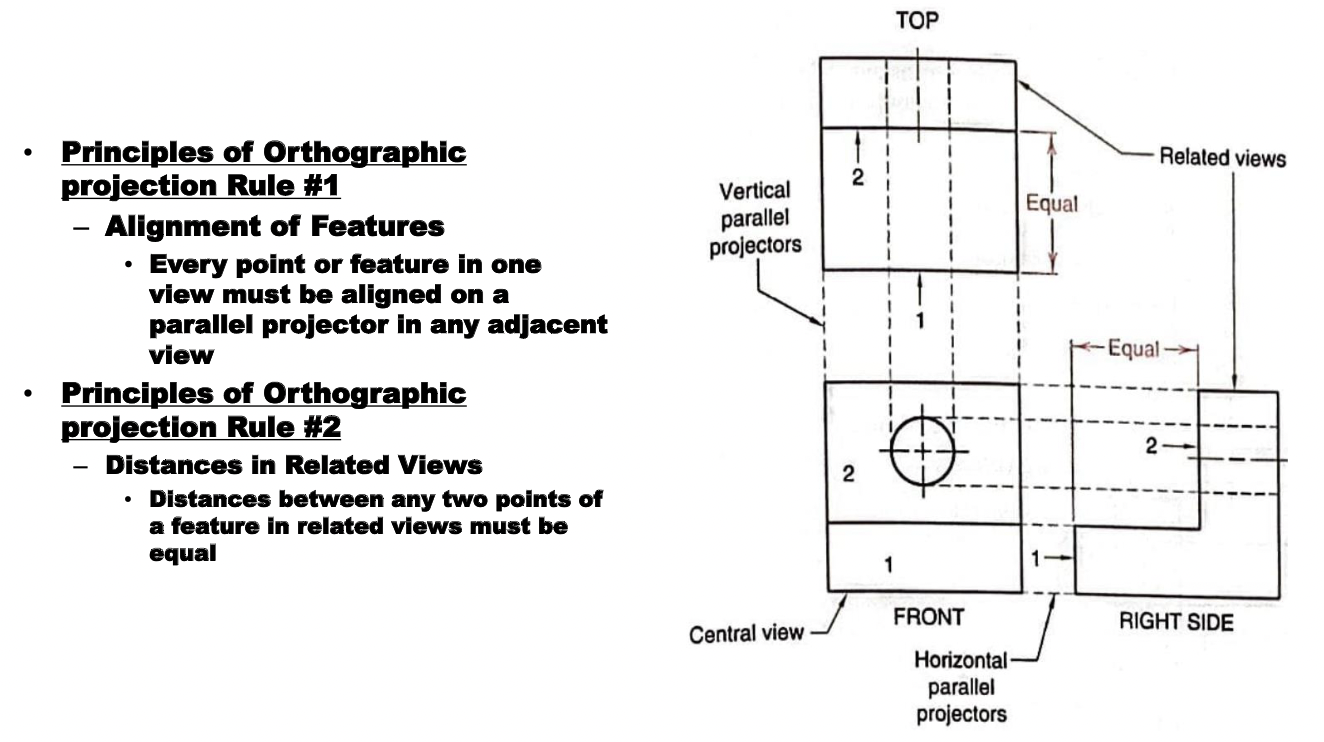
Principles of Orthographic Projection
- Alignment of feature
- Distances of related views must be equal
- Distances of related views must be equal
61
New cards
True Size (TS)
LOS are perpendicular to the feature
62
New cards
Edge View/Point View (EV or PV)
LOS are parallel to feature
63
New cards
Oblique View (OV)
LOS are neither parallel nor perpendicular to feature
64
New cards
Default Tolerance
Tolerance used when it is not otherwise specified
65
New cards
Reference Symbol
( )
66
New cards
Places/Times Symbol
X
67
New cards
Counterbore

68
New cards
Countersink

69
New cards
Depth

70
New cards
Dimensional Tolerence
Tolerance of size and location
71
New cards
Geometric Tolerence
Tolerance of form (Perpendicularity, flatness, etc)
72
New cards
Inch Dimensions
- # of decimals equal (ex: 8.900 and 4.896)
- No 0 before decimals under 1 (ex: .98)
- No 0 before decimals under 1 (ex: .98)
73
New cards
Metric Dimensions
- # of decimals not equal (ex: 8.9 and 4.896)
- Include 0 before decimals under 1 (ex: 0.98)
- Include 0 before decimals under 1 (ex: 0.98)
74
New cards
Maximum Material Condition (MMC)
Size of a feature at one end of its tolerance zone where
there is the most amount of material.
there is the most amount of material.
75
New cards
Least Material Condition (LMC)
Size of a feature at one end of its tolerance zone where
there is the least amount of material.
there is the least amount of material.
76
New cards
Class of Fit
An assembly of two parts creates a “fit” whose
functional characteristics is determined by the
difference in the parts’ associated sizes.
functional characteristics is determined by the
difference in the parts’ associated sizes.
77
New cards
Clearance Fit
MMCH > MMCS
- Always leaves space when assembled
- Always leaves space when assembled
78
New cards
Interference Fit
LMCH < LMCS
- Parts always intersect when assembled
- Parts always intersect when assembled
79
New cards
Allowance
Smallest hole - largest fit =
80
New cards
Transition Fit
Two toleranced mating parts are sometimes an interference fit and. sometimes a clearance fit when assembled.
- MMCH > LMCS
- LMCH < MMCS
- MMCH > LMCS
- LMCH < MMCS
81
New cards
ISO fit recommendations
■ Capital letters refer to the hole
■ Lowercase letters refer to the shaft
■ Basic size is the nominal size of both members
■ Lowercase letters refer to the shaft
■ Basic size is the nominal size of both members
82
New cards
Hole Symbol
Capitol letter
83
New cards
Shaft Symbol
Lowercase letter
84
New cards
Fit Symbol
Hole tolerance/shaft tolerence
ex. H8/f7
ex. H8/f7
85
New cards
Feature control frame
Used to specify the geometric tolerance. It is divided into two or more zones.
86
New cards
Datum
Reference point or surface
87
New cards
Straightness (FORM)
compares a line on a part to a perfectly straight line.

88
New cards
Circularity (FORM)
evaluates a circle to a perfect circle.
89
New cards
Flatness (FORM)
evaluates the largest vertical distance
between the highest and lowest points on a surface (plane).
between the highest and lowest points on a surface (plane).
90
New cards
Cylindricity (FORM)
compares a cylinder to a perfect cylinder.
91
New cards
Parallelism (ORIENTATION)
Specifies the degree to which a feature's orientation may vary with respect to its referenced datum by creating a tolerance zone parallel to that datum.

92
New cards
Perpendicularity (ORIENTATION)
Specifies the degree to which the orientation of a right-angled part feature may vary.
93
New cards
Concentricity (LOCATION)
he condition in which the axes of
all cross-sectional elements of a cylinder (cone or sphere)
are common to a datum axis.
all cross-sectional elements of a cylinder (cone or sphere)
are common to a datum axis.
94
New cards
Circular runout (RUNOUT)
Used to control the location of a circular part feature relative to an axis.
95
New cards
Section views
Clarify the interior geometry by removing a portion of a part in a sketch
96
New cards
Cast Iron
Material used for the general section lines
97
New cards
Full Sections
Made by passing the imaginary cutting plane completely through the object.
98
New cards
Half Sections
Show features of up to ½ of the part (Usually these parts have circular symmetry.)
99
New cards
Offset sections
Used to include features not found
on a single plane but on parallel planes.
on a single plane but on parallel planes.
100
New cards
Aligned Sections
Used to show features not on a single cutting plane, nor parallel cutting planes, but on cutting planes that intersect through a single axis.