physics A michaelmas: OWO
1/57
There's no tags or description
Looks like no tags are added yet.
Name | Mastery | Learn | Test | Matching | Spaced | Call with Kai |
|---|
No analytics yet
Send a link to your students to track their progress
58 Terms
damped driven oscillation standard equation
x°° +γx° +ω₀²x =F/m
ω₀² = k/m , γ = b/m
response function
relation to displacement
how it's derived
R(ω)= 1/(m[(ω₀²− ω²) + iγω])
x₀ = R(ω)F₀
derived by sub x=Re{x₀exp(iωt)}
Q factor
formula
formula with bandwidth
ω/ω₀ using Q
Q = ω₀/γ = ω₀/∆ω
ω/ω₀ = √(1-1/(2Q²))
mean power required to drive a damped, driven oscillator, using complex notation and impedance
= 1/2 Re{F₀v₀*} = 1/2 Re{Z} |v₀|²
LCR series electrical circuit ω₀, γ, x
ω₀² = 1/(LC)
γ = R/L
x = q
impedance
Z = F0/v0
transient response x= Aexp(p1t) +Bexp(p2t)
what are p1 and p2?
p1,2 = (-γ+- √(γ²-4ω₀²) )/2
critical damping definition and Q value
Q = 0.5
special case, where only one value of p exists. decays the fastest.
wave on a string:
force
velocity
impedance
mean power
F = -T ∂Ψ/∂x
v = √(T/ρ)
Z = ρv
= 1/2 Re{Z}|u|² = 1/2 Zω²A₀²
note u=∂t/∂Ψ , v is the traverse volcity
reflected and transmitted amplitude upon transition from Z1 to Z2
how are they derived
what happens to the phase if Z2 is bigger than Z1, or smaller
r = (Z1-Z2)/(Z1+Z2)
t = (2Z1)/(Z1+Z2)
derived by continuity of Ψ and force: Ψ1 = Ψ2 and T(∂Ψ1/∂x) = T(∂Ψ2/∂x)
Z1 > Z2:
reflected inverts (r<0).
Z2 > Z2:
reflected doesn't invert (R>0).
transmitted doesn't invert for both because t>0 always.
impedance matching
idea
somethng
to transmit waves from one medium to another. To obtain as high a level of energy transmission as possible it is essential to minimise reflection at the boundary.
adiabatic relation between temperature and pressure
adiabatic implyes constant T - no time for any heat exchange.
p = V^γ
γ = C_p/C_v
pressure wave formula
Ψp = −γp ∆V/V = −γp ∂a/∂x
or Ψp = iγpka
(using a = a0 exp i(ωt − kx) )
where a is the wave displacement.
pressure wave speed
v = √(γp/ρ) = √(γRT/m)
pressure wave speed in solids and liquids using modulus
bulk modulus definition
v =√(K/ρ)
in liquids: K = B, where B is defined by dp = -B dV/V
in solids: K = Y, where Y = dp / ∂a/∂x
3D wave equation
∇²Ψ = 1/v² ∂²Ψ/dt² .
formula for wave from a point disturbance at the origin
Ψ(r, t) = A/r exp( i(ωt−k|r|) )
hence intensity proportional to Ψ² decays as 1/r²
standing wave formula with boundary conditions
= 2A sin(ωt) sin(kx)
boundary conditions: k = nπ/b (b is the length of the media). so only a number of frequencies are permitted.
Dispersive Waves: dispersion types
anomalous dispersion: is the common behavior where a material's refractive index decreases as wavelength increases (blue light bends more than red like rainbows of prisms.
Anomalous dispersion: the refractive index increases with wavelength reversing the normal order and leading to effects like negative chirping in optical pulses.
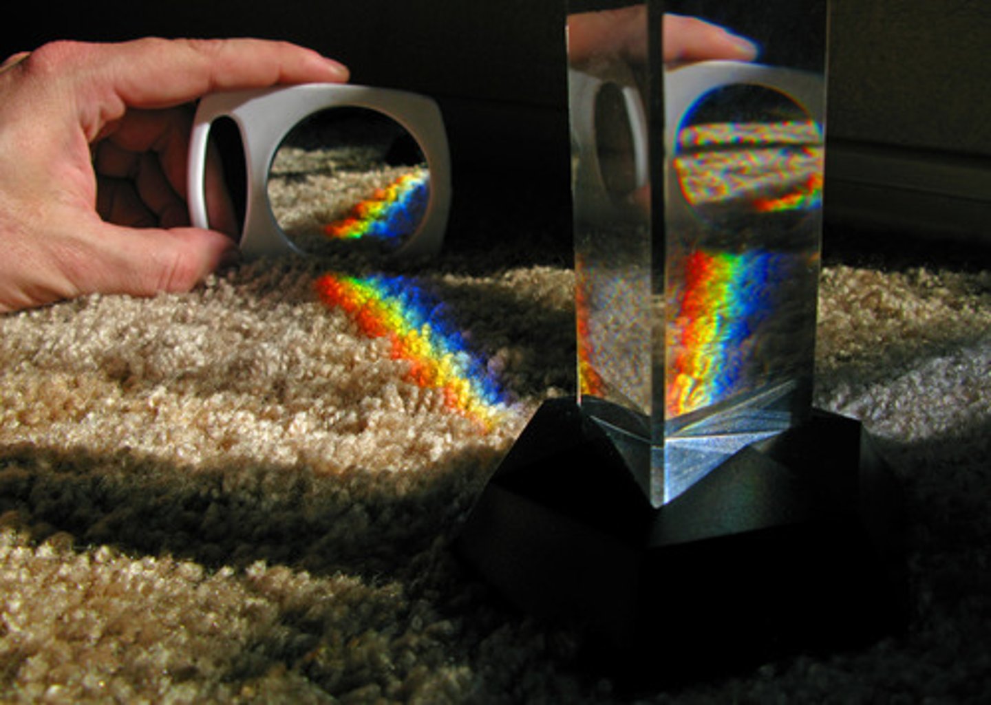
phase velocity and group velocity
v_g = ∂ω/∂k
v_p = ω/k
wave in a waveguide (x direction) equation
Ψ = −2iA sin (kyy) exp i(ωt − k_x x)
F.T of a delta function δ(t - t₀)
exp(-iωt₀)/√(2π)
F.T of a top hat
sin(ω/2)/(√(2π) ω/2 )
F.T of a gaussian
exp(-t²/2)
exp(-ω²/2)
F.T of a decaying exponential exp(-t) for t>0
1/ [√(2π) (1+iω ) ]
F.T of a comb function Σδ(t-n)
√(2π)Σδ(ω-2πn)
impedance in terms of permittivity and permeability
Z = √(µ/ε)
where µ = µ₀µ_r and ε = ε₀ε_r
obliquity factor, K(θ) formula and what is it
describes the fall-off in intensity of the wavelets with angle, θ, away from the forward direction
K(θ) = ( 1 + cos θ )/ 2
Fresnel-Kirchhoff (general) diffraction integral
ψ_P =∫∫− i/λ h(x, y) K(θS, θP) a_S exp(ik(s+r))/ (s r) dx dy
Fraunhofer Diffraction:
when to use
what assumption are made to simplify the general integral
planar incidence (far source or lens), small angle for the aperture - P.
assumptions: K(θS,θP)≈const, a_S / s ≈ const
condition: k(x²+y²)/(2R) << π
the Fraunhofer integral for 2D and 1D
2D
ψ_P ∝∫∫h(x,y) exp[-ipx-iqy] dx dy
where (x0, y0) are the coordinates of point P on the. screen, R is the origin to P distance
1D
ψP ∝ ∫ h(y) exp(−ikq) dy = FT{h(y)}
where q = y sin θ
two narrow slits Fraunhofer diffraction formula
ψ_P = 2 cos (qD/2) for seperation D
grating Fraunhofer diffraction formula
ψ_P = sin(NqD/2)/sin(qD/2) for spacing D
single wide Fraunhofer diffraction formula
a sinc(qa/2) for width a
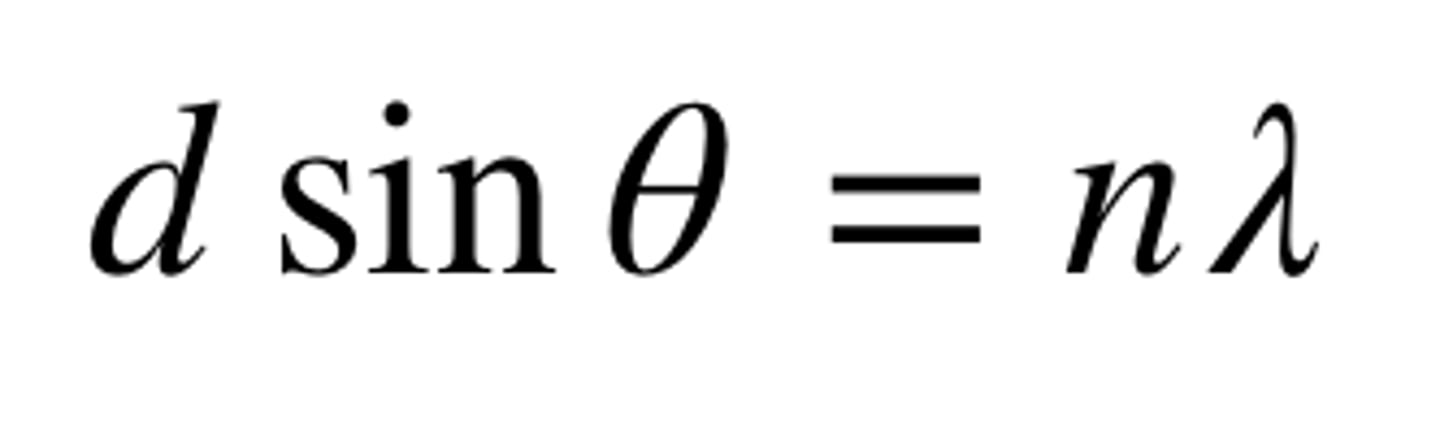
diffraction grating formula:
maxima location
primary maxima width
other maxima widths
location: d sin(θ)=nλ
primary width: Δsin(θ) = 2λ/W for grating width W
other widths: Δsin(θ) = λ/W
Rayleigh Criterion
is the condition for resolving λ and λ + δλ
λ / δλ = mN
derived from minimum overlapping with maximum: mλ + λD/W = m(λ+δλ)
Circular Aperture: radius of Airy disc and angular resolution
sin(θ) = 1.22λ/d = α where d is the aperture diameter and α is the angular resolution
Fresnel Diffraction:
when to use
major difference from Fraunhofer
what assumption are made to simplify the general integral
used when the source and screen are not at a large distance from the aperture.
unlike Fraunhoer, we consider only a special case with S, the origin, and P being on the same line (making the linear term in the phase vanish).
assumptions: K(θS,θP)≈const, s and r ≈constants (but s+r is not)
Fresnel Diffraction integral
ψ_P ∝∫∫h(x, y) exp[ik(x²+y²)/2R] dx dy
where 1/R = 1/a + 1/b (a,b) are the siatances before and after the apperture along SP.
1D Fresnel Diffraction integral with a separable aperture function using u
ψ_P ∝∫h(x) exp(iπu²/2)du with bounds u₁ and u₂
where u = x√(2/(λR) )
what are C(w), S(w) and the cornu spiral
∫exp(iπu²/2)du from 0 to w is C(w) + iS(w)
they can be evaluated using the cornu spiral, with C(∞) = S(∞) = 0.5, C(-∞) = S(-∞) = -0.5
the [C(x1)+iS(x1)]−[C(x2)+iS(x2)] chord is the ψ_P at point P (which determines the origin and hence the integration bounds).
Fresnel integral of a circular aperture
we can replace x^2 + y^2 with ρ^2 and dx dy with 2πρ dρ to show that the amplitude spirals inward slowly on the imaginary plane. The vector from the origin to the relevant s = ρ^2 gives ψ_P.
Fresnel half-period zones:
what are they
what improtant properties they have
formula or determining the number of half period zones
are a way of conceptually separating the aperture into concentric areas, each over which the contributed phase at P is π out of phase. This helps determine wether they all cancel out or not.
properties:
- the area of each zone is the same
- Odd numbered zones add to, and even numbered zones subtract from the overall amplitude at P. An even number of zones means zero intensity at P.
- an odd number will lead to a bright spot of 4Iu (Iu is the unobstructed intensity)
- For large apertures, the effect of 1/r and K(s) <1 is noticeable, and the zones become larger.
a² = NλR
Poisson's spot
appears on the axis behind a circular obstruction because the unobstructed outer Fresnel zones interfere constructively at the center.
Its brightness is approximately the same as the unobstructed case because the blocked inner zones would nearly cancel anyway, while the remaining outer zones sum to almost the same phasor (from F to A on the spiral), provided the obstruction is not too large.
nintensity on axis at focus of a fresel half period plate: formula and justification
I_p = 4N^2 I_u
ψu is the unobstrcted phase., which is ythe vector OF on the spiral diagram (o the origin, F is at the center when s=inf). hence one half circle of the spiral contributes a vector equal to the diameter in the phase diagram - 2ψu. If all the vectors pointing down are canceled, and we have N open zones, we get a final ψ_tot = 2Nψu . hence I_p = 4N^2 I_u
minima and foci along the axis of a fresnel half period plate: idea formula
when an open area of the plate allows throughan even number of zones, we get cancellation again: ψP = 0. when each open area of the zone plate admits an odd number of Fresnel zones, (one per each of the N open areas) ψP → 2Nψu and we get maxima. this is reduced by the decreasing K for the outer zones.
minima: R ′ = f /2m
maxima (subsidiary foci): R ′ = f /(2m+1)
ℜ(A)
Im(A)
identities
ℜ(A) = 1 2 (A + A ∗ )
Im(A) = 1 2 (A - A ∗ )
proof that we require ω₁ ≈ ω₂ to observe interference
Ψ = ℜ [ψ₁ exp(−iω1t) + ψ₂ exp(−iω2t) ]
I∝ Ψ² = ...
for Ψ₁=a₁exp(iϕ₁):
= 1/2
for (ω₁-ω₂)τ ≫ 1 , where τ is the averaging time of the detector, the third term averages to zero. So we need a very small ω₁-ω₂.
amplitude division: concept and typical ways to do
Amplitude division is the splitting of a wave into multiple parts by dividing its field amplitude, typically using partial reflection/transmission at interfaces such as beam splitters, semi-transparent mirrors, or diffraction gratings.
The Michelson Interferometer:
setup
how is a pattern observed
setup is like the michelson moorley experiment, with a beam splitter and two paths for the light, before recombination and detection.
The pattern can be observed by varying the angle, or more usually by moving the plate sinusoidally and measuring I(t) at a single point.
The Michelson Interferometer:
I(x) expression for monochromatic light.
= I₀(1 +ℜ[exp(ikx)])
derived from = 1/2
The Michelson Interferometer:
I(x) expression for broadband light
how is this useful for spectrometers?
I(x) = I₁ + ∫S(k) (1 +exp(ikx) )dk from −∞ to ∞
I₁ = ∫S(k) dk from −∞ to ∞ is the total intensity.
2S(k)dk is the intensity of light of wavenumber k to k+dk
NOTE: this is caused by summing intensities, not interference, since ω₁≠ω₂
use: S(k) = ∫[ I(x) - I₁ ]exp(-ikx) dx from −∞ to ∞
so s(k) = FT( I(x) - I₁ )
intensity pattern and Fringe visibility of two closely packed wavelength
I(x) = I₁[1+ cos(k₀x)cos(Δkx)]
Visibility = (I_max - I_min)/(I_max + I_min)
The high frequency cosine cos(k0x) represents the fringes (k0≫Δk) while the low frequency envelope cos(∆kx) modulates the amplitude of these fringes.
At the position of the first zero in the low-frequency envelope, the fringe contrast will be zero and this can be used to find ∆k.
phase difference introduced by a thin film
δ = 2n d k cos θ = 4πnd/λ cos θ were d is the thickness.
I(δ) : intensity introduced be focusing the light from a thin film
I(δ) = I₀( 1 - ℜ[ exp(iδ) ] )
since there is a phase difference of π, giving the - , at one of the boundaries, and another phase δ introduced by θ changing the path difference
![<p>I(δ) = I₀( 1 - ℜ[ exp(iδ) ] )</p><p>since there is a phase difference of π, giving the - , at one of the boundaries, and another phase δ introduced by θ changing the path difference</p>](https://knowt-user-attachments.s3.amazonaws.com/cfbd97b8-02cd-49cd-965b-5b29e56d2f7b.jpg)
total amplitude exiting an ethalon film + derivation.
A = T/( 1- R exp(iδ) )
derived by acknoledging the ligh aquires ampliture r^2 = R and phase exp(iδ) for each extra cycle. A = T(1 + R exp(iδ) + (R exp(iδ))^2 + (R exp(iδ))^3 .... ) = T/( 1- R exp(iδ) )

δ_(1/2) formula (the δ that reduces the intensity to half its value)
finesse
δ_(1/2) = (1-R) /√R
derived by squaring the amplitude to get the intensity, setting aside the onstant factor, recognizing that the deniminator 1 + [4R/(1 − R) 2 ] sin²(δ/2) will be doubled from minimum (=1) when [4R/(1 − R) 2 ] sin²(δ/2) =1 , and using small angle approximation for δ/2 .
F = 2π / ( 2δ_(1/2) ) = π√R / ( 1-R)
where the finess is defined as the ratio of separation of successive peaks in δ (equal to 2π) to their full-width at half maximum (2δ_(1/2))
chromatic resolving power and free spectral range of an etalon
resolving power: λ/∆λ = mF
free spectral range: (∆λ)_fsr = λ/m
he wavelength difference at which overlapping bwtween the signal from one spectrum of order m and another from order m+1 happens.