Fluoroscopy - Image Intensifiers (11/26/2024 & 12/3/2024)) (copy)
1/65
There's no tags or description
Looks like no tags are added yet.
Name | Mastery | Learn | Test | Matching | Spaced | Call with Kai |
|---|
No analytics yet
Send a link to your students to track their progress
66 Terms
Fluoroscopy is also referred to as ___
dynamic imaging
Early fluoro screens were composed of ___
zinc cadmium sulfide
(emits a yellow-green light)
What is “dark adapt”?
radiologist had to wear dark goggles for 20-30 minutes prior to start of exam (to adjust their eyes)
What are the parts of the eye and what purpose do they serve for vision?
iris: diaphragm
cones: daylight and central vision
rods: night and peripheral vision
What were some early fluoro modifications after biological hazards were recognized?
primary beam enclosed in lead
image transmitted to an optical viewer
no more “dark adapting”
When was the image intensifier introduced?
1948
What did the image intensifier do for early fluoroscopy?
converts x-rays to visible light with higher energy
brightened image
eliminated need for dark adaptation
use cone vision
improved visualization of detail and contrast
What is the most common tube/ii configuration?
under-table x-ray tube
tube and collimator are below tabletop
ii mounted above table
protective curtain and bucky slot (lead)
What is the typical mA range for fluoro?
0.5-5 mA (low mA, longer time)
What is the minimum SOD for stationary and mobile fluoro units?
stationary: 15”
mobile: 12”
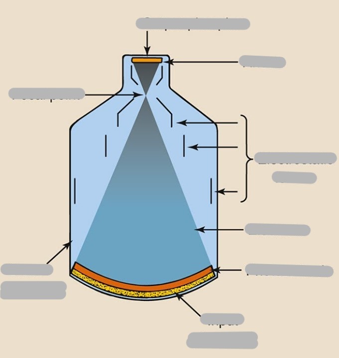
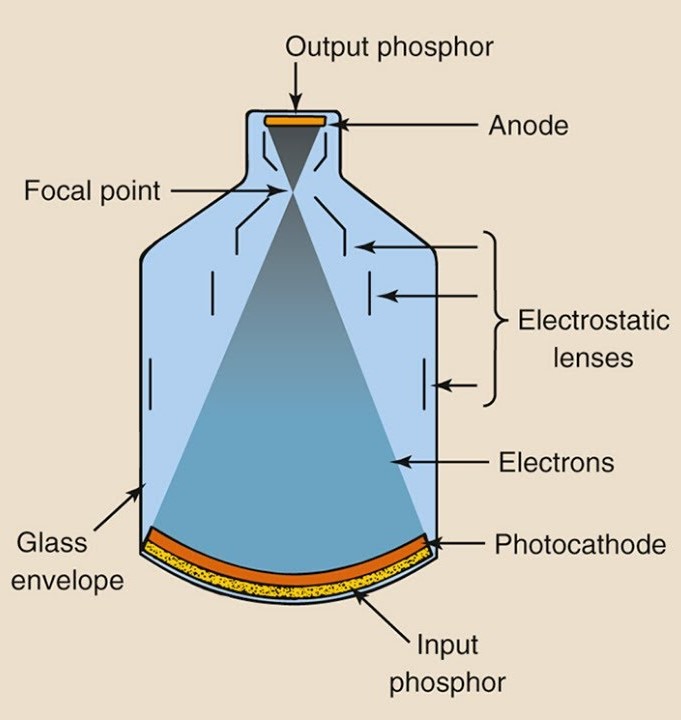
What are the 5 basic parts of the vacuum tube?
input phosphor/screen
photocathode
electrostatic lenses
accelerating anode
output phosphor/screen
Explain the input screen (as one of the 5 basic parts of the ii tube)
converts x-ray photons to visible light (yellow-green spectrum)
6-23” diameter convex screen
typically 6”, 9”, 12”, or 16”
glass, titanium, steel, or Al
screen coated with cesium iodide (CsI) crystals
0.1-0.2 mm layer
needle shaped (columnar crystals)
tightly packed
Explain the photocathode (as one of the 5 basic parts of the ii tube)
absorbs light photons and emits electrons (process of photoemission)
photoemissive materials - cesium antimony compounds
thin protective coating between input screen and photocathode (prevents chemical reaction between layers)
Explain the electrostatic focusing lens (as one of the 5 basic parts of the ii tube)
series of metal bands or rings with increasing positive charge
focuses electrons toward anode ring
become narrower to focus electrons
electrons concentrated onto output screen (smaller)
Explain the accelerating anode (as one of the 5 basic parts of the ii tube)
located in front of output screen
positive charge attracts electrons and accelerates them toward output screen
potential difference = at least 25 kV
increased energy from anode to output screen = flux gain
electrons pass through hole in center
strike output screen
Explain the output screen (as one of the 5 basic parts of the ii tube)
converts electrons to light photons (visible light)
made of zinc cadmium sulfide or cesium iodide
electrons strike screen and emit green light
diameter = 1”
light then passes to CCD or camera tube
thin aluminum coating prevents light backflow
newer units have fiber-optic disc in place of screen
What are multi-field ii?
tubes with more than one size input screen
dual field: 9/6 inch
tri field: 10/7/5 inch
have mag mode
number refers to diameter of input screen of ii
What is the focal point?
the point where electrons cross
(moves based on voltage applied to focusing lens)
image is magnified at output screen
The ___ the voltage applied, the closer the focal point moves to input screen
higher
Explain the effect of magnification mode
optical system can only see the central part of image
central, straighter rays strike output (reduces FOV, improves resolution)
image is less minified
brightness is decreased
mA is automatically increased to compensate for decreased brightness (due to minification screen)
mag mode:
___ FOV
___ resolution
___ brightness
___ mA
reduces FOV
improves resolution
decreases brightness
increases mA
Magnification intensifiers can mag ___
between 1.5-4x
Magnified image ___ patient dose
increases
(more x-rays required to form image; ABC boosts technical factors to create more signal)
smaller field = ___ resolution = ___ dose
smaller field = improved resolution = higher dose
magnification equation
magnification = (input screen diameter)/(input screen diameter in mag mode)
What are some common brightness control systems?
ABC
ADC
ABS
What does ABC stand for?
Automatic Brightness Control
What does ADC stand for?
Automatic Dose Control
What does ABS stand for?
Automatic Brightness Stabilization
What does AGC stand for?
Automatic Gain Control
What does AGC do?
adjusts current flowing to display monitor
DOES NOT adjust kVp and mA
What does ABC do?
automatically maintains fluoro image density and contrast (mA/kV)
rad selects brightness level desired
maintained during exam
Explain image lag in ii systems
ii systems have slow response time to adjusting to changes in tissue density
Brightness gain
the ability of an ii to increase image illumination
Total brightness gain
measurement of the increase in image intensity achieved by the ii
Total brightness gain is determined by ___
minification gain and flux gain
Minification gain
increase in image brightness or intensity
occurs as electrons are compressed into smaller area
same number of light photons are concentrated on a smaller screen, creating a bright image
Minification gain equation
minification gain = (di/do)2
di = diameter of input phosphor
do = diameter of output phosphor
Flux gain
anode accelerates electron toward output screen
acceleration increases kinetic energy
increased light intensity at output phosphor
electrons arrive at output screen with increased energy
50-75 times more
Flux gain equation
flux gain = (number of output light photons)/(number of input x-ray photons)
Brightness gain equation
brightness gain = minification gain x flux gain
Brightness gain may deteriorate as much as ___
10% per year (due to aging of screens)
Conversion factor
ICRU rates brightness gain by conversion factor
ratio light intensity at the output phosphor / radiation intensity at the input phosphor
measures how efficiently ii converts x-ray energy to light energy
What are 3 types of output screen attachments?
TV/video tubes, CCDs, CMOs
Explain TV/video tubes (old output screen technology)
coupling device sends signal from output screen to viewing monitor
beam splitter used to send image data to spot film and cine camera
image must be converted to electrons to be sent to viewing devices
vidicon or plumbicon tube converts light from output phosphor to electrical signal
electrical signal sent to television monitor for viewing
Explain charge coupled devices (CCDs) as a type of output screen attachment
coupled to output phosphor by optic cables
small, flat plate
light strikes CCD
CCD releases electrons proportional to incident light
stores image in latent form
emits signal in raster pattern
IR is divided into squares (DELs)
signal is collected, stored, and released
What are some benefits of CCDs?
faster discharge time (no image lag)
operates at much lower voltages (extends tube life)
high contrast images
high resolution
high SNR
high DQE (high sensitivity, decreased technique, decreased exposure)
Explain complimentary metal oxide semiconductor (CMO) as a type of output screen attachment
coupled to output phosphor by optic cables
small, flat plate
converts light form output screen to electronic signal
lower image quality
each DEL contains readout components
Explain the difference in DEL readout in CCD and CMO
CCD DELs read out in groups/lines
CMO DELs read out individually
CCD has ___, but CMO has ___
CCD has higher image quality, but CMO has economic advantages
What is the most restrictive component of any fluoro system?
viewing monitors
List 4 components of image quality
contrast
resolution
distortion
quantum mottle
Explain contrast as 1 of the 4 components of image quality
degradation between input and output screen
affected by penumbral light scatter
background fog
incident photons striking output screen
deteriorates approximately 10% per year the fluoro system is in use
Explain resolution as 1 of the 4 components of image quality
greatest limitation comes from video monitor
detail determined by geometric factors
OID
phosphor size and thickness
want thin layers and small crystals
input and output screen diameter
input is much bigger, gets squished down to output size
screen resolution
Explain distortion as 1 of the 4 components of image quality (know the 3 types)
pincushion - distortion of lines
caused by curvature of input screen and flatness of output screen
vignetting - brightness varies from center of image to edge
potentially a consequence of pincushion
veiling glare - light scatter from output screen degrades contrast
Explain quantum mottle as 1 of the 4 components of image quality
blotchy or grainy image caused by insufficient radiation
factors contributing to quantum mottle:
video noise
radiation output
beam attenuation by subject
conversion efficiency of ii
minification gain
flux gain
brightness gain
solution = increase mA
Explain flat panel digital fluoro
flat panel replaces ii - TFTs
added CsI scintillation
increased SNR
pixel binning - combines up to 4 pixels at once
results in lower noise
resolution - not as high as radiography
clinical value outweighed by patient exposure concerns
less patient dose
improved contrast
What are some features of dynamic flat panel fluoro detectors?
zoom feature (can zoom without MAG = no dose increase)
LED “refreshes” detector between frames
prevents ghosting
last image hold
maintains last image real time
less distortion
post processing algorithms
window width and level
edge enhancement
digital subtraction
What are some advantages of digital fluoro?
reduces patient dose by as much as 50%
operates at 2-20 mA
pulsed fluoro
frame grabbing
last image hold
filtering
high DQE and SNR
patient dose is displayed
durable (doesn’t degrade with age)
reduced artifacts
less veiling glare and pincushion distortion
less geometric distortion
Explain over-table x-ray tube
configuration results in increased exposure to personnel
may be equipped for remote control operation
Explain fixed c-arms
may be mounted from ceiling or floor
applications include:
cardiac
peripheral and neuro angiography
interventional procedures
Explain mobile c-arms
c-shaped arm with x-ray tube mounted on one end an ii on the other
small, 10-15cm diameter ii
connected to viewing monitor
used in ED, ICU, GI, pain, OR, etc.
Explain mini c-arm
compact system with a small image intensifier
designed for imaging extremities
Explain Bi-plane equipment
consists of:
1 floor mounted c-arm
1 ceiling mounted u-arm
each is capable of individual or simultaneous motion and operation
Explain radiation protection
tech is gatekeeper
time
timer: 5 minute alarm
distance
SSD not more than 15” with fixed unit, 12” for mobile
shielding
aprons and gloves 0.5 mm Pb
0.25 mm lead drape and lead shield over bucky slot
collimate to anatomy when in mag mode
stand behind radiologist
exposure at tabletop not to exceed 10R/min