[ AETN1112 ] Boolean Algebra and Logic Gates
1/19
There's no tags or description
Looks like no tags are added yet.
Name | Mastery | Learn | Test | Matching | Spaced | Call with Kai |
|---|
No analytics yet
Send a link to your students to track their progress
20 Terms
Logic 0
This can be: false, off, low, no, and open switch.
Logic 1
This can be: true, on, high, yes, and closed switch.
Truth Table
This describes the relationship between the input and
output of a logic circuit
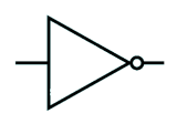
NOT
Also called as inverter. The simplest digital logic gate with one input and one output that produces the logical opposite (complement) of its input
X = A bar
The Boolean expression for NOT gate
Bubble Symbol
This means inversion. That is, if we have a “1” on one side of the bubble, then we have a “0” on the other side.
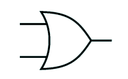
OR
A fundamental digital circuit that outputs a high signal (1 or "true") if any of its inputs are high, and a low signal (0 or "false") only when all inputs are low, performing a logical disjunction or Boolean addition (A + B = Q)
X = A + B
The Boolean expression for OR gate
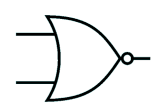
NOR
A digital logic gate that outputs a high signal (1) only when all of its inputs are low (0); otherwise, the output is low (0), essentially inverting the result of an OR gate.
X = A + B bar
The Boolean expression for NOR gate
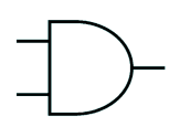
AND
A fundamental digital logic gate that outputs a high signal (1) only when all of its inputs are high (1); if any input is low (0), the output is low (0)
X = AB
The Boolean expression for AND gate.
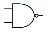
NAND
A fundamental digital logic gate that produces a LOW (0) output only when all its inputs are HIGH (1); otherwise, the output is HIGH (1).
X = AB bar
The Boolean expression for NAND
OR
NOT
AND
NOR
NAND
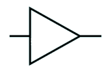
Buffer