laser scanning confocal microscopy
1/20
There's no tags or description
Looks like no tags are added yet.
Name | Mastery | Learn | Test | Matching | Spaced | Call with Kai |
|---|
No analytics yet
Send a link to your students to track their progress
21 Terms
introduction
Confocal microscopy offers several advantages over conventional wide-field optical microscopy, including;
The ability to control depth of field.
Elimination or reduction of background information away from the focal plan.
Collection of serial optical sections from thick specimens.
The basic concept of confocal microscopy was originally developed by Marvin Minsky in the mid-1950s (patented in 1961) when he was a postdoctoral student at Harvard University.

Laser scanning confocal fluorescence microscopy (LSCM) has become an essential tool in biology and the biomedical sciences.
The application of synthetic and naturally occurring fluorophores has made it possible to identify cells and sub-microscopic cellular components.
The confocal microscope is often capable of revealing the presence of a single molecule.
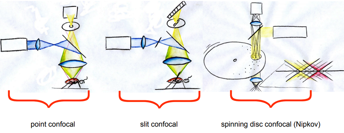
MORE THAN ONE TYPE OF CONFOCAL MICROSCOPY
Best resolution and out-of-focus suppression as well as highest multispectral flexibility is achieved only by the classical single point confocal system !
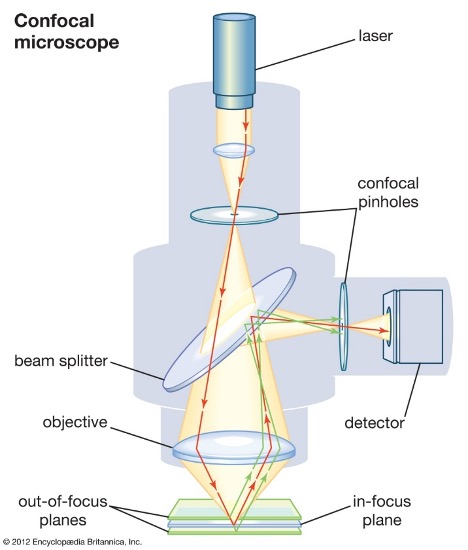
The microscope
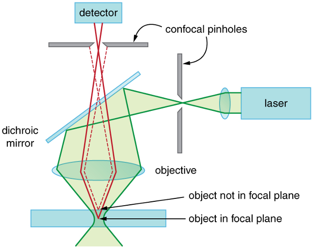
Coherent light emitted by the laser system (excitation source) passes through a pinhole aperture.
The laser is scanned across the specimen in a defined focal plane.
Secondary fluorescence emitted from points on the specimen pass back through the dichromatic mirror and are focused as a confocal point at the detector pinhole aperture.
Filters can be added in-front of both laser and detectors.

Fluorescence emission that occurs at points above and below the objective focal plane is not confocal with the pinhole
not detected by the photomultiplier
does not contribute to the image.
Refocusing the objective shifts the excitation and emission points on a specimen to a new plane.
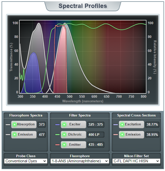
Selecting Filters and Dichroic Mirrors
Modern fluorescence microscope instrumentation employs a combination of interference filters and a dichromatic beam splitter to satisfy the excitation and emission requirements of the fluorescent probe(s) used to label the specimen.
By carefully matching excitation and emission filter properties with the function of the dichromatic beamsplitter, labelled specimen features are imaged on a dark background with maximum sensitivity.
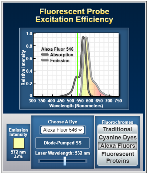
Fluorescent Probe Excitation Efficiency
In confocal microscopy, the wavelength range of the absorption and emission bands, the molar extinction coefficient for absorption and the quantum yield for fluorescence emission should be considered.
At laser excitation levels that do not saturate the fluorophore, fluorescence intensity is directly proportional to the product of the extinction coefficient and the quantum yield.
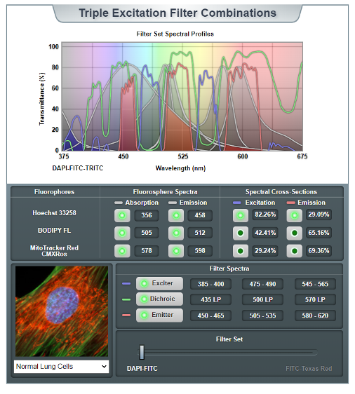
Triple Excitation Filter System
Multi-labelled systems must be capable of selectively isolating fluorescence emission through narrow bands of the blue, green, yellow, orange, and red spectral regions.
Spectral separation is required to prevent fluorescence energy transfer.
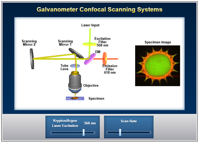
Galvanometer confocal scanning systems o
In order to generate a digital image from an extended specimen in laser scanning confocal microscopy, the focused beam is scanned laterally (in the x-y plane) across the specimen surface in a rectangular raster pattern.
Modern instruments utilize a scanning mechanism based on two high-speed vibrating mirrors driven by galvanometer motors to produce the scanning pattern.
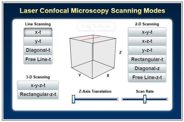
Laser Confocal Microscopy Scanning Modes
The wide range of laser scanning modes available in modern confocal microscopy enable investigators to fine-tune acquisition strategies in order to optimize data collection for three-dimensional imaging, time-lapse analysis, and a host of other specialized applications.
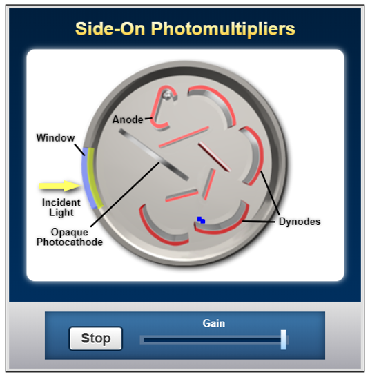
Detector: Side-On Photomultipliers
The high performance ratings and low cost, side-on photomultipliers are the most widely used tubes for general photometric applications, such as spectrophotometry, fluorimetry, and confocal microscopy.
The Pinhole
In simple terms the pinhole is equivalent to the iris diaphragm found on compound microscopes.
It controls the amount of light entering or leaving an optical component.
The detection pinhole removes all emission not originating from the focal plane – ’spatial filter’.
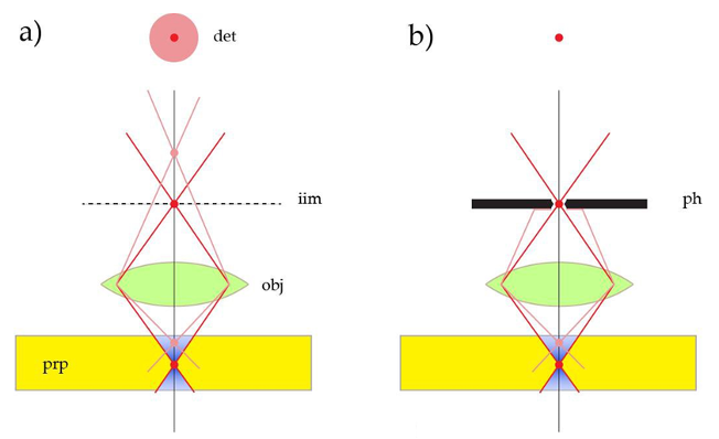
As the device cuts out sections from the sample by optical means, it is also called the ‘optical knife’.
The optical knife. a) a compound microscope generates an intermediate image (iim) by an objective lens (obj), containing both focal (red) and extrafocal (pink) signal emanated by the sample (prp). When imaging a single spot, the detector (det) will record both a spot-shaped feature from the focal plane and extended blurry discs from other regions. b) by introducing a pinhole aperture (ph) in the intermediate image plane, nearly all extrafocal signal is cut off and solely the emission from the focal plane can reach the detector. The spatial filter generates an optical section.
The pinhole
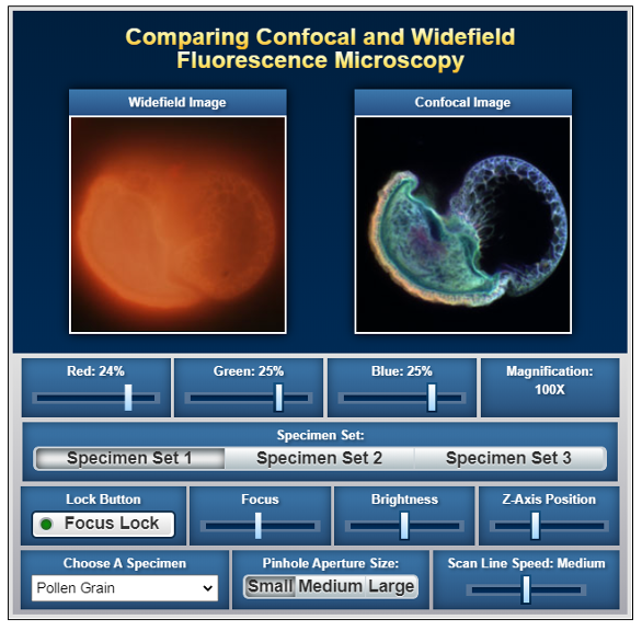
For general confocal imaging, the recommendation is to just transmit the inner part of the diffraction limited feature by the pinhole – The Airy Disk.
The size of Airy disc in the intermediate image depends on the wavelength (colour), on the NA, the magnification of the objective lens and the magnification of internal optics of the microscope.
A variable pinhole allows the increase the optical sectioning sharpness by lessening the diameter or to reduce optical sectioning performance by increasing the diameter.
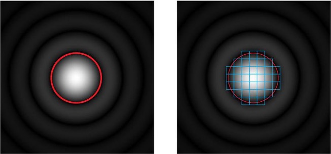
Pinhole diameter and diffraction pattern. On the left: red circle indicates a circular pinhole adjusted to 1 AU. This pinhole will cut out the inner disk of the diffraction pattern and generate an optical section of the dimension dz. AU = “Airy Unit”. On the right: for image rescanning microscopy, a series of subsets of the diffraction pattern is recorded. These images are combined and show increased lateral resolution (compared to widefield). The optical sectioning performance will still assume the equivalent of the rescanned area, i.e. is equivalent to a pinhole set to a size indicated by the red ring.
The Pinhole
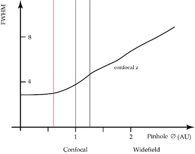
Axial response to pinhole diameter. A practical setting for confocal microscopy is a diameter of 1 AU (grey vertical). When increasing the diameter, the detector will pick up extrafocal signal, the z-sectioning performance is deteriorated, although the intensity might increase. For pinhole diameters below 1 AU the sectioning performance will still increase, but assume a finite diffraction limited value at diameter zero.
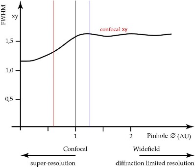
Lateral response to pinhole diameter. The lateral resolution at 1 AU is constant for increasing diameters and corresponds to ordinary widefield microscopy resolution (diffraction limited resolution). If the pinhole diameter is below 1 AU, the lateral resolution is improved. The maximum increase in resolution is some 30% at pinhole diameter zero. Already at pinhole diameter 0,6 AU about 60% of the possible resolution increase is exploited (red vertical).
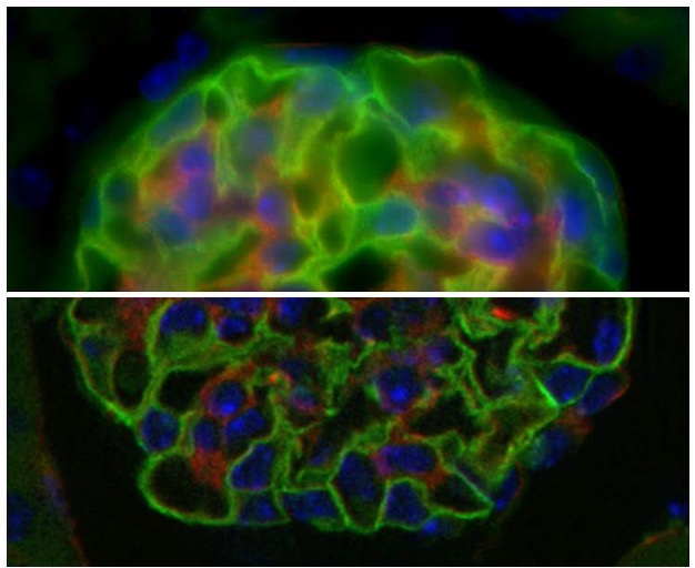
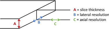
Resolution
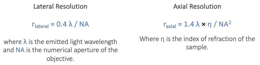
wide-field vs confocal
Imaging
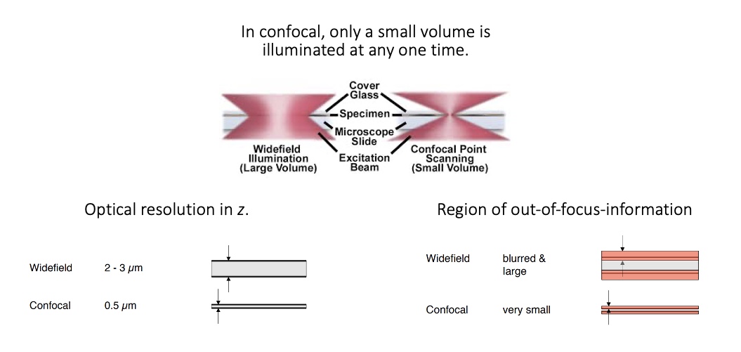
In a conventional widefield optical epi-fluorescence microscope, secondary fluorescence emitted by the specimen often occurs through the excited volume and obscures resolution of features that lie in the objective focal plane.
Confocal microscopyis able toexclude secondary fluorescence in areas removed from the focal plane from resulting images.
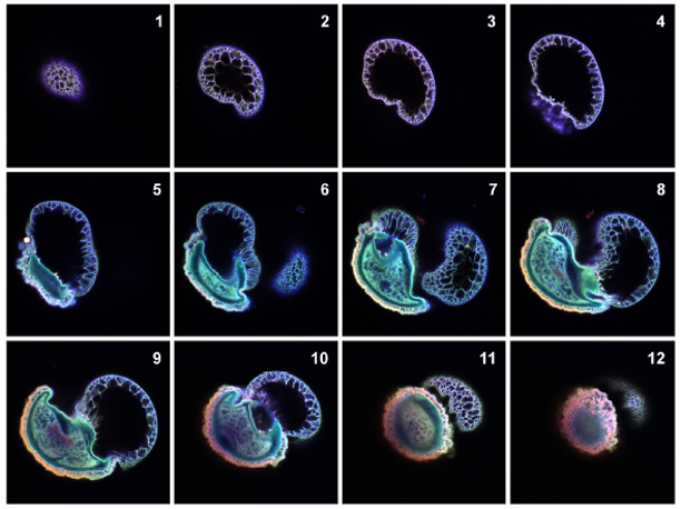
Optical sections
Serially produce thin (0.5 to 1.5 μm) optical sections
Thickness ranging up to 50 μm (or more).
Image series is collected by coordinating incremental changes in the microscope fine focus mechanism.
Optical sections
Image formation is restricted to a well-defined plane.
Confocal optical sectioning technique enables the examination of both living and fixed specimens.
Software packages - optical sections collected to produce 3D images.
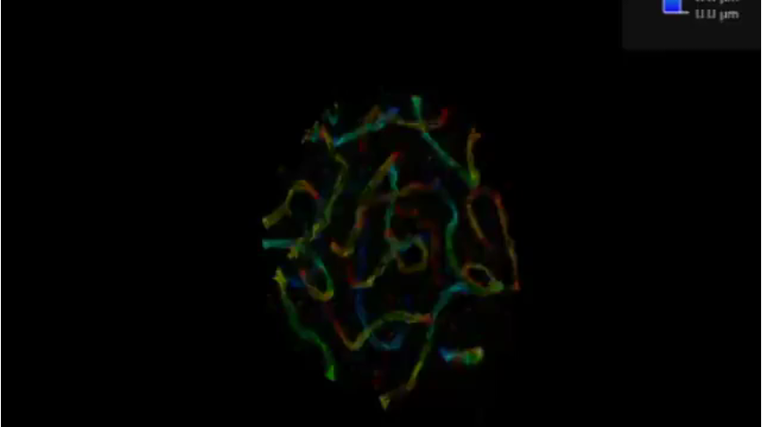
3D Imaging
Leica SR GSD 3D:
3D reconstruction of the synaptonemal complex protein 3 (SYCP3) stained with Alexa 647.
Medium: 50 mM MEA in PBS.
Five image stacks each 800 nm in thickness were merged.