1725 Distortion
1/43
There's no tags or description
Looks like no tags are added yet.
Name | Mastery | Learn | Test | Matching | Spaced | Call with Kai |
|---|
No analytics yet
Send a link to your students to track their progress
44 Terms
Distortion Definition
A misrepresentation of the size and or shape of the anatomical part being imaged
Distortion can be classified as either
Size
Shape
Factors Affecting Size Distortion
OID
SID
Factors Affecting Shape Distortion
Alignment
Central Ray
Part
IR
Angulation
Direction
Degree
Size Distortion (Magnification)
An increase in the image size of an object compared with its true or actual size
Radiographic images of objects are always magnified in terms of the true object size
SID and OID are important factors
Magnification
Reducing magnification - Reduces size distortion, therefore increasing spatial resolution
The objective in radiography is to minimize magnification as much as possible
Magnification radiography is the exception to this rule
Magnification Radiography
Used in Interventional Radiology and Mammography
Enhances the visualization of small structures
Conventional radiography strives to minimize magnification
Magnification Radiography deliberately increased OID to cause magnification
How to calculate the Magnification Factor
MF = Image Size/Object Size
How is magnification assessed
By calculation of the magnification factor = degree of magnification
How to calculate size distortion
M = SID/SOD
What does the magnification factor permit calculation of
The actual size of an object that is projected as an image
Formula for actual size
O = I/M
O = Object Size
I = Image Size
M = Magnification Factor
Large SID
Use as large a source to image receptor distance as possible to reduce magnification
Small OID
Place the object as close to the image receptor as possible (To reduce magnification)
Source to Image Receptor
A major effect on magnification
The greater the SID, the smaller the magnification
This is because as SID increases, the percentage of total distance that makes up OID decreases
Magnification size distortion is minimized by increasing SID
Object to image receptor
Very critical when discussing magnification and resolution
Short OID, Large SOD - Low Entrance skin exposure
Large OID, Small SOD, - High entrance skin exposure
Shape Distortion
Unequal magnification of different portions of the same object
Shape Distortion depends on
Object thickness
Object position
Object shape
Displaces the projected image of an object from its actual position and can be describes as either:
Elongation
Foreshortening
Elongation
Projects the object so it appears to be longer than it really is
Foreshortening
Projects the object so it appears shorter than it really is
Any misalignment of the CR among which 3 factors alters the shape of the part recorded in the image
Tube
Part
Or Image receptor
Factors Affecting Shape Distortion
Alignment
Central Ray
Anatomical Part
Image Receptor
Angulation
Degree
Direction
Alignment
Shape distortion can be caused or avoided by alignment of the central ray with the anatomical part and central part
Proper position is achieved when the central ray is at right angles to the anatomical part and the image receptor
This means the part and image receptor must be parallel
Creative Alignment
When the position of the body part or object within body do not permit alignment, this is utilized
Examples:
25 degree cephalic angulation of the pelvis to demonstrate sigmoid colon
10 degree caudal angulation of the coccyx
These angles help minimize distortion
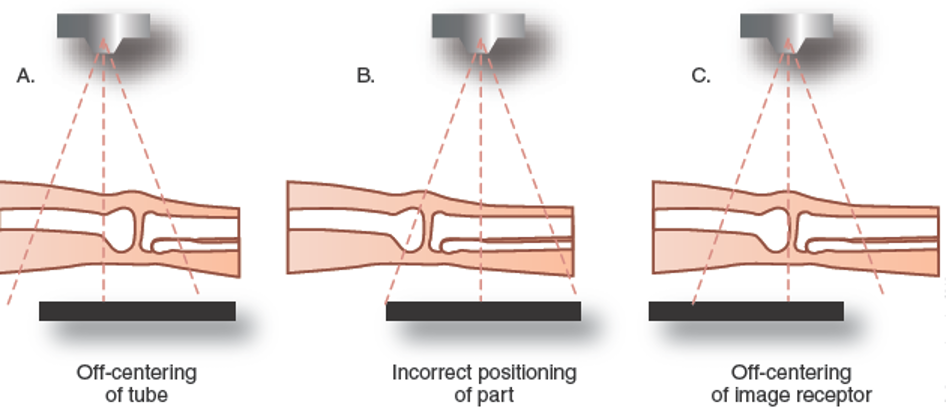
Incorrect Centering
Alignment adjustments involve bringing the tube central ray, the part, and image receptor back to their correct relationship
Central Ray
Ideally, the central ray is intended to be projected perpendicular to both the anatomical part and the image receptor
Whenever the central ray is not perpendicular, some degree of distortion will occur
This occurs in every image because the central ray is not truly perpendicular
Any structure which is not positioned at the central ray
Will be distorted because of the divergence of the beam
Farthest from the central ray
Greater distortion
The long axis of the anatomical part is intended to be positioned
Perpendicular to the central ray and parallel to the image receptor
The image receptor is intended to be positioned
Perpendicular to the to the central ray and parallel to the anatomical part
If IR is not parallel to object or if central ray is not centered to part, serious distortion can take place
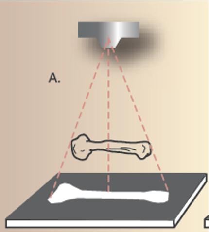
Normal Relationship between part and IR
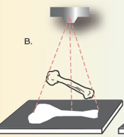
Foreshortening and magnification due to part alignment
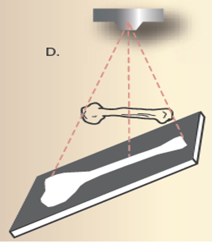
Elongation and magnification due to changes in part/IR and Central Ray/IR alignment
What does angulation refer to
The direction and the degree the tube is moved from its normal position perpendicular to the image receptor
What is angulation used to avoid
Superimposition of parts
Angulation in tube results in
Some form of distortion
Angulation does what to SID
Increases SID which will decrease exposure to IR
Most common tube angle
Longitudinal which are often termed cephalic or caudal
Angled Transverly
“Roll”
What is direction of tube angle dependent on
Patient position Ex: 25 degree cephalic AP projection is identical to 25 degree caudal PA projection
Evaluating Shape Distortion
Shape distortion is more subjective than size
Relies on radiographer’s knowledge of normal anatomy and the normal projected images for each position
What is size distortion generally
Magnification
All magnification involves
A degree of loss of resolution