P4/P5 - Electricity
1/124
There's no tags or description
Looks like no tags are added yet.
Name | Mastery | Learn | Test | Matching | Spaced |
|---|
No study sessions yet.
125 Terms

Positive and negative terminals

Single cell
provides cell with source of potential difference

Battery of cells

Open switch
Turns circuit on

Closed switch
Turns circuit off

Lamp
Emits light when electric current passes through it

Resistor (Fixed)
limits the flow of current. A fixed resistor has a resistance it cannot change

Resistor (Variable)
resistor with a slider that can be used to change its resistance. These are often used in dimmer switches and volume controls

A resistor that changes its resistance with temperature. The resistance of a thermistor depends on its temperature as its temperature increases, its resistance decreases and vice versa

resistance of an LDR depends on the light intensity as the light intensity increases, its resistance decreases and vice versa

A diode allows current to flow in one direction only. They are used to convert AC to DC current
Rectifier
A rectifier is a component that turns an alternating current into a direct current
Examples of recitifer
Diode
How do diodes act as recitifers
The diode blocks the alternating current when it changes direction
How does a rectifier work
The AC current goes into rectifier → Diode blocks the AC current and changes it → DC current is an output of the rectifier

This is equivalent to a diode and emits light when a current passes through it. These are used for aviation lighting and displays

breaks the circuit if a fault in an appliance causes too much current to flow. This protects the wiring and the appliance if something goes wrong

Used to measure the current in a circuit. Connected in series with other components

Used to measure the potential difference. Connected in parallel with other components
Direction of current flow
Positive → Negative terminal of the power supply
Components in an electrical circuit diagram
Energy source → Source of potential difference such as : Power supply/Cell/Battery
Closed path or complete circuit → Electrons need to flow in a complete loop for a current to flow
Electrical components → They act as sensors to respond to the environment such as: LDR/Thermistor/Voltmeter x Ammeter/LED/Lamp
Potential difference
energy transferred per unit charge flowing from one point to another
Sources of potential difference
Cell
Batteries
Electrical generators
Formula of potential difference (V)
V = E or W (J)/Q (C)
What measures potential difference
Voltmeter in parallel
Current
Flow of electric charge
Rate of flow of electric charge
How much charge passes through a point per second
Unit for current (I)
Amperes (A)
Unit of charge (Q)
Coulombs (C)
1C
1A s (1 ampere each second)
Charge flow formula
Q = I (A) x t (s)
Direction of electron flow
To the positive terminal
Conventional current
the flow of positive charge from the positive terminal of a cell to the negative terminal. Opposite to electron flow
Measuring current
Ammeter in series
Current in series
Current value is same as the circuit is in a closed loop
Resistance
Opposition to current
Higher resistance
Lower current
Resistance in conductors
Low
Resistance in insulators
High
Unit for resistance (R)
Ohms (Ω)
Ways to increase resistance
Adding resistors
Formula for potential difference using resistance and current
V= I(A) x R(Ω)
Ohms law
current through a conductor is directly proportional to the potential difference across it
Ohmic conductors
Electrical conductors obeying ohm’s law
Examples of ohmic conductors
Fixed resistors
Wires
Heating elements
Relationship between current and potential difference
If they are directly proportional, resistance remains constant
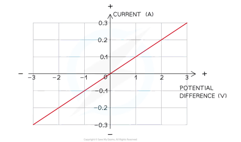
I-V graph of an ohmic conductor
Reversing potential difference won’t have an effect on shape of line
I -V are directly proportional
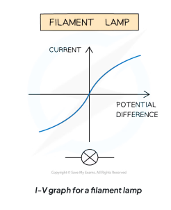
I-V graph of filament lamp
Non ohmic conductor as I-V are not directly proportional
Resistance of filament lamp increases as temp increases
As current increases, temp increases increasing resistance as high temp causes atoms in metal lattice of filament vibrates more.
Resistance is created as it is difficult for free electrons to pass through
Resistance increases as graph curves
Why resistance increases as temperature increases
Higher temperature makes atoms in the materials vibrate really quick which collide with electrons flowing through therefore slowing down their flow which decreases current
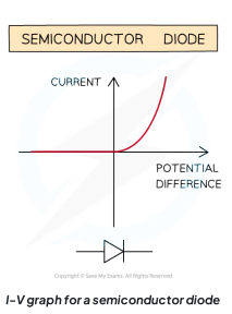
I-V graph in a semiconductor diode
Diode is a non ohmic conductor letting current flow in one direction only → Forward bias
In reverse direction, diode has very high resistance so no current flows → Reverse bias
Forward bias in graph → sharp increase in potential difference in right side of graph
Reverse bias in graph (When diode is switched around) → shown by a zero reading of current or potential difference on left side of graph
Thermistor
non ohmic conductor and temperature dependent resistor
Low temperature in a thermistor
High resistance as electrons will move slower
High temperature in a thermistor
Low resistance as more KE given to the electrons to move more freely and faster
Uses of thermistors
Thermostats → It regulates temperature
Ovens
Fire alarms
Refrigerators
Boilers
Digital thermometers
These are commonly used to regulate and monitor temperature in environments
LDR
Non ohmic conductor in which the resistance changes depending on its light intensity. LDR’s regulate amount of light intensity on it or activates a device when the light intensity reaches above or below a certain point
High light intensity of an LDR
Low resistance
Low light intensity of an LDR
High resistance
Uses of LDR’S
Lights that switch on when it gets dark (lights, streetlights)'
Alarm clocks
Burglar alarm circuits
Light intensity meters
Security lights
Street lights:
Daytime has high light intensity → LDR keeps light turned off
Nigh has low light intensity → LDR switches light on
Advantages of LDR
these circuits are automatic therefore not needing any human time and intervention to function correctly everyday
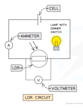
Investigating resistance in LDR circuit
Lamp turned off in dark room
Record reading on voltmeter and ammeter
Slowly increase light intensity of lamp using dimmer switch
Record reading on voltmeter and ammeter for each increase in light intensity
Calculate resistance using R=V/I
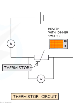
Investigating resistance in thermistor circuit
Heater turned off
Record reading on voltmeter and ammeter
Slowly increase heat of heater using dimmer switch
Record reading on voltmeter and ammeter for each increase in temperature of heater
Calculate resistance using R=V/I
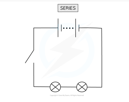
Series circuits
Circuit consisting of a string of two or more components, connected end to end
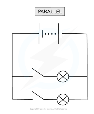
Parallel circuits
Circuit consisting of two or more components attached along separate branches of the circuit
Current/PD in series circuits
Current → Same at all points (I= I₁ = I₂)
PD → Shared between the components (If given potential difference, halve the PD)
Current/PD in series circuits
Current → Splits at junction with some going one way or the other
PD → Same at all points
Resistance in series circuits
Total resistance is sum of resistance in each component
Two resistors in series will have larger overall resistance than just one because charge has to push through multiple components when flowing around circuit
The more components that charge has to travel through, higher number collisions that occur
Resistance in parallel circuits
total resistance decreases and is less than the resistance of any of the individual components
two resistors in parallel will have smaller overall resistance than just one as charge has more pathways to take so only some charge will flow through each path
The more pathways, the lesser resistance
Voltage in series formula
V(in) = V₁ + V₂ ….
Voltage in parallel formula
V(in) = V₁ = V₂ ….
Current in series formula
I(in) = I₁ = I₂ …
Current in parallel formula
I(in) = I₁ + I₂ ….
Resistance in parallel formula
1/R(total) = 1/R₁ + 1/R₂ ….
Resistance in series formula
R(Total) = R₁ + R₂ …..
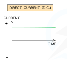
Direct current
Current that is steady, constantly flowing in one same direction in a circuit from positive to negative
Sources producing DC
Electric cells and electric batteries
Potential difference in DC circuits
One direction only
DC power supply
Has fixed positive terminal and fixed negative terminal
Advantages of series circuits
Cells connected in series give a greater resultant voltage than individual cells.
Voltage increases if the number of cells increases.
Series circuits do not overheat easily.
Disadvantages of series circuits
If one of component breaks, then all of others will stop working
Components can’t be controlled separately
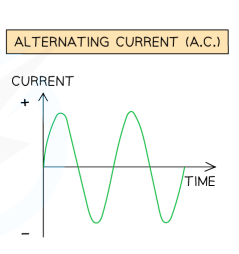
Alternating current
current that continuously changes its direction, going back and forth around a circuit
How many terminals in AC circuit
2 identical terminals
Potential difference in AC
Varies and represented as a sine curve
Frequency of AC
number of times the current changes direction back and forth each second
Mains electricity of UK
Frequency → 50Hz
PD → 230V
Mains electricity
electricity generated by power stations and transported around the country through the National Grid. It is AC current
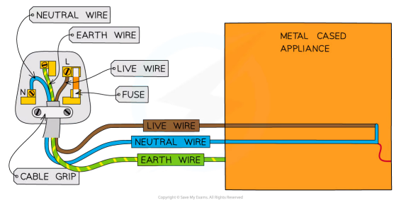
Parts of a three core cable
Neutral wire
Live wire
Earth wire
Fuse
Cable grip
Insulation colour coding for the three wires
Neutral → Blue
Live → Brown
Earth → Yellow/Green
Live wire
Carries alternating potential difference from mains supply to circuit
Most dangerous wire
If it touches appliance without earth wire, it causes electrocution
Neutral wire
Forms opposite end of circuit to live wire to complete the circuit
Lower voltage hence less dangerous than live wire
Earth wire
Acts as safety wire to stop appliance from being live
This prevents electric shocks if appliance malfunctions or if live wire touches casing of plug
It carries current to the ground if there is a fault by providing low resistance path
Power
The rate of energy transfer or the amount of energy transferred per second
Power formula (P) (with PD/Current)
P(W) = V(V) x I(A)
Power formula (P) (with Current/Resistance)
P(W) = I² (A) x R (Ω)
Power formula (P) (With Resistance/Voltage)
P(W) = V² (V)/R (Ω)
Amount of energy transferred to and from appliance depends on
How long appliance is switched on for
Power of appliance
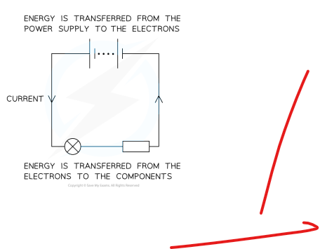
Energy transfers in a circuit
Power source → Energy released → Passed to Electrons → Electrons pass energy to components
Energy transfer from AC to appliances
KE → Electrical energy of motor
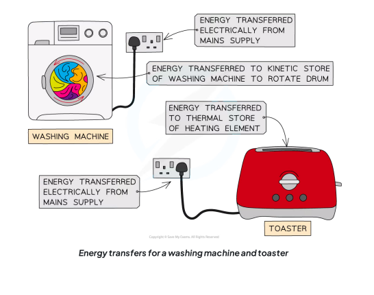
Uses of motors
Vacuum cleaners
Washing machines
Refrigerators
Energy formula with Power and time
E (J) = P(W) x T(s) or E = I(A) x V(v) x T
Energy formula with charge and Pd
E = Q (C) x V